Table of Contents
Advertisement
Quick Links
Advertisement
Chapters
Table of Contents

Related Manuals for IEI Technology PPC-5152-D525-E


Summary of Contents for IEI Technology PPC-5152-D525-E
- Page 1 PPC-5152-D525-E Panel PC PPC-5152-D525-E Panel PC MODEL: PPC-5152-D525-E 15” Panel PC with Touchscreen, Intel® Atom™ CPU, USB 3.0, Dual Gigabit LAN, RS-232/422/485, IP 64 Protection, RoHS Compliant User Manual Page 1 Rev. 1.10 – October 14, 2014...
- Page 2 PPC-5152-D525-E Panel PC Revision Date Version Changes October 14, 2014 1.10 Initial release Page 2...
- Page 3 PPC-5152-D525-E Panel PC Copyright COPYRIGHT NOTICE The information in this document is subject to change without prior notice in order to improve reliability, design and function and does not represent a commitment on the part of the manufacturer. In no event will the manufacturer be liable for direct, indirect, special, incidental, or consequential damages arising out of the use or inability to use the product or documentation, even if advised of the possibility of such damages.
- Page 4 PPC-5152-D525-E Panel PC WARNING This device complies with Part 15 of the FCC Rules. Operation is subject to the following two conditions: (1) this device may not cause harmful interference, and(2) this device must accept any interference received, including interference that may cause undesired operation.
-
Page 5: Table Of Contents
PPC-5152-D525-E Panel PC Table of Contents 1 INTRODUCTION......................1 1.1 O ........................2 VERVIEW 1.2 F ........................3 EATURES 1.3 E ....................4 XTERNAL VERVIEW 1.3.1 Front Panel ......................4 1.3.2 Bottom Panel...................... 4 1.3.3 Side Panels......................6 1.3.4 Top Panel ......................6 1.3.5 Rear Panel ...................... - Page 6 PPC-5152-D525-E Panel PC 3.8.4 Stand Mounting ....................34 3.8.5 Wall Mounting....................35 3.9 B ................. 38 OTTOM ANEL ONNECTORS 3.9.1 LAN Connector ....................38 3.9.2 Power Input, DIN Connector................39 3.9.3 RS-232 Serial Port (COM1, COM2)..............39 3.9.4 RS-232/422/485 Serial Port (COM3) .............. 40 3.9.4.1 COM3 Mode Select Switch ..............
- Page 7 PPC-5152-D525-E Panel PC 5.3.5 USB Configuration................... 64 5.3.6 Super IO Configuration ................... 65 5.3.6.1 Serial Port n Configuration ............... 66 5.3.7 H/W Monitor ....................71 5.3.8 Serial Port Console Redirection ..............72 5.3.8.1 Console Redirection Settings..............72 5.3.9 IEI Feature ....................... 74 5.4 C...
- Page 8 PPC-5152-D525-E Panel PC B.2.2 Cleaning Tools ....................113 C WATCHDOG TIMER ....................114 D HAZARDOUS MATERIALS DISCLOSURE ............117 D.1 H IPB P AZARDOUS ATERIAL ISCLOSURE ABLE FOR RODUCTS ERTIFIED AS HS C 2002/95/EC W ........118 OMPLIANT NDER ITHOUT ERCURY Page 8...
- Page 9 Figure 3-11: VESA Compliant Arm....................28 Figure 3-12: Arm Mounting Retention Screw Holes..............29 Figure 3-13: Suggested Panel Cut Out Size for PPC-5152-D525-E (Unit: mm) ......30 Figure 3-14: Panel Mounting Clamp Slots (Side View) .............31 Figure 3-15: Tighten the Panel Mounting Clamp Screws ............32 Figure 3-16: The Rack/Cabinet Bracket..................33...
- Page 10 PPC-5152-D525-E Panel PC Figure 3-24: RJ-45 Ethernet Connector..................39 Figure 3-25: RS-232 Serial Port ....................40 Figure 3-26: RS-232/422/485 Serial Port..................41 Figure 3-27: COM3 RS-232/422/485 Serial Port Select Switch Location .........42 Figure 3-28: RJ-45 RS-422/485 Serial Port .................43 Figure 3-29: RJ-45 RS-422/485 Serial Device Connection............44 Figure 3-30: RS-422/485 Serial Port (DB-9) ................44...
- Page 11 PPC-5152-D525-E Panel PC Figure 6-24: PenMount Monitor Popup Menu................. 101 Figure 6-25: Configuration Screen................... 102 Figure 6-26: Calibration Initiation Screen ................102 Figure 6-27: Calibration Screen ....................103 Figure 6-28: USB 3.0 Driver Welcome Screen ................ 104 Figure 6-29: USB 3.0 Driver License Agreement..............104 Figure 6-30: USB 3.0 Driver Installation Screen ..............
- Page 12 PPC-5152-D525-E Panel PC List of Tables Table 1-1: System Specifications....................12 Table 1-2: Power Adapter Specifications ...................13 Table 3-1: LAN Pinouts ........................38 Table 3-2: RJ-45 Ethernet Connector LEDs ................39 Table 3-3: RS-232 Serial Port Pinouts ..................40 Table 3-4: RS-232/422/485 Serial Port Pinouts ................41 Table 3-5: COM3 RS-232/422/485 Serial Port Select Settings ..........42...
-
Page 13: Introduction
PPC-5152-D525-E Panel PC Chapter Introduction Page 1... -
Page 14: Overview
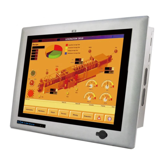
1.1 Overview Figure 1-1: PPC-5152-D525-E Panel PC The fanless PPC-5152-D525-E is Intel® Atom™ D525 powered flat-bezel panel PC with a rich variety of functions and peripherals. The PPC-5152-D525-E panel PC is designed for easy and simplified integration in to various applications. -
Page 15: Features
PPC-5152-D525-E Panel PC 1.2 Features All the PPC-5152-D525-E models feature the following: 15'' 400nits 1024 x 768 LCD with LED backlight 5-wire resistive type touchscreen Fanless system with 1.8GHz Intel® Atom™ D525 dual-core processor Dual gigabit Ethernet port ... -
Page 16: External Overview
The bottom panel provides access to external interface connectors. 1.3.1 Front Panel The front side of the PPC-5152-D525-E is a flat panel TFT LCD screen surrounded by an aluminum frame. Figure 1-2: Front View 1.3.2 Bottom Panel The following is a list of the bottom panel peripheral device connectors on the PPC-5152-D525-E. -
Page 17: Figure 1-3: Bottom View
PPC-5152-D525-E Panel PC 1 x CF Type II slot 2 x Expansion slots for PCI/PCIe expansion modules The bottom panel also includes the following switches and buttons: 1 x Power switch 1 x AT/ATX power mode switch ... -
Page 18: Side Panels
PPC-5152-D525-E Panel PC 1.3.3 Side Panels Both side panels of the flat panel PC have some vents for ventilation and slots for installing the panel mounting clamps ( F igure 1-4). 5 5 4 Figure 1-4: Side View 1.3.4 Top Panel... -
Page 19: Rear Panel
PPC-5152-D525-E Panel PC 1.3.5 Rear Panel The rear panel has retention screw holes that support VESA-mounting compliant wall-mounting brackets, stands or arms. Figure 1-6: Rear View Page 7... -
Page 20: Backplane Options
PPC-5152-D525-E Panel PC 1.4 Backplane Options The backplane option of the PPC-5152-D525-E is shown below. Figure 1-7: Backplane Option (HPE-2S2) The rated voltage and current of the backplane are listed below: Rated Rated Current Voltage +5 V +12 V 2.4 A -12 V 0.1 A... -
Page 21: Dimensions
PPC-5152-D525-E Panel PC 1.5 Dimensions The dimensions of the PPC-5152-D525-E are shown in F igure 1-8 and listed below. 5 5 4 Figure 1-8: PPC-5152-D525-E Dimensions (mm) Page 9... -
Page 22: Specifications
PPC-5152-D525-E Panel PC 1.6 Specifications The technical specifications for the PPC-5152-D525-E system are listed in T able 1-1. 5 5 4 Specification PPC-5152-D525-E LCD Size 15” Max. Resolution 1024 x 768 (XGA) Brightness 400 cd/m Contrast Ratio 500:1 LCD Color 16.2 M... - Page 23 PPC-5152-D525-E Panel PC Expansion Two PCI slots or One PCI slot and one PCIe x1 slot Construction Material Aluminum (front panel) Heavy-duty steel (chassis) Mounting Wall, Panel, Rack, Stand, Arm (VESA 100 mm x 100 mm) Front Panel Color PMS 8401C...
-
Page 24: Table 1-1: System Specifications
PPC-5152-D525-E Panel PC Five serial ports : 2 x DB-9 RS-232 ports 1 x DB-9 RS-232/422/485 port 2 x RJ-45 RS-422/485 ports Four USB ports: 2 x USB 2.0 (I/O panel) 2 x USB 3.0 (I/O panel) 1 x VGA connector... -
Page 25: Power Adapter Specifications
PPC-5152-D525-E Panel PC 1.7 Power Adapter Specifications The specifications of the power adapter that came with the PPC-5152-D525-E are listed T able 1-2. 5 5 4 FSP090-D2BA1 Model Name 90 W Wattage V-Output 19 V Product Highlight O/P Current 4.74 A... -
Page 26: Unpacking
PPC-5152-D525-E Panel PC Chapter Unpacking Page 14... -
Page 27: Unpacking
PPC-5152-D525-E Panel PC 2.1 Unpacking To unpack the flat panel PC, follow the steps below: WARNING! The front side LCD screen has a protective plastic cover stuck to the screen. Only remove the plastic cover after the panel PC has been properly installed. -
Page 28: Packing List
PPC-5152-D525-E Panel PC 2.2 Packing List The PPC-5152-D525-E panel PC is shipped with the following components: Quantity Item Image PPC-5152-D525-E panel PC Power adapter (P/N: 63040-010090-050-RS) Power cord (P/N: 32702-000401-100-RS) RJ-45 to DB-9 COM port cable (P/N: 32005-000700-101-RS) HDD installation screws (M3*4) - Page 29 PPC-5152-D525-E Panel PC User manual CD and driver CD (P/N: IEI-7B000-000732-RS) One Key Recover CD (P/N: IEI-7B000-000724-RS) If any of these items are missing or damaged, contact the distributor or sales representative immediately. Page 17...
-
Page 30: Installation
PPC-5152-D525-E Panel PC Chapter Installation Page 18... -
Page 31: Anti-Static Precautions
Electrostatic discharge (ESD) can cause serious damage to electronic components, including the PPC-5152-D525-E. Dry climates are especially susceptible to ESD. It is therefore critical that whenever the PPC-5152-D525-E is accessed internally, or any other electrical component is handled, the following anti-static precautions are strictly adhered ... -
Page 32: Preinstalled Components
PPC-5152-D525-E Panel PC configure the jumpers or plug in added peripheral devices, ground themselves first and wear and anti-static wristband. 3.3 Preinstalled Components The following components are all preinstalled. Motherboard TFT LCD screen DDR3 memory module ... -
Page 33: Hdd Installation
0: Step 3: 3.5 HDD Installation The PPC-5152-D525-E has one internal HDD bay. To install the HDD, follow the instructions below. Remove a total of 11 retention screws from the back cover, nine on the rear of Step 1: the frame and two on the rear panel ( F igure 3-3). -
Page 34: Figure 3-4: Hdd Bracket Retention Screws
SATA power cable from the motherboard. See F igure 3-4. Figure 3-4: HDD Bracket Retention Screws Lift the HDD bracket out of the PPC-5152-D525-E. Step 3: Insert the HDD to the bracket and connect the HDD to the SATA connector on Step 4: the bracket. -
Page 35: Figure 3-6: Hdd Bracket Installation
PPC-5152-D525-E Panel PC Secure the HDD bracket with the PPC-5152-D525-E by the four retention Step 6: screws that were previously removed ( F igure 3-6). Figure 3-6: HDD Bracket Installation Connect the SATA cable and the SATA power cable to the corresponding Step 7: connectors on the motherboard. -
Page 36: Pci Expansion Card Installation
PPC-5152-D525-E Panel PC 3.6 PCI Expansion Card Installation CAUTION: The maximum dimensions of the expansion card should be 200 mm in length, 100 mm in width and 20 mm in height. The width of the I/O panel should be no more than 73.8 mm. The diagram below shows the dimensions of the expansion slot on the bottom panel of the PPC-5152-D525-E. -
Page 37: Figure 3-7: Pci Expansion Slot Retention Screw
PPC-5152-D525-E Panel PC Figure 3-7: PCI Expansion Slot Retention Screw Insert the expansion card. Align the PCI expansion card edge connector with the Step 3: PCI expansion slot on the PCI riser card. Gently insert the PCI card into the PCI expansion slot. -
Page 38: Pcie Expansion Card Installation (Optional)
PPC-5152-D525-E Panel PC 3.7 PCIe Expansion Card Installation (Optional) CAUTION: The maximum dimensions of the expansion card should be 200 mm in length, 100 mm in width and 20 mm in height. The width of the I/O panel should be no more than 73.8 mm. The diagram below shows the dimensions of the expansion slot on the bottom panel of the PPC-5152-D525-E. -
Page 39: Figure 3-9: Pice Expansion Slot Retention Screw
PPC-5152-D525-E Panel PC Figure 3-9: PICe Expansion Slot Retention Screw Insert the expansion card. Align the PCIe expansion card edge connector with Step 3: the PCIe expansion slot on the PCIe riser card. Gently insert the PCIe card into the PCIe expansion slot. -
Page 40: Mounting The System
Wall mounting The mounting methods are described below. 3.8.1 Arm Mounting The PPC-5152-D525-E can be installed on any arm that supports the standard VESA mounting interface. An example arm is shown below. Figure 3-11: VESA Compliant Arm To install the PPC-5152-D525-E on the arm, follow the directions below. -
Page 41: Figure 3-12: Arm Mounting Retention Screw Holes
PPC-5152-D525-E Panel PC NOTE: Make sure the arm supports standard VESA mounting. The PPC-5152-D525-E uses a VESA mounting to attach to the arm. The arm is purchased separately. Follow the instructions in the arm's user Step 1: manual to securely attach the arm to the wall. -
Page 42: Panel Mounting
PPC-5152-D525-E Panel PC 3.8.2 Panel Mounting To mount the PPC-5152-D525-E flat panel PC into a panel, please follow the steps below. Select the position in the panel to mount the panel PC. Step 1: Cut out a section from the panel that corresponds to the dimensions of the flat Step 2: panel PC chassis. -
Page 43: Figure 3-14: Panel Mounting Clamp Slots (Side View)
PPC-5152-D525-E Panel PC Figure 3-14: Panel Mounting Clamp Slots (Side View) Tighten the screws that pass through the panel mounting clamps until the plastic Step 5: caps at the front of all the screws are firmly secured to the panel ( F igure 3-15). -
Page 44: Rack/Cabinet Mounting
Figure 3-15: Tighten the Panel Mounting Clamp Screws 3.8.3 Rack/Cabinet Mounting The PPC-5152-D525-E panel PC can be installed into a rack or cabinet. The installation procedures are similar to the panel mounting installation. To do this, please follow the steps below:... -
Page 45: Figure 3-16: The Rack/Cabinet Bracket
PPC-5152-D525-E Panel PC Figure 3-16: The Rack/Cabinet Bracket Insert the rack mounting clamps into the pre-formed holes along the edges of Step 2: the panel PC, behind the ABS/PC plastic frame. Tighten the screws that pass through the rack mounting clamps until the plastic... -
Page 46: Stand Mounting
(Figure 3-18). 3.8.4 Stand Mounting The PPC-5152-D525-E can be installed on any stand that supports the standard VESA mounting interface. An example stand is shown below. Figure 3-19: VESA Compliant Stand To install the PPC-5152-D525-E on the stand, follow the directions below. -
Page 47: Wall Mounting
PPC-5152-D525-E Panel PC Locate the screw holes on the rear of the PPC-5152-D525-E. This is where the Step 1: stand bracket will be attached. The stand mount retention screw holes are shown in Figure 3-20. Figure 3-20: Stand Mounting Retention Screw Holes Align the bracket with the screw holes. -
Page 48: Figure 3-21: Wall-Mounting Bracket
PPC-5152-D525-E Panel PC Figure 3-21: Wall-mounting Bracket Insert the four monitor mounting screws provided in the wall mounting kit into the Step 6: four screw holes on the real panel of the flat panel PC and tighten until the screw shank is secured against the rear panel (Figure 3-22). -
Page 49: Figure 3-22: Chassis Support Screws
PPC-5152-D525-E Panel PC Figure 3-22: Chassis Support Screws NOTE: In the diagram below the bracket is already installed on the wall. Secure the panel PC by fastening the retention screw of the wall-mounting Step 9: bracket. (Figure 3-23). Step 0:... -
Page 50: Bottom Panel Connectors
Figure 3-23: Secure the Panel PC 3.9 Bottom Panel Connectors The bottom panel of the PPC-5152-D525-E contains I/O connectors, switches and a CF card slot. Detailed descriptions of the connectors can be found in the subsections below. 3.9.1 LAN Connector The LAN connector allows connection to an external network. -
Page 51: Power Input, Din Connector
PPC-5152-D525-E Panel PC Figure 3-24: RJ-45 Ethernet Connector The RJ-45 Ethernet connector has two status LEDs, one green and one yellow. See F igure 3-24. Description Description on: linked off: 10 Mb/s blinking: data is being sent/received green: 100 Mb/s... -
Page 52: Rs-232/422/485 Serial Port (Com3)
PPC-5152-D525-E Panel PC Figure 3-25: RS-232 Serial Port Description Table 3-3: RS-232 Serial Port Pinouts 3.9.4 RS-232/422/485 Serial Port (COM3) CN Label: COM3 DB-9 connector CN Type: F igure 1-3 CN Location: CN Pinouts: T able 3-4 and F igure 3-26 An RS-232/422/485 device can be connected to the RS-232/422/485 serial port on the bottom panel. -
Page 53: Com3 Mode Select Switch
PPC-5152-D525-E Panel PC Figure 3-26: RS-232/422/485 Serial Port RS-232 RS-422 RS-485 DATA+ DATA- Table 3-4: RS-232/422/485 Serial Port Pinouts 3.9.4.1 COM3 Mode Select Switch Jumper Label: 10-pin DIP switch Jumper Type: T able 3-5 Jumper Settings: Jumper Location: F igure 3-27 The COM3 RS-232/422/485 Serial Port Select jumper sets the communication protocol used by the second serial communications port (COM3) as RS-232, RS-422 or RS-485. -
Page 54: Rs-422/485 Serial Port (Com4, Com5)
PPC-5152-D525-E Panel PC COM3 Mode Settings RS-232 (Default) OFF: 1, 2, 3, 4, 5 ON: 6, 7, 8, 9, 10 RS-422/485 OFF: 6, 7, 8, 9, 10 ON: 1, 2, 3, 4, 5 Table 3-5: COM3 RS-232/422/485 Serial Port Select Settings The COM3 RS-232/422/485 Serial Port Select jumper location is shown in F igure 3-27. -
Page 55: Figure 3-28: Rj-45 Rs-422/485 Serial Port
Step 1: connector is shown in F igure 1-3. Insert the RJ-45 connector. Insert the RJ-45 connector on the RJ-45 to DB-9 Step 2: COM port cable to the RJ-45 RS-422/485 connector on the PPC-5152-D525-E. F igure 3-29. Page 43... -
Page 56: Figure 3-29: Rj-45 Rs-422/485 Serial Device Connection
PPC-5152-D525-E Panel PC Figure 3-29: RJ-45 RS-422/485 Serial Device Connection Insert the serial connector. Insert the DB-9 connector of a serial device into the Step 3: DB-9 connector on the RJ-45 to DB-9 COM port cable. Secure the connector. Secure the serial device connector to the external Step 4: interface by tightening the two retention screws on either side of the connector. -
Page 57: Usb 2.0 Connectors
PPC-5152-D525-E Panel PC RS-422 RS-485 Table 3-7: RS-422/485 Serial Port Pinouts 3.9.6 USB 2.0 Connectors CN Label: USB2.0 USB 2.0 port CN Type: CN Location: F igure 1-3 CN Pinouts: T able 3-8 The USB 2.0 ports are for attaching USB 2.0 peripheral devices to the system. The pinouts of the USB 2.0 port is shown below. -
Page 58: Vga Connector
PPC-5152-D525-E Panel PC The USB 3.0 ports are for attaching USB 3.0 peripheral devices to the system. To be able to use the USB 3.0 ports, please make sure the USB 3.0 function is enabled in BIOS (see Section 5 .3.5). -
Page 59: Power-Up The System
3.10.1 AT/ATX Power Mode Selection The PPC-5152-D525-E supports both AT and ATX power modes. The setting can be made through the AT/ATX power mode switch on the bottom panel as shown below. -
Page 60: Powering On/Off In Atx Power Mode
PPC-5152-D525-E Panel PC 3.10.2 Powering On/Off in ATX Power Mode Power on the system: press the power button for 3 seconds Power off the system: press the power button for 6 seconds Figure 3-33: Power Button Page 48... -
Page 61: System Maintenance
PPC-5152-D525-E Panel PC Chapter System Maintenance Page 49... -
Page 62: System Maintenance Introduction
PPC-5152-D525-E Panel PC 4.1 System Maintenance Introduction If the components of the PPC-5152-D525-E fail they must be replaced. Components that can be replaced include: SO-DIMM module WLAN Module Please contact the system reseller or vendor to purchase the replacement parts. Back cover removal instructions for the PPC-5152-D525-E are described below. -
Page 63: Turn Off The Power
Hold down the power switch for six seconds to power off the system. Step 2: Step 0: 4.4 Opening the System To access the PPC-5152-D525-E internally the back cover must be removed. To remove the back cover, please follow the steps below. Follow all anti-static procedures. See Section Step 1: 4 .2. -
Page 64: Memory Module Replacement
PPC-5152-D525-E Panel PC Remove a total of 11 retention screws from the back cover, nine on the rear of Step 3: the frame and two on the rear panel ( F igure 4-1). Figure 4-1: Back Cover Retention Screws Carefully separate the back cover from the chassis and lift the cover clear of the... -
Page 65: Figure 4-2: Ddr So-Dimm Module Installation
PPC-5152-D525-E Panel PC Install the new DDR3 memory module by pushing it into the socket at an angle Step 7: F igure 4-2). Gently pull the spring retainer clips of the SO-DIMM socket out and push the Step 8: rear of the DDR memory module down ( F igure 4-2). -
Page 66: Ami Bios Setup
PPC-5152-D525-E Panel PC Chapter AMI BIOS Setup Page 54... -
Page 67: Introduction
PPC-5152-D525-E Panel PC 5.1 Introduction The BIOS is programmed onto the BIOS chip. The BIOS setup program allows changes to certain system settings. This chapter outlines the options that can be changed. NOTE: Some of the BIOS options may vary throughout the life cycle of the product and are subject to change without prior notice. -
Page 68: Getting Help
PPC-5152-D525-E Panel PC Function Increase the numeric value or make changes Decrease the numeric value or make changes Page up Move to the next page Page down Move to the previous page Main Menu – Quit and do not save changes into CMOS... -
Page 69: Main
PPC-5152-D525-E Panel PC 5.2 Main The Main BIOS menu ( B IOS Menu 1) appears when the BIOS Setup program is entered. The Main menu gives an overview of the basic system information. Aptio Setup Utility – Copyright (C) 2011 American Megatrends, Inc. -
Page 70: Advanced
PPC-5152-D525-E Panel PC System Time [xx:xx:xx] Use the System Time option to set the system time. Manually enter the hours, minutes and seconds. 5.3 Advanced Use the Advanced menu ( B IOS Menu 2) to configure the CPU and peripheral devices... -
Page 71: Acpi Settings
PPC-5152-D525-E Panel PC 5.3.1 ACPI Settings The ACPI Settings menu ( B IOS Menu 3) configures the Advanced Configuration and Power Interface (ACPI) options. Aptio Setup Utility – Copyright (C) 2011 American Megatrends, Inc. Advanced ACPI Sleep State [S1 (CPU Stop Clock)]... -
Page 72: Rtc Wake Settings
PPC-5152-D525-E Panel PC 5.3.2 RTC Wake Settings The RTC Wake Settings menu ( B IOS Menu 4) configures RTC wake event. Aptio Setup Utility – Copyright (C) 2011 American Megatrends, Inc. Advanced Wake System with Fixed Time [Disabled] Select the highest ACPI... -
Page 73: Cpu Configuration
PPC-5152-D525-E Panel PC If selected, the following appears with values that Enabled can be selected: *Wake up every day *Wake up date *Wake up hour *Wake up minute *Wake up second After setting the alarm, the computer turns itself on from a suspend state when the alarm goes off. -
Page 74: Hyper Threading Function [Enabled]
PPC-5152-D525-E Panel PC Processor Type: Lists the brand name of the CPU being used EMT64: Indicates if EM64T is supported by the CPU. Processor Speed: Lists the CPU processing speed System Bus Speed: Lists the system bus speed ... -
Page 75: Ide Configuration
PPC-5152-D525-E Panel PC 5.3.4 IDE Configuration Use the IDE Configuration menu ( B IOS Menu 6) to change and/or set the configuration of the IDE or SATA devices installed in the system. Aptio Setup Utility – Copyright (C) 2011 American Megatrends, Inc. -
Page 76: Usb Configuration
PPC-5152-D525-E Panel PC Configure SATA as [IDE] Use the Configure SATA as option to configure SATA devices as normal IDE devices. Configures SATA devices as normal IDE device. EFAULT The SATA drive connected to the nth SATA drive port is AHCI specified as a normal SATA drive. -
Page 77: Super Io Configuration
PPC-5152-D525-E Panel PC Legacy USB Support [Enabled] Use the Legacy USB Support BIOS option to enable USB mouse and USB keyboard support. Normally if this option is not enabled, any attached USB mouse or USB keyboard does not become available until a USB compatible operating system is fully booted with all USB drivers loaded. -
Page 78: Serial Port N Configuration
PPC-5152-D525-E Panel PC 5.3.6.1 Serial Port n Configuration Use the Serial Port n Configuration menu ( B IOS Menu 9) to configure the serial port n. Aptio Setup Utility – Copyright (C) 2011 American Megatrends, Inc. Advanced Serial Port 1 Configuration... -
Page 79: Serial Port 1 Mode [Rs232]
PPC-5152-D525-E Panel PC Serial Port I/O port address is 3F8h and the interrupt IO=3F8h; address is IRQ4 IRQ=4 Serial Port I/O port address is 3F8h and the interrupt IO=3F8h; address is IRQ3, 4 IRQ=3, 4 Serial Port I/O port address is 2F8h and the interrupt IO=2F8h;... -
Page 80: Serial Port [Enabled]
PPC-5152-D525-E Panel PC Serial Port 2 Mode [RS232] The Serial Port 2 Mode option is set the Serial Port 2 signaling mode to RS-232 and can not be changed. 5.3.6.1.3 Serial Port 3 Configuration Serial Port [Enabled] Use the Serial Port option to enable or disable the serial port. -
Page 81: Change Settings [Auto]
PPC-5152-D525-E Panel PC 5.3.6.1.4 Serial Port 4 Configuration Serial Port [Enabled] Use the Serial Port option to enable or disable the serial port. Disable the serial port Disabled Enable the serial port Enabled EFAULT Change Settings [Auto] Use the Change Settings option to change the serial port IO port address and interrupt address. -
Page 82: Serial Port 5 Mode [Rs422/485]
PPC-5152-D525-E Panel PC Enable the serial port Enabled EFAULT Change Settings [Auto] Use the Change Settings option to change the serial port IO port address and interrupt address. The serial port IO port address and interrupt address... -
Page 83: H/W Monitor
PPC-5152-D525-E Panel PC 5.3.7 H/W Monitor The H/W Monitor menu ( B IOS Menu 10) shows the operating temperature, fan speeds and system voltages. Aptio Setup Utility – Copyright (C) 2011 American Megatrends, Inc. Advanced PC Health Status :+60 °C CPU Temperature Accuracy:1.(-5~+10)degree around 100 degree... -
Page 84: Serial Port Console Redirection
PPC-5152-D525-E Panel PC 5.3.8 Serial Port Console Redirection The Serial Port Console Redirection menu ( B IOS Menu 11) allows the console redirection options to be configured. Console redirection allows users to maintain a system remotely by re-directing keyboard input and text output through the serial port. -
Page 85: Terminal Type [Ansi]
PPC-5152-D525-E Panel PC Aptio Setup Utility – Copyright (C) 2011 American Megatrends, Inc. Advanced COM1 Console Redirection Console Redirection Settings Enable or Disable Terminal Type [ANSI] Bits per second [115200] --------------------- : Select Screen Data Bits : Select Item... -
Page 86: Iei Feature
PPC-5152-D525-E Panel PC 5.3.9 IEI Feature Use the IEI Feature menu ( B IOS Menu 13) to configure One Key Recovery function. Aptio Setup Utility – Copyright (C) 2011 American Megatrends, Inc. Advanced iEi Feature Auto Recovery Function Reboot and recovery... -
Page 87: Chipset
PPC-5152-D525-E Panel PC 5.4 Chipset Use the Chipset menu ( B IOS Menu 14) to access the Northbridge and Southbridge configuration menus. WARNING! Setting the wrong values for the Chipset BIOS selections in the Chipset BIOS menu may cause the system to malfunction. -
Page 88: Host Bridge Configuration
PPC-5152-D525-E Panel PC 5.4.1 Host Bridge Configuration Use the Host Bridge Configuration menu ( B IOS Menu 15) to configure the Northbridge chipset. Aptio Setup Utility – Copyright (C) 2011 American Megatrends, Inc. Chipset > OnChip VGA Configuration Config On Chip VGA... -
Page 89: Onchip Vga Configuration
PPC-5152-D525-E Panel PC 5.4.1.1 OnChip VGA Configuration Use the OnChip VGA Configuration menu (BIOS Menu 16) to configure the OnChip VGA. Aptio Setup Utility – Copyright (C) 2011 American Megatrends, Inc. Chipset OnChip VGA Configuration Select Share Memory Size. IGD Memory... -
Page 90: South Bridge Configuration
PPC-5152-D525-E Panel PC 5.4.2 South Bridge Configuration Use the South Bridge Configuration menu ( B IOS Menu 17) to configure the Southbridge chipset. Aptio Setup Utility – Copyright (C) 2011 American Megatrends, Inc. Chipset Auto Power Button Function [Enabled] Select AC power state when... - Page 91 PPC-5152-D525-E Panel PC High Definition Audio Controller [Enabled] The High Definition Audio Controller option enables or disables the High Definition (HD) Audio controller. The onboard HD Audio controller is enabled Enabled EFAULT The onboard HD Audio controller is disabled Disabled ...
-
Page 92: Intel Igd Swsci Opregion
PPC-5152-D525-E Panel PC Power Saving Function [Disabled] Use the Power Saving Function option to enable or disable the power saving function to reduce the power consumption when the system is off. Disable power saving function Disabled EFAULT ... -
Page 93: Boot
PPC-5152-D525-E Panel PC DVMT/FIXED Memory [Maximum] Use the DVMT/FIXED Memory option to specify the maximum amount of memory that can be allocated as graphics memory. Configuration options are listed below. 128 MB 256 MB Maximum Default ... -
Page 94: Bootup Numlock State [On]
PPC-5152-D525-E Panel PC Bootup NumLock State [On] Use the Bootup NumLock State BIOS option to specify if the number lock setting must be modified during boot up. Allows the Number Lock on the keyboard to be EFAULT enabled automatically when the computer system boots up. -
Page 95: Security
PPC-5152-D525-E Panel PC UEFI Boot [Disabled] Use the UEFI Boot option to enable or disable to boot from a UEFI device. Enable to boot from a UEFI device. Enabled Disable to boot from a UEFI device. Disabled EFAULT 5.6 Security... -
Page 96: Save & Exit
PPC-5152-D525-E Panel PC 5.7 Save & Exit Use the Save & Exit menu ( B IOS Menu 21) to load default BIOS values, optimal failsafe values and to save configuration changes. Aptio Setup Utility – Copyright (C) 2011 American Megatrends, Inc. - Page 97 PPC-5152-D525-E Panel PC Restore User Defaults Use the Restore User Defaults option to restore the user defaults to all the setup options. Page 85...
-
Page 98: Software Drivers
PPC-5152-D525-E Panel PC Chapter Software Drivers Page 86... -
Page 99: Available Software Drivers
PPC-5152-D525-E Panel PC 6.1 Available Software Drivers NOTE: The content of the CD may vary throughout the life cycle of the product and is subject to change without prior notice. Visit the IEI website or contact technical support for the latest updates. -
Page 100: Figure 6-1: Chipset Driver Screen
PPC-5152-D525-E Panel PC The setup files are extracted as shown in Step 4: F igure 6-1. Figure 6-1: Chipset Driver Screen When the setup files are completely extracted the Welcome Screen in Step 5: F igure 6-2 appears. Click Next to continue. -
Page 101: Figure 6-3: Chipset Driver License Agreement
PPC-5152-D525-E Panel PC The license agreement in F igure 6-3 appears. Step 7: Read the License Agreement. Step 8: Click Yes to continue. Step 9: Figure 6-3: Chipset Driver License Agreement The Read Me file in F igure 6-4 appears. -
Page 102: Figure 6-4: Chipset Driver Read Me File
PPC-5152-D525-E Panel PC Figure 6-4: Chipset Driver Read Me File Setup Operations are performed as shown in Step 12: F igure 6-5. Once the Setup Operations are complete, click Next to continue. Step 13: Figure 6-5: Chipset Driver Setup Operations The Finish screen in F igure 6-6 appears. -
Page 103: Graphics Driver Installation
PPC-5152-D525-E Panel PC Select “Yes, I want to restart this computer now” and click Step 15: Finish.Step 0: Figure 6-6: Chipset Driver Installation Finish Screen 6.4 Graphics Driver Installation To install the Graphics driver, please do the following. Access the driver list. (See Section Step 1: 6 .2) -
Page 104: Figure 6-7: Graphics Driver Read Me File
PPC-5152-D525-E Panel PC Figure 6-7: Graphics Driver Read Me File The installation files are extracted. See Step 6: F igure 6-8. Click Next to continue. Step 7: Figure 6-8: Graphics Driver Setup Files Extracted The Welcome Screen in F igure 6-9 appears. -
Page 105: Figure 6-9: Graphics Driver Welcome Screen
PPC-5152-D525-E Panel PC Figure 6-9: Graphics Driver Welcome Screen The License Agreement in F igure 6-10 appears. Step 10: Click Yes to accept the agreement and continue. Step 11: Figure 6-10: Graphics Driver License Agreement The Read Me file in F igure 6-11 appears. -
Page 106: Figure 6-11: Graphics Driver Read Me File
PPC-5152-D525-E Panel PC Figure 6-11: Graphics Driver Read Me File Setup Operations are performed as shown in Step 14: F igure 6-12. Once the Setup Operations are complete, click Next to continue. Step 15: Figure 6-12: Graphics Driver Setup Operations The Finish screen in F igure 6-13 appears. -
Page 107: Lan Driver Installation
PPC-5152-D525-E Panel PC Figure 6-13: Graphics Driver Installation Finish Screen 6.5 LAN Driver Installation To install the LAN driver, please do the following. Access the driver list. (See Section Step 1: 6 .2) Click “LAN” and select the Realtek folder Step 2: Select the folder which corresponds to the operating system. -
Page 108: Figure 6-14: Lan Driver Welcome Screen
PPC-5152-D525-E Panel PC Figure 6-14: LAN Driver Welcome Screen Click Next to continue. Step 6: The Ready to Install screen in F igure 6-15 appears. Step 7: Click Next to proceed with the installation. Step 8: Figure 6-15: LAN Driver Welcome Screen The program begins to install. -
Page 109: Figure 6-16: Lan Driver Installation
PPC-5152-D525-E Panel PC The installation progress can be monitored in the progress bar shown in Step 10: F igure 6-16. Figure 6-16: LAN Driver Installation When the driver installation is complete, the screen in F igure 6-17 appears. Step 11:... -
Page 110: Touchscreen Driver Installation
PPC-5152-D525-E Panel PC 6.6 Touchscreen Driver Installation To install the touch panel software driver, please follow the steps below. Access the driver list. (See Section Step 1: 6 .2) Click “Touch Screen.” Step 2: Locate the setup file and double click on it. -
Page 111: Figure 6-19: Touchscreen Driver License Agreement
PPC-5152-D525-E Panel PC Figure 6-19: Touchscreen Driver License Agreement Browse for an install location or use the one suggested ( Step 8: F igure 6-20). Click I to continue. Step 9: NSTALL Figure 6-20: Touchscreen Driver Choose Install Location The Install screen appears and displays the progress of the installation (... -
Page 112: Figure 6-21: Touchscreen Driver Installation Screen
PPC-5152-D525-E Panel PC Click N to continue. Step 11: Figure 6-21: Touchscreen Driver Installation Screen When the installation is complete, click F to exit setup. ( Step 12: F igure 6-22). INISH Figure 6-22: Touchscreen Driver Update Complete Page 100... -
Page 113: Calibrating The Touchscreen
PPC-5152-D525-E Panel PC 6.6.1 Calibrating the Touchscreen To calibrate the touchscreen cursor with the motion of the touchscreen pen (or finger), please follow the steps below: Make sure the touchscreen driver is properly installed. Step 1: Locate the PenMount Monitor icon in the bottom right corner of the screen. -
Page 114: Figure 6-25: Configuration Screen
PPC-5152-D525-E Panel PC Figure 6-25: Configuration Screen Double click the PenMount 9000 icon as shown in Step 6: F igure 6-25. The calibration initiation screen in F igure 6-26 appears. Step 7: Select the Standard Calibration button as shown in Step 8: F igure 6-26. -
Page 115: Usb 3.0 Driver Installation
PPC-5152-D525-E Panel PC Figure 6-27: Calibration Screen Follow the instructions. The user is asked touch the screen at five specified Step 10: points after which the screen is calibrated. Step 0: 6.7 USB 3.0 Driver Installation To install the USB 3.0 driver, please follow the steps below. -
Page 116: Figure 6-28: Usb 3.0 Driver Welcome Screen
PPC-5152-D525-E Panel PC Figure 6-28: USB 3.0 Driver Welcome Screen The License Agreement shown in F igure 6-29 appears. Step 6: Click “I accept the terms in the license agreement” to accept and continue. Step 7: Figure 6-29: USB 3.0 Driver License Agreement... -
Page 117: Figure 6-30: Usb 3.0 Driver Installation Screen
PPC-5152-D525-E Panel PC Figure 6-30: USB 3.0 Driver Installation Screen When the installation is complete, click F to exit setup. ( Step 9: F igure 6-31). INISH Figure 6-31: USB 3.0 Driver Update Complete Page 105... -
Page 118: A Bios Configuration Options
PPC-5152-D525-E Panel PC Appendix BIOS Configuration Options Page 106... -
Page 119: Bios Configuration Options
PPC-5152-D525-E Panel PC BIOS Configuration Options Below is a list of BIOS configuration options described in Chapter 6 6 5 BIOS Information .........................57 System Date [xx/xx/xx] ......................57 System Time [xx:xx:xx] .......................58 ACPI Sleep State [S1 (CPU Stop Clock)] ................59 ... - Page 120 PPC-5152-D525-E Panel PC IGD Memory [8 MB]......................77 Restore on AC Power Loss [Last State] ................78 High Definition Audio Controller [Enabled] ..............79 Set Spread Spectrum function [Disabled].................79 WIFI Support [Enabled] .......................79 Auto Dimming Support [Disabled] ..................79 ...
-
Page 121: B Safety Precautions
Appendix PPC-5152-D525-E Panel PC Safety Precautions Page 109... -
Page 122: Safety Precautions
PPC-5152-D525-E Panel PC WARNING: The precautions outlined in this chapter should be strictly followed. Failure to follow these precautions may result in permanent damage to the EP series. B.1 Safety Precautions Please follow the safety precautions outlined in the sections that follow: B.1.1 General Safety Precautions... -
Page 123: Anti-Static Precautions
PPC-5152-D525-E Panel PC B.1.2 Anti-static Precautions WARNING: Failure to take ESD precautions during the installation of the EP series may result in permanent damage to the EP series and severe injury to the user. Electrostatic discharge (ESD) can cause serious damage to electronic components, including the EP series. -
Page 124: Maintenance And Cleaning Precautions
PPC-5152-D525-E Panel PC Outside the European Union - If you wish to dispose of used electrical and electronic products outside the European Union, please contact your local authority so as to comply with the correct disposal method. Within the European Union: ... -
Page 125: Cleaning Tools
PPC-5152-D525-E Panel PC B.2.2 Cleaning Tools Some components in the EP series may only be cleaned using a product specifically designed for the purpose. In such case, the product will be explicitly mentioned in the cleaning tips. Below is a list of items to use when cleaning the EP series. -
Page 126: C Watchdog Timer
PPC-5152-D525-E Panel PC Appendix Watchdog Timer Page 114... - Page 127 PPC-5152-D525-E Panel PC NOTE: The following discussion applies to DOS environment. IEI support is contacted or the IEI website visited for specific drivers for more sophisticated operating systems, e.g., Windows and Linux. The Watchdog Timer is provided to ensure that standalone systems can always recover from catastrophic conditions that cause the CPU to crash.
-
Page 128: Example Program
PPC-5152-D525-E Panel PC NOTE: When exiting a program it is necessary to disable the Watchdog Timer, otherwise the system resets. Example program: ; INITIAL TIMER PERIOD COUNTER W_LOOP: AX, 6F02H ;setting the time-out value BX, 05 ;time-out value is 5 seconds ;... -
Page 129: D Hazardous Materials Disclosure
PPC-5152-D525-E Panel PC Appendix Hazardous Materials Disclosure Page 117... -
Page 130: Hazardous Material Disclosure Table For Ipb Products Certified As Rohs Compliant Under 2002/95/Ec Without Mercury
PPC-5152-D525-E Panel PC D.1 Hazardous Material Disclosure Table for IPB Products Certified as RoHS Compliant Under 2002/95/EC Without Mercury The details provided in this appendix are to ensure that the product is compliant with the Peoples Republic of China (China) RoHS standards. The table below acknowledges the presences of small quantities of certain materials in the product, and is applicable to China RoHS only. - Page 131 PPC-5152-D525-E Panel PC Part Name Toxic or Hazardous Substances and Elements Lead Mercury Cadmium Hexavalent Polybrominated Polybrominated (Pb) (Hg) (Cd) Chromium Biphenyls Diphenyl Ethers (CR(VI)) (PBB) (PBDE) Housing Display Printed Circuit Board Metal Fasteners Cable Assembly Fan Assembly Power Supply...
- Page 132 PPC-5152-D525-E Panel PC 此附件旨在确保本产品符合中国 RoHS 标准。以下表格标示此产品中某有毒物质的含量符 合中国 RoHS 标准规定的限量要求。 本产品上会附有”环境友好使用期限”的标签,此期限是估算这些物质”不会有泄漏或突变”的 年限。本产品可能包含有较短的环境友好使用期限的可替换元件,像是电池或灯管,这些 元件将会单独标示出来。 部件名称 有毒有害物质或元素 铅 汞 镉 六价铬 多溴联苯 多溴二苯醚 (Pb) (Hg) (Cd) (CR(VI)) (PBB) (PBDE) 壳体 显示 印刷电路板 金属螺帽 电缆组装 风扇组装 电力供应组装 电池 O: 表示该有毒有害物质在该部件所有物质材料中的含量均在 SJ/T11363-2006 标准规定的限量要求以下。 X: 表示该有毒有害物质至少在该部件的某一均质材料中的含量超出 SJ/T11363-2006 标准规定的限量要求。...
Need help?
Do you have a question about the PPC-5152-D525-E and is the answer not in the manual?
Questions and answers