Table of Contents
Advertisement
Quick Links
PPC-F08B/F10B-BT Panel PC
PPC-F08B/F10B-BT Panel PC
MODEL:
PPC-F08B/F10B-BT
Industrial Panel PC with Intel® Celeron® Processor J1900,
Touchscreen, Dual PCIe Mini, USB 3.0,
RS-232/422/485, Dual PCIe GbE, 9 V ~ 30 V DC-in
IP 65 Compliant Front Panel and RoHS Compliant
User Manual
Page I
Rev. 1.03 – December 13, 2017
Advertisement
Chapters
Table of Contents

Related Manuals for IEI Technology PPC-F08B


Summary of Contents for IEI Technology PPC-F08B
- Page 1 PPC-F08B/F10B-BT Panel PC PPC-F08B/F10B-BT Panel PC MODEL: PPC-F08B/F10B-BT Industrial Panel PC with Intel® Celeron® Processor J1900, Touchscreen, Dual PCIe Mini, USB 3.0, RS-232/422/485, Dual PCIe GbE, 9 V ~ 30 V DC-in IP 65 Compliant Front Panel and RoHS Compliant...
- Page 2 PPC-F08B/F10B-BT Panel PC Revision Date Version Changes December 13, 2017 1.03 Updated Section 1.9: Specifications Updated Section 2.3: Optional Items Updated Section 3.11.2: Panel Mounting August 8, 2016 1.02 Added Section 3.8: Wireless LAN Module Installation (Optional) June 27, 2016 1.01...
- Page 3 PPC-F08B/F10B-BT Panel PC Copyright COPYRIGHT NOTICE The information in this document is subject to change without prior notice in order to improve reliability, design and function and does not represent a commitment on the part of the manufacturer. In no event will the manufacturer be liable for direct, indirect, special, incidental, or consequential damages arising out of the use or inability to use the product or documentation, even if advised of the possibility of such damages.
- Page 4 PPC-F08B/F10B-BT Panel PC Manual Conventions WARNING Warnings appear where overlooked details may cause damage to the equipment or result in personal injury. Warnings should be taken seriously. CAUTION Cautionary messages should be heeded to help reduce the chance of losing data or damaging the product.
-
Page 5: Table Of Contents
......................5 OTTOM ANEL 1.7 T ......................... 6 ANEL 1.8 D ....................... 7 IMENSIONS 1.8.1 PPC-F08B-BT Dimensions ................7 1.8.2 PPC-F10B-BT Dimensions ................8 1.9 S ......................9 PECIFICATIONS 2 UNPACKING ........................ 11 2.1 U ......................12 NPACKING 2.2 P ...................... - Page 6 PPC-F08B/F10B-BT Panel PC 3.9.4 RS-232 Serial Port Pinouts ................29 3.9.5 RS-232 Serial Port Connection ................ 29 3.10 AT/ATX M ..................31 ELECTION 3.10.1 AT Power Mode ....................31 3.10.2 ATX Power Mode ................... 31 3.11 M ..................32 OUNTING THE YSTEM 3.11.1 Wall Mounting ....................
- Page 7 PPC-F08B/F10B-BT Panel PC 5.3.4 RTC Wake Settings ................... 64 5.3.5 Serial Port Console Redirection ..............65 5.3.6 iEi Feature ....................... 66 5.3.7 CPU Configuration ..................67 5.3.8 IDE Configuration ................... 69 5.3.9 USB Configuration ................... 70 5.4 C ........................71 HIPSET 5.4.1 North Bridge Configuration ................
- Page 8 PPC-F08B/F10B-BT Panel PC 6.2.18 USB Connector (CAM_USB2) ............... 93 6.2.19 Webcam Connector (CAM_USB1) ..............93 6.3 E ............93 XTERNAL NTERFACE ANEL ONNECTORS 6.3.1 Ethernet Connectors (LAN1 & LAN2) ............. 94 6.3.2 Power Connector (CN5) ................94 6.3.3 RS-232 RJ-45 Serial Port (COM1) ..............94 6.3.4 RS-232/422/485 DB-9 Serial Port (COM2) .............
- Page 9 PPC-F08B/F10B-BT Panel PC List of Figures Figure 1-1: PPC-F08B/F10B-BT Series Panel PC ................ 2 Figure 1-2: Front View ........................4 Figure 1-3: PPC-F08B-BT Rear View ..................... 4 Figure 1-4: PPC-F10B-BT Rear View ..................... 5 Figure 1-5: PPC-F08B-BT Bottom Panel..................5 Figure 1-6: PPC-F10B-BT Bottom Panel..................
- Page 10 PPC-F08B/F10B-BT Panel PC Figure 3-23: PPC-F08B-BT Panel Cutout Dimensions .............. 35 Figure 3-24: PPC-F10B-BT Panel Cutout Dimensions .............. 35 Figure 3-25: Tighten the Mounting Clamp Screws ..............36 Figure 3-26: The Rack/Cabinet Bracket ..................37 Figure 3-27: Secure the Rack/Cabinet Bracket ................38 Figure 3-28: Install into a Rack/Cabinet ..................
- Page 11 PPC-F08B/F10B-BT Panel PC List of Tables Table 1-1: Model Variations ......................3 Table 1-2: System Specifications ....................10 Table 2-1: Packing List ......................... 13 Table 2-2: Optional Items ......................15 Table 3-1: RS-232/422/485 Serial Port Pinouts ................27 Table 3-2: RS-232/422/485 Selection Jumper Settings ............. 27 Table 3-3: COM2 Serial Port Pin 9 Setting Jumper Settings ............
- Page 12 PPC-F08B/F10B-BT Panel PC Table 6-23: Power Connector (CN5) Pinouts ................94 Table 6-24: RS-232 RJ-45 Serial Port (COM1) Pinouts .............. 94 Table 6-25: RS-232/422/485 DB-9 Serial Port (COM2) Pinouts ..........95 Table 6-26: USB 3.0 Connectors (USB_CON1) Pinouts ............95 Table 6-27: Preconfigured Jumpers ...................
- Page 13 PPC-F08B/F10B-BT Panel PC List of BIOS Menus BIOS Menu 1: Main ........................53 BIOS Menu 2: Advanced ......................55 BIOS Menu 3: ACPI Settings ....................... 56 BIOS Menu 4: F81866 Super IO Configuration ................57 BIOS Menu 5: Serial Port n Configuration Menu ............... 57 BIOS Menu 6: F81866 H/W Monitor .....................
-
Page 15: Introduction
PPC-F08B/F10B-BT Panel PC Chapter Introduction Page 1... -
Page 16: Overview
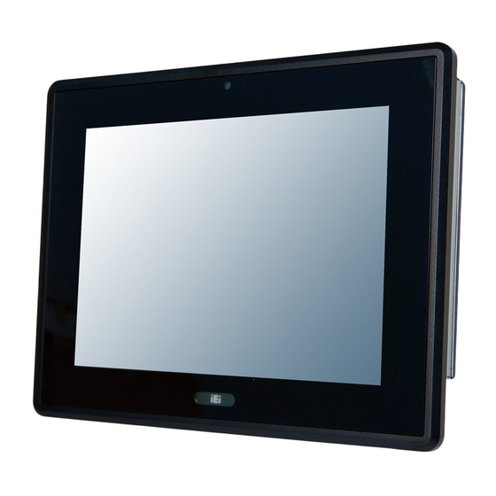
1.1 Overview Figure 1-1: PPC-F08B/F10B-BT Series Panel PC The PPC-F08B/F10B-BT series is a quad-core Intel® Celeron® processor J1900 powered flat bezel panel PC with a rich variety of functions and peripherals. The rugged and trendy design can be applied in harsh industrial environments and enriches aesthetic experience at the same time. -
Page 17: Model Variations
PPC-F08B/F10B-BT Panel PC 1.2 Model Variations The PPC-F08B/F10B-BT series is preinstalled with Intel® Celeron® processor J1900, which has a 10 W TDP. The model numbers and model variations are listed below. Model Size Touchscreen HDD Bay USB 2.0 Ports PPC-F08B-BT-J1/2G/R 8”... -
Page 18: Front Panel
PPC-F08B/F10B-BT Panel PC 1.4 Front Panel The front side of the PPC-F08B/F10B-BT (Figure 1-2) is a flat panel LCD screen surrounded by an aluminum frame. Figure 1-2: Front View 1.5 Rear Panel The rear panel has a fan vent, several VESA mounting holes and retention screws. The VESA mounting holes are circled in the following diagrams. -
Page 19: Bottom Panel
PPC-F08B/F10B-BT Panel PC Figure 1-4: PPC-F10B-BT Rear View 1.6 Bottom Panel The bottom panel has the following interfaces: Figure 1-5: PPC-F08B-BT Bottom Panel Page 5... -
Page 20: Top Panel
PPC-F08B/F10B-BT Panel PC Figure 1-6: PPC-F10B-BT Bottom Panel WARNING: Before installing the operating system, the user must enter the Boot BIOS menu first and choose which operating system will be installed. Otherwise the USB 2.0 and USB 3.0 ports cannot be used for OS installation. -
Page 21: Dimensions
PPC-F08B/F10B-BT Panel PC 1.8 Dimensions 1.8.1 PPC-F08B-BT Dimensions Figure 1-8: PPC-F08B-BT Dimensions (mm) Page 7... -
Page 22: Ppc-F10B-Bt Dimensions
PPC-F08B/F10B-BT Panel PC 1.8.2 PPC-F10B-BT Dimensions Figure 1-9: PPC-F10B-BT Dimensions (mm) Page 8... -
Page 23: Specifications
PPC-F08B/F10B-BT Panel PC 1.9 Specifications The technical specifications for the PPC-F08B/F10B-BT system are listed in Table 1-2. PPC-F08B-BT PPC-F10B-BT LCD Display 8” (4:3) 10.4” (4:3) Max. Resolution 800 (W) x 600 (H) 800 (W) x 600 (H) Brightness 500 cd/m... -
Page 24: Table 1-2: System Specifications
PPC-F08B/F10B-BT Panel PC PPC-F08B-BT PPC-F10B-BT Enclosure Color Black C 2 x GbE (RJ-45) 2 x GbE (RJ-45) 2 x USB 3.0 2 x USB 3.0 2 x USB 2.0 1 x RS-232 (RJ-45) 1 x RS-232 (RJ-45) 1 x RS-232/422/485 (DB-9) -
Page 25: Unpacking
PPC-F08B/F10B-BT Panel PC Chapter Unpacking Page 11... -
Page 26: Unpacking
PPC-F08B/F10B-BT Panel PC 2.1 Unpacking To unpack the panel PC, follow the steps below: WARNING! The front side LCD screen has a protective plastic cover stuck to the screen. Only remove the plastic cover after the panel PC has been properly installed. -
Page 27: Packing List
PPC-F08B/F10B-BT Panel PC 2.2 Packing List The PPC-F08B/F10B-BT panel PC is shipped with the following components: Quantity Item Image PPC-F08B/F10B-BT panel PC Power adapter (36 W, 12 V DC input) Power cord (part number varies by regions) RJ-45 to DB-9 COM port cable... -
Page 28: Optional Items
2.3 Optional Items The following are optional components which may be separately purchased: Item and Part Number Image (P/N: ARM-11-RS) Panel mount kit for PPC-F08B-BT (P/N: FPK-07-R10) Panel mount kit for PPC-F10B-BT (P/N: FPK-09-R10) Stand (P/N:STAND-100-RS) Stand for VESA 75... -
Page 29: Table 2-2: Optional Items
PPC-F08B/F10B-BT Panel PC Item and Part Number Image VESA 75 wall mount kit (P/N: AFLWK-12) Wi-Fi kit (P/N: EMB-WIFI-KIT01-R20) Table 2-2: Optional Items Page 15... -
Page 30: Installation
PPC-F08B/F10B-BT Panel PC Chapter Installation Page 16... -
Page 31: Anti-Static Precautions
Electrostatic discharge (ESD) can cause serious damage to electronic components, including the PPC-F08B/F10B-BT. Dry climates are especially susceptible to ESD. It is therefore critical that whenever the PPC-F08B/F10B-BT is accessed internally, or any other electrical component is handled, the following anti-static precautions are strictly adhered to. -
Page 32: Preinstalled Components
PPC-F08B/F10B-BT Panel PC Mounting: The PPC-F08B/F10B-BT is a heavy device. When mounting the system onto a rack, panel, wall or arm, please make sure that at least two people are assisting with the procedure. Anti-static Discharge: If a user open the rear panel of the panel PC, to configure the jumpers or plug in added peripheral devices, ground themselves first and wear an anti-static wristband. -
Page 33: Removing The
To remove the back cover, remove the back cover retention screws on the back cover. Lift the cover up to remove. The following diagrams show the back cover screw locations of each model. Figure 3-1: PPC-F08B-BT Back Cover Retention Screws Figure 3-2: PPC-F10B-BT Back Cover Retention Screws Page 19... -
Page 34: Msata Module Installation
PPC-F08B/F10B-BT Panel PC 3.6 mSATA Module Installation One of the PCIe Mini card slots on the motherboard of the PPC-F08B/F10B-BT supports mSATA module. To install an mSATA module, please follow the steps below. Step 1: Remove the back cover. See Section 3.5. -
Page 35: Hdd Installation (Ppc-F10B-Bt Only)
PPC-F08B/F10B-BT Panel PC Figure 3-4: mSATA Module Installation Step 5: Replace the back cover and secure it with retention screws. 3.7 HDD Installation (PPC-F10B-BT Only) The PPC-F10B-BT has a 2.5” HDD bay inside the chassis. To install an HDD into the... -
Page 36: Figure 3-5: Ppc-F10B-Bt Hdd Bracket Retention Screws
PPC-F08B/F10B-BT Panel PC Figure 3-5: PPC-F10B-BT HDD Bracket Retention Screws Step 3: Attach the hard drive to the bracket and secure the hard drive to the bracket with four retention screws (Figure 3-6). Figure 3-6: HDD Retention Screws Step 4: Connect the SATA cable and the SATA power cable to the rear of the HDD. -
Page 37: Wireless Lan Module Installation (Optional)
Step 1: Remove the back cover. See Section 3.5. Step 2: Remove the two knockouts for antenna installation. The two knockouts are located on the top panel of the PPC-F08B/F10B-BT. Figure 3-8: Knockouts on Top Panel for Wireless Antennas Page 23... -
Page 38: Figure 3-9: Pcie Mini Slot Location
PPC-F08B/F10B-BT Panel PC Step 3: Locate the PCIe Mini slot (Figure 3-9). Figure 3-9: PCIe Mini Slot Location Step 4: Line up the notch on the WLAN module with the notch on the slot. Slide the WLAN module into the slot at an angle of about 20º (Figure 3-10). -
Page 39: Figure 3-11: Securing Wlan Module
PPC-F08B/F10B-BT Panel PC Step 5: Secure the WLAN module with two retention screws. Figure 3-11: Securing WLAN Module Step 6: Connect the two RF cables to the antenna connectors on the WLAN module (Figure 3-12). Figure 3-12: Connecting RF Cables... -
Page 40: Serial Port Configuration And Connection
Figure 3-13: Securing SMA Connector and External Antenna Installation 3.9 Serial Port Configuration and Connection The PPC-F08B/F10B-BT series has two serial ports, including one RS-232/422/484 port and one RS-232 port. The port locations are shown in Figure 3-14. The jumper settings and pinouts of the serial ports are listed in the following sections. -
Page 41: Rs-232/422/485 Serial Port Pinouts
PPC-F08B/F10B-BT Panel PC 3.9.1 RS-232/422/485 Serial Port Pinouts The RS-232/422/485 serial port pinouts are listed in the following table. RS-232 RS-422 RS-485 Pin No. (COM2) (COM3) (COM3) Data- Data+ Table 3-1: RS-232/422/485 Serial Port Pinouts 3.9.2 RS-232/422/485 Serial Port Selection The JP4 jumper sets the communication protocol used by the DB-9 serial communication port as RS-232, RS-422 or RS-485. -
Page 42: Rs-232/422/485 Serial Port Pin 9 Selection
PPC-F08B/F10B-BT Panel PC The RS-232/422/485 selection jumper location is shown in Figure 3-15. Figure 3-15: RS-232/422/485 Selection Jumper Location 3.9.3 RS-232/422/485 Serial Port Pin 9 Selection The JP5 jumper configures pin 9 on the DB-9 serial port. Pin 9 on the COM2 DB-9 connector can be set as the ring (RI) signal, +5 V or +12 V. -
Page 43: Serial Port Pinouts
The RS-232 port (COM1) is a RJ-45 serial device connector on the bottom panel. The COM1 port connects to a cable with a standard D-sub 9 connector at the other end (cables included). Follow the steps below to connect a serial device to the PPC-F08B/F10B-BT panel PC. -
Page 44: Figure 3-17: Serial Device Connector
PPC-F08B/F10B-BT Panel PC Step 1: Locate the RJ-45 connector. The location of the RJ-45 serial port connector is shown in Chapter 2. The RJ-45 connectors for the serial ports can be identified easily as the RJ-45 for the network has two LEDs on the port, while the connectors for the serial cables don’t. -
Page 45: At/Atx Mode Selection
PPC-F08B/F10B-BT Panel PC 3.10 AT/ATX Mode Selection AT and ATX power modes can both be used on the PPC-F08B/F10B-BT panel PC. The selection is made through an AT/ATX switch on the I/O interface panel. The switch is shown below. Figure 3-18: AT/ATX Mode Selection 3.10.1 AT Power Mode... -
Page 46: Mounting The System
The mounting methods are described in the following sections. 3.11.1 Wall Mounting To mount the PPC-F08B/F10B-BT panel PC onto a wall, please follow the steps below. Step 1: Attach the wall mounting kit to the mounting surface with the included screws. -
Page 47: Figure 3-20: Hook Onto Wall Mounting Kit
Screw the mounting screws to the mounting holes on the rear of the PPC-F08B/F10B-BT. Step 3: Hook the PPC-F08B/F10B-BT into the mounting holes on the wall mounting kit. Figure 3-20: Hook Onto Wall Mounting Kit WARNING: Please use the M4 screws provided in the package for the rear panel. If the screw is missing, the thread depth of the replacement screw should be not more than 4 mm. -
Page 48: Panel Mounting
S t e p 0 : Figure 3-21: Tighten Retention Screw 3.11.2 Panel Mounting To mount the PPC-F08B/F10B-BT panel PC into a panel, please follow the steps below. Step 1: [PPC-F10B-BT Only] Install two mounting brackets onto the rear panel of the PPC-F10B-BT (Figure 3-22). -
Page 49: Figure 3-23: Ppc-F08B-Bt Panel Cutout Dimensions
PPC-F08B/F10B-BT. The recommended cutout sizes are shown below (Figure 3-23 and Figure 3-24). Figure 3-23: PPC-F08B-BT Panel Cutout Dimensions Figure 3-24: PPC-F10B-BT Panel Cutout Dimensions Step 4: Slide the PPC-F08B/F10B-BT through the hole until the aluminum frame is flush against the panel. Page 35... -
Page 50: Figure 3-25: Tighten The Mounting Clamp Screws
PPC-F08B/F10B-BT Panel PC Step 5: Insert the mounting clamps into the mounting brackets and pre-formed holes along the edges of the PPC-F08B/F10B-BT, behind the aluminum frame (Figure 3-25). Step 6: Tighten the screws that pass through the mounting clamps until the plastic caps at the front of all the screws are firmly secured to the panel (Figure 3-25). -
Page 51: Rack Mounting
PPC-F08B/F10B-BT Panel PC 3.11.3 Rack Mounting The PPC-F08B/F10B-BT flat panel PC can be installed into a cabinet or rack. The installation procedures are similar to the panel mounting installation. To do this, please follow the steps below: NOTE: When purchasing the cabinet/rack installation bracket, make sure it is compatible with both the PPC-F08B/F10B-BT flat panel PC and the rack/cabinet into which the PPC-F08B/F10B-BT is installed. -
Page 52: Figure 3-27: Secure The Rack/Cabinet Bracket
(Figure 3-27). Figure 3-27: Secure the Rack/Cabinet Bracket Step 5: Slide the PPC-F08B/F10B-BT with the attached rack/cabinet bracket into a rack or cabinet (Figure 3-28). Figure 3-28: Install into a Rack/Cabinet... -
Page 53: Arm Mounting
Step 2: Once the mounting arm has been firmly attached to its surface, lift the PPC-F08B/F10B-BT panel PC onto the interface pad of the mounting arm. Step 3: Align the retention screw holes on the mounting arm interface with those in the PPC-F08B/F10B-BT panel PC. -
Page 54: Stand Mounting
To mount the PPC-F08B/F10B-BT using the stand mounting kit, please follow the steps below. Step 1: Locate the screw holes on the rear of the PPC-F08B/F10B-BT. This is where the bracket will be attached. The mounting screw holes of the PPC-F08B/F10B-BT panel PC are shown in Figure 1-3 and Figure 1-4. -
Page 55: Powering On The System
Connect the power cord to the power adapter. Connect the other end of the power cord to a power source. Step 2: Connect the power adapter to the power connector of the PPC-F08B/F10B-BT. Step 3: Locate the power button on the I/O panel. -
Page 56: Reset The System
Figure 3-32: Reset Button Location 3.14 Clear CMOS If the PPC-F08B/F10B-BT fails to boot due to improper BIOS settings, the clear CMOS jumper clears the CMOS data and resets the system BIOS information. To do this, push the clear CMOS button for three seconds, then restart the system. To access the clear CMOS button, the back cover must be removed. -
Page 57: Os Installation
PPC-F08B/F10B-BT Panel PC 3.15 OS Installation WARNING: Before installing the operating system, the user must enter the Boot BIOS menu first and choose which operating system will be installed. Otherwise the USB 2.0 and USB 3.0 ports cannot be used for OS installation. -
Page 58: Driver Installation
Visit the IEI website or contact technical support for the latest updates. All the drivers for the PPC-F08B/F10B-BT are on the utility CD that came with the system. The utility CD contains drivers for Windows 7 and Windows 8 operating systems. Please select the corresponding drivers for the system. -
Page 59: Keypad Ap
PPC-F08B/F10B-BT Panel PC 3.16.1 Keypad AP Keypad AP is an OSD control tool developed by IEI. After the installation, the Keypad AP can be accessed by clicking the icon on the notification area. It allows users to control screen brightness and audio volume. -
Page 60: System Maintenance
PPC-F08B/F10B-BT Panel PC Chapter System Maintenance Page 46... -
Page 61: System Maintenance Overview
Failure to follow these instructions may lead to personal injury and system damage. To preserve the working integrity of the PPC-F08B/F10B-BT, the system must be properly maintained. If internal components need replacement, the proper maintenance procedures must be followed to ensure the system can continue to operate normally. -
Page 62: Figure 4-1: So-Dimm Location
PPC-F08B/F10B-BT Panel PC WARNING: Using incorrectly specified SO-DIMM may cause permanently damage the PPC-F08B/F10B-BT. Please make sure the purchased SO-DIMM complies with the memory specifications of the PPC-F08B/F10B-BT. To replace a SO-DIMM into a SO-DIMM socket, please follow the steps below. -
Page 63: Figure 4-2: So-Dimm Installation
PPC-F08B/F10B-BT Panel PC Figure 4-2: SO-DIMM Installation Step 6: Reinstall the back cover. Step 0: Page 49... -
Page 64: Bios Setup
PPC-F08B/F10B-BT Panel PC Chapter BIOS Setup Page 50... -
Page 65: Introduction
PPC-F08B/F10B-BT Panel PC 5.1 Introduction The BIOS is programmed onto the BIOS chip. The BIOS setup program allows changes to certain system settings. This chapter outlines the options that can be changed. NOTE: Some of the BIOS options may vary throughout the life cycle of the product and are subject to change without prior notice. -
Page 66: Getting Help
PPC-F08B/F10B-BT Panel PC Function Increase the numeric value or make changes Decrease the numeric value or make changes Page up Move to the next page Page down Move to the previous page Main Menu – Quit and do not save changes into CMOS... -
Page 67: Bios Menu Bar
PPC-F08B/F10B-BT Panel PC 5.1.5 BIOS Menu Bar The menu bar on top of the BIOS screen has the following main items: Main – Changes the basic system configuration. Advanced – Changes the advanced system settings. Chipset – Changes the chipset settings. -
Page 68: Bios Information
PPC-F08B/F10B-BT Panel PC BIOS Information The BIOS Information lists a brief summary of the BIOS. The fields in BIOS Information cannot be changed. The items shown in the system overview include: BIOS Vendor: Installed BIOS vendor Core Version: Current BIOS version ... -
Page 69: Advanced
PPC-F08B/F10B-BT Panel PC System Time [xx:xx:xx] Use the System Time option to set the system time. Manually enter the hours, minutes and seconds. 5.3 Advanced Use the Advanced menu (BIOS Menu 2) to configure the CPU and peripheral devices... -
Page 70: Acpi Settings
PPC-F08B/F10B-BT Panel PC 5.3.1 ACPI Settings The ACPI Settings menu (BIOS Menu 3) configures the Advanced Configuration and Power Interface (ACPI) options. Aptio Setup Utility – Copyright (C) 2013 American Megatrends, Inc. Advanced ACPI Settings Select the highest ACPI sleep state the system... -
Page 71: F81866 Super Io Configuration
PPC-F08B/F10B-BT Panel PC 5.3.2 F81866 Super IO Configuration Use the F81866 Super IO Configuration menu (BIOS Menu 4) to set or change the configurations for the serial ports. Aptio Setup Utility – Copyright (C) 2013 American Megatrends, Inc. Advanced F81866 Super IO Configuration... -
Page 72: Serial Port [Enabled]
PPC-F08B/F10B-BT Panel PC 5.3.2.1.1 Serial Port 1 Configuration Serial Port [Enabled] Use the Serial Port option to enable or disable the serial port. Disabled Disable the serial port Enable the serial port Enabled EFAULT Change Settings [Auto] Use the Change Settings option to change the serial port IO port address and interrupt address. -
Page 73: Change Settings [Auto]
PPC-F08B/F10B-BT Panel PC Enabled Enable the serial port EFAULT Change Settings [Auto] Use the Change Settings option to change the serial port IO port address and interrupt address. The serial port IO port address and interrupt Auto EFAULT address are automatically detected. -
Page 74: Serial Port [Enabled]
PPC-F08B/F10B-BT Panel PC Auto The serial port IO port address and interrupt EFAULT address are automatically detected. Serial Port I/O port address is 3E8h and the IO=3E8h; IRQ=10 interrupt address is IRQ10 IO=3F8h; Serial Port I/O port address is 3F8h and the... -
Page 75: Serial Port [Enabled]
PPC-F08B/F10B-BT Panel PC IO=2E8h; IRQ=7 Serial Port I/O port address is 2E8h and the interrupt address is IRQ7 Serial Port I/O port address is 3F8h and the IO=3F8h; interrupt address is IRQ3, 4, 5, 6, 7, 9, 10, 11,... -
Page 76: Change Settings [Auto]
PPC-F08B/F10B-BT Panel PC Change Settings [Auto] Use the Change Settings option to change the serial port IO port address and interrupt address. Auto The serial port IO port address and interrupt EFAULT address are automatically detected. Serial Port I/O port address is 2F0h and the IO=2F0h;... -
Page 77: F81866 H/W Monitor
PPC-F08B/F10B-BT Panel PC 5.3.3 F81866 H/W Monitor The F81866 H/W Monitor menu (BIOS Menu 6) shows the operating temperatures and voltages. Aptio Setup Utility – Copyright (C) 2013 American Megatrends, Inc. Advanced PC Health Status CPU temperature :+40 °C System temperature :+41 °C... -
Page 78: Rtc Wake Settings
PPC-F08B/F10B-BT Panel PC 5.3.4 RTC Wake Settings The RTC Wake Settings menu (BIOS Menu 7) configures RTC wake event. Aptio Setup Utility – Copyright (C) 2013 American Megatrends, Inc. Advanced Wake system with Fixed Time [Disabled] Enable or disable System wake on alarm event. -
Page 79: Serial Port Console Redirection
PPC-F08B/F10B-BT Panel PC Enabled If selected, the following appears with values that can be selected: *Wake up every day *Wake up date *Wake up hour *Wake up minute *Wake up second After setting the alarm, the computer turns itself on from a suspend state when the alarm goes off. -
Page 80: Iei Feature
PPC-F08B/F10B-BT Panel PC Console Redirection [Disabled] Use Console Redirection option to enable or disable the console redirection function. Disabled the console redirection function Disabled EFAULT Enabled the console redirection function Enabled 5.3.6 iEi Feature Use the iEi Feature menu (BIOS Menu 9) to configure One Key Recovery function. -
Page 81: Cpu Configuration
PPC-F08B/F10B-BT Panel PC 5.3.7 CPU Configuration Use the CPU Configuration (BIOS Menu 10) to view detailed CPU specifications and configure the CPU. Aptio Setup Utility – Copyright (C) 2013 American Megatrends, Inc. Advanced CPU Configuration When enabled, a VMM can utilize the additional Intel(R) Celeron(R) CPU J1900 @ 1.99GHz... -
Page 82: Intel Virtualization Technology [Disabled]
PPC-F08B/F10B-BT Panel PC L2 Cache: Lists the amount of storage space on the L2 cache. L3 Cache: Lists the amount of storage space on the L3 cache. 64-bit: Indicates if 64-bit OS is supported by the CPU. -
Page 83: Ide Configuration
PPC-F08B/F10B-BT Panel PC 5.3.8 IDE Configuration Use the IDE Configuration menu (BIOS Menu 11) to change and/or set the configuration of the SATA devices installed in the system. Aptio Setup Utility – Copyright (C) 2013 American Megatrends, Inc. Advanced IDE Configuration... -
Page 84: Usb Configuration
PPC-F08B/F10B-BT Panel PC 5.3.9 USB Configuration Use the USB Configuration menu (BIOS Menu 12) to read USB configuration information and configure the USB settings. Aptio Setup Utility – Copyright (C) 2013 American Megatrends, Inc. Advanced USB Configuration Enables Legacy USB support. -
Page 85: Chipset
PPC-F08B/F10B-BT Panel PC Disabled Legacy USB support disabled Legacy USB support disabled if no USB devices are Auto connected 5.4 Chipset Use the Chipset menu (BIOS Menu 13) to access the North Bridge, South Bridge, and Integrated Graphics configuration menus. -
Page 86: North Bridge Configuration
PPC-F08B/F10B-BT Panel PC 5.4.1 North Bridge Configuration Use the North Bridge menu (BIOS Menu 14) to configure the north bridge chipset. Aptio Setup Utility – Copyright (C) 2013 American Megatrends, Inc. Chipset > Intel IGD Configuration Config Intel IGD Settings... -
Page 87: Dvmt Pre-Allocated [256M]
PPC-F08B/F10B-BT Panel PC DVMT Pre-Allocated [256M] Use the DVMT Pre-Allocated option to specify the amount of system memory that can be used by the internal graphics device. 64 MB of memory used by internal graphics device 128 MB of memory used by internal graphics... -
Page 88: South Bridge Configuration
PPC-F08B/F10B-BT Panel PC 5.4.2 South Bridge Configuration Use the South Bridge menu (BIOS Menu 16) to configure the south bridge chipset. Aptio Setup Utility – Copyright (C) 2013 American Megatrends, Inc. Chipset Auto Power Button Status [Disabled (ATX)] Select AC power state... -
Page 89: Xhci Mode [Smart Auto]
PPC-F08B/F10B-BT Panel PC Enabled The High Definition Audio controller is enabled. EFAULT XHCI Mode [Smart Auto] Use the XHCI Mode BIOS option to configure the USB xHCI (USB 3.0) controller. Enable the xHCI controller. USB 3.0 ports behave as Enabled USB 3.0 ports. -
Page 90: Pci Express Configuration
PPC-F08B/F10B-BT Panel PC 5.4.2.1 PCI Express Configuration Use the PCI Express Configuration submenu (BIOS Menu 17) to configure the PCI Express slots. Aptio Setup Utility – Copyright (C) 2013 American Megatrends, Inc. Chipset PCI Express Configuration Configure PCIe Port PCI-E Mini Card (Full Size) -
Page 91: Security
PPC-F08B/F10B-BT Panel PC 5.5 Security Use the Security menu (BIOS Menu 18) to set system and user passwords. Aptio Setup Utility – Copyright (C) 2011 American Megatrends, Inc. Main Advanced Chipset Security Boot Save & Exit Password Description Set Administrator Password If ONLY the Administrator’s password is set,... -
Page 92: Boot
PPC-F08B/F10B-BT Panel PC 5.6 Boot Use the Boot menu (BIOS Menu 19) to configure system boot options. Aptio Setup Utility – Copyright (C) 2013 American Megatrends, Inc. Main Advanced Chipset Security Boot Save & Exit Boot Configuration Select the keyboard... -
Page 93: Quiet Boot [Enabled]
PPC-F08B/F10B-BT Panel PC Quiet Boot [Enabled] Use the Quiet Boot BIOS option to select the screen display when the system boots. Normal POST messages displayed Disabled OEM Logo displayed instead of POST messages Enabled EFAULT UEFI Boot [Disabled] Use the UEFI Boot BIOS option to enable or disable UEFI boot. -
Page 94: Launch Pxe Oprom [Disabled]
PPC-F08B/F10B-BT Panel PC Launch PXE OpROM [Disabled] Use the Launch PXE OpROM option to enable or disable boot option for legacy network devices. Disabled Ignore all PXE Option ROMs EFAULT Load PXE Option ROMs Enabled Option ROM Messages [Force BIOS] Use the Option ROM Messages option to set the Option ROM display mode. -
Page 95: Save & Exit
PPC-F08B/F10B-BT Panel PC 5.7 Save & Exit Use the Save & Exit menu (BIOS Menu 20) to load default BIOS values, optimal failsafe values and to save configuration changes. Aptio Setup Utility – Copyright (C) 2013 American Megatrends, Inc. Main... -
Page 96: Save As User Defaults
PPC-F08B/F10B-BT Panel PC Save as User Defaults Use the Save as User Defaults option to save the changes done so far as user defaults. Restore User Defaults Use the Restore User Defaults option to restore the user defaults to all the setup options. -
Page 97: Interface Connectors
PPC-F08B/F10B-BT Panel PC Chapter Interface Connectors Page 83... -
Page 98: Peripheral Interface Connectors
PPC-F08B/F10B-BT Panel PC 6.1 Peripheral Interface Connectors The PPC-F08B/F10B-BT panel PC motherboard comes with a number of peripheral interface connectors and configuration jumpers. The connector locations are shown in Figure 6-1 and Figure 6-2. The Pin 1 locations of the on-board connectors are also indicated in the diagram below. -
Page 99: Internal Peripheral Connectors
PPC-F08B/F10B-BT Panel PC Figure 6-2: Main Board Layout Diagram (Solder Side) 6.2 Internal Peripheral Connectors Internal peripheral connectors are found on the motherboard and are only accessible when the motherboard is outside of the chassis. The table below shows a list of the peripheral interface connectors on the AFL3MB2-BT. -
Page 100: Battery Connector (Bat1)
PPC-F08B/F10B-BT Panel PC Connector Type Label SATA connector 7-pin connector SATA1 SATA power connector 2-pin wafer SATA_PWR1 Speaker connector 4-pin wafer SPI Flash connector 6-pin wafer JSPI1 TTL serial connector (COM4) 4-pin wafer NFC_CN1 USB 2.0 connector 4-pin wafer HUB_USB1 USB 2.0 connector... -
Page 101: Inverter Connector (Inv_Cn1)
PPC-F08B/F10B-BT Panel PC 6.2.3 Inverter Connector (INV_CN1) PIN NO. DESCRIPTION +12V +12V BLON Brightness Table 6-4: Inverter Connector (INV_CN1) Pinouts 6.2.4 LVDS Connector (LVDS1) PIN NO. DESCRIPTION PIN NO. DESCRIPTION LVDSA0+ LVDSA0- LVDSA1+ LVDSA1- LVDSA2+ LVDSA2- LVDSACLK+ LVDSACLK- LVDSA3+ LVDSA3- Table 6-5: LVDS Connector (LVDS1) Pinouts 6.2.5 MCU Connector (MCU_CN1) -
Page 102: Microphone Connector (Dmic1)
PPC-F08B/F10B-BT Panel PC ICSPDAT Table 6-6: MCU Connector (MCU_CN1) Pinouts 6.2.6 Microphone Connector (DMIC1) PIN NO. DESCRIPTION DMIC_CLK DMIC_DATA +3.3V Table 6-7: Microphone Connector (DMIC1) Pinouts 6.2.7 PCIe Mini Connector, Full-Size (M_PCIE1) PIN NO. DESCRIPTION PIN NO. DESCRIPTION WAKE# VCC3 VCC1.5... -
Page 103: Pcie Mini Connector, Half-Size (M_Pcie2)
PPC-F08B/F10B-BT Panel PC USB_DATA1+ VCC3_AUX VCC3_AUX VCC1.5 Reserved VCC3 Table 6-8: PCIe Mini Connector (M_PCIE1) Pinouts 6.2.8 PCIe Mini Connector, Half-Size (M_PCIE2) PIN NO. DESCRIPTION PIN NO. DESCRIPTION WAKE# VCC3 Reserved Reserved VCC1.5 CLKREQ# REFCLK1- REFCLK1+ PERST# PERn2 VCC3_AUX PERp2 VCC1.5... -
Page 104: Power Led Connector (Pw_Led1)
PPC-F08B/F10B-BT Panel PC VCC3_AUX VCC1.5 Reserved VCC3 Table 6-9: PCIe Mini Connector (M_PCIE2) Pinouts 6.2.9 Power LED Connector (PW_LED1) PIN NO. DESCRIPTION PW_LED +5V SUS PW LED +5V Table 6-10: Power LED Connector (PW_LED1) Pinouts 6.2.10 SATA Connector (SATA1) PIN NO. -
Page 105: Sata Power Connector (Sata_Pwr1)
PPC-F08B/F10B-BT Panel PC 6.2.11 SATA Power Connector (SATA_PWR1) PIN NO. DESCRIPTION Table 6-12: SATA Power Connector (SATA_PWR1) Pinouts 6.2.12 Speaker Connector (CN3) PIN NO. DESCRIPTION AUD_OUTL+ AUD_OUTL- AUD_OUTR- AUD_OUTR+ Table 6-13: Speaker Connector (CN3) Pinouts 6.2.13 SPI Flash Connector (JSPI1) PIN NO. -
Page 106: Usb 2.0 Connector (Hub_Usb1)
PPC-F08B/F10B-BT Panel PC SOUT4 Table 6-15: TTL Serial Connector, COM4 (NFC_CN1) Pinouts 6.2.15 USB 2.0 Connector (HUB_USB1) PIN NO. DESCRIPTION DATA4+ DATA4- Table 6-16: USB 2.0 Connector (HUB_USB1) Pinouts 6.2.16 USB 2.0 Connector (HUB_USB2) PIN NO. DESCRIPTION DATA3+ DATA3- Table 6-17: USB 2.0 Connector (HUB_USB2) Pinouts 6.2.17 VGA Connector (VGA_CON1) -
Page 107: Usb Connector (Cam_Usb2)
PPC-F08B/F10B-BT Panel PC 6.2.18 USB Connector (CAM_USB2) PIN NO. DESCRIPTION DATA3+ DATA3- Table 6-19: USB Connector (CAM_USB2) Pinouts 6.2.19 Webcam Connector (CAM_USB1) PIN NO. DESCRIPTION DATA2+ DATA2- Table 6-20: Webcam Connector (CAM_USB1) Pinouts 6.3 External Interface Panel Connectors The table below lists the rear panel connectors on the AFL2MB-15A motherboard. Pinouts of these connectors can be found in the following sections. -
Page 108: Ethernet Connectors (Lan1 & Lan2)
PPC-F08B/F10B-BT Panel PC 6.3.1 Ethernet Connectors (LAN1 & LAN2) PIN NO. DESCRIPTION PIN NO. DESCRIPTION MDI0+ MDI3- MDI0- +3.3Vsus MDI1+ ACT-1 MDI1- LINNK1000 +3.3sus LINNK1000 +3.3sus MDI2+ MDI2- MDI3+ Table 6-22: Ethernet Connectors (LAN1 & LAN2) Pinouts 6.3.2 Power Connector (CN5) Table 6-23: Power Connector (CN5) Pinouts 6.3.3 RS-232 RJ-45 Serial Port (COM1) -
Page 109: Rs-232/422/485 Db-9 Serial Port (Com2)
SSRX2+ SSTX1- SSTX2- SSTX1+ SSTX2+ Table 6-26: USB 3.0 Connectors (USB_CON1) Pinouts 6.4 Preconfigured Jumper Settings CAUTION: The following jumpers are preconfigured for the PPC-F08B/F10B-BT. Users should not change these jumpers (Table 6-27). It is only for reference. Page 95... -
Page 110: Backlight Voltage Selection Jumper (J_Bl1)
PPC-F08B/F10B-BT Panel PC Jumper Name Type Label Backlight voltage selection 3-pin header J_BL1 Inverter power selection 6-pin header LVDS voltage selection 3-pin header J_VLVDS1 Panel PWM power selection 3-pin header J_ADJ1 Serial port selection 12-pin header Table 6-27: Preconfigured Jumpers 6.4.1 Backlight Voltage Selection Jumper (J_BL1) -
Page 111: Panel Pwm Power Selection Jumper (J_Adj1)
PPC-F08B/F10B-BT Panel PC 6.4.4 Panel PWM Power Selection Jumper (J_ADJ1) DESCRIPTION Short 1-2 +3.3V (Default) Short 2-3 Table 6-31: Panel PWM Power Selection Jumper (J_ADJ1) Settings Page 97... -
Page 112: A Regulatory Compliance
PPC-F08B/F10B-BT Panel PC Appendix Regulatory Compliance Page 98... - Page 113 PPC-F08B/F10B-BT Panel PC DECLARATION OF CONFORMITY This equipment is in conformity with the following EU directives: EMC Directive (2004/108/EC, 2014/30/EU) Low-Voltage Directive (2006/95/EC, 2014/35/EU) RoHS II Directive (2011/65/EU, 2015/863/EU) If the user modifies and/or install other devices in the equipment, the CE conformity declaration may no longer apply.
- Page 114 PPC-F08B/F10B-BT Panel PC Español [Spanish] IEI Integration Corp declara que el equipo cumple con los requisitos esenciales y cualesquiera otras disposiciones aplicables o exigibles de la Directiva 2014/53/EU. Ελληνική [Greek] IEI Integration Corp ΔΗΛΩΝΕΙ ΟΤΙ ΕΞΟΠΛΙΣΜΟΣ ΣΥΜΜΟΡΦΩΝΕΤΑΙ ΠΡΟΣ ΤΙΣ ΟΥΣΙΩΔΕΙΣ ΑΠΑΙΤΗΣΕΙΣ ΚΑΙ ΤΙΣ ΛΟΙΠΕΣ ΣΧΕΤΙΚΕΣ ΔΙΑΤΑΞΕΙΣ ΤΗΣ ΟΔΗΓΙΑΣ...
- Page 115 PPC-F08B/F10B-BT Panel PC Româna [Romanian] IEI Integration Corp declară că acest echipament este in conformitate cu cerinţele esenţiale şi cu celelalte prevederi relevante ale Directivei 2014/53/EU. Slovensko [Slovenian] IEI Integration Corp izjavlja, da je ta opreme v skladu z bistvenimi zahtevami in ostalimi relevantnimi določili direktive 2014/53/EU.
- Page 116 PPC-F08B/F10B-BT Panel PC FCC WARNING This equipment complies with Part 15 of the FCC Rules. Operation is subject to the following two conditions: This device may not cause harmful interference, and This device must accept any interference received, including interference that may cause undesired operation.
- Page 117 PPC-F08B/F10B-BT Panel PC CHINA ROHS The label on the product indicates the estimated “Environmentally Friendly Use Period” (EFUP). This is an estimate of the number of years that these substances would “not leak undergo abrupt change.” This product contain replaceable sub-assemblies/components which have a shorter EFUP such as batteries and lamps.
-
Page 118: B Bios Configuration Options
PPC-F08B/F10B-BT Panel PC Appendix BIOS Configuration Options Page 104... -
Page 119: Bios Configuration Options
PPC-F08B/F10B-BT Panel PC B.1 BIOS Configuration Options Below is a list of BIOS configuration options described in Chapter 5. BIOS Information ......................... 54 CPU Information ........................54 Memory Information ......................54 TXE Information ........................54 System Date [xx/xx/xx] ......................54 System Time [xx:xx:xx] ....................... - Page 120 PPC-F08B/F10B-BT Panel PC XHCI Mode [Smart Auto] ..................... 75 Speed [Auto] ......................... 76 Administrator Password ..................... 77 User Password ........................77 Bootup NumLock State [On] ....................78 Quiet Boot [Enabled] ......................79 UEFI Boot [Disabled] ......................79 OS Selection [Windows 8.x] ....................79 Launch PXE OpROM [Disabled] ..................
-
Page 121: C Safety Precautions
PPC-F08B/F10B-BT Panel PC Appendix Safety Precautions Page 107... -
Page 122: Safety Precautions
Electric shocks can occur if the PPC-F08B/F10B-BT chassis is opened when it is running. To avoid risk of electric shock, this device must only be connected to a supply mains with protective earth. -
Page 123: Anti-Static Precautions
PPC-F08B/F10B-BT and severe injury to the user. Electrostatic discharge (ESD) can cause serious damage to electronic components, including the PPC-F08B/F10B-BT. Dry climates are especially susceptible to ESD. It is therefore critical that whenever the PPC-F08B/F10B-BT is opened and any of the electrical components are handled, the following anti-static precautions are strictly adhered to. -
Page 124: Product Disposal
PPC-F08B/F10B-BT Panel PC C.1.3 Product Disposal CAUTION: Risk of explosion if battery is replaced by an incorrect type. Only certified engineers should replace the on-board battery. Dispose of used batteries according to instructions and local regulations. Outside the European Union–If you wish to dispose of used electrical and electronic products outside the European Union, please contact your local authority so as to comply with the correct disposal method. -
Page 125: Maintenance And Cleaning Precautions
Some components in the PPC-F08B/F10B-BT may only be cleaned using a product specifically designed for the purpose. In such case, the product will be explicitly mentioned in the cleaning tips. Below is a list of items to use when cleaning the PPC-F08B/F10B-BT. ... - Page 126 PPC-F08B/F10B-BT Panel PC cloth is recommended when cleaning the device. Water or rubbing alcohol–A cloth moistened with water or rubbing alcohol can be used to clean the device. Using solvents–The use of solvents is not recommended when cleaning the device as they may damage the plastic parts.
-
Page 127: D Watchdog Timer
PPC-F08B/F10B-BT Panel PC Appendix Watchdog Timer Page 113... - Page 128 PPC-F08B/F10B-BT Panel PC NOTE: The following discussion applies to DOS environment. IEI support is contacted or the IEI website visited for specific drivers for more sophisticated operating systems, e.g., Windows and Linux. The Watchdog Timer is provided to ensure that standalone systems can always recover from catastrophic conditions that cause the CPU to crash.
-
Page 129: Example Program
PPC-F08B/F10B-BT Panel PC NOTE: When exiting a program it is necessary to disable the Watchdog Timer, otherwise the system resets. Example program: ; INITIAL TIMER PERIOD COUNTER W_LOOP: AX, 6F02H ;setting the time-out value BX, 05 ;time-out value is 5 seconds ;... -
Page 130: E Hazardous Materials Disclosure
PPC-F08B/F10B-BT Panel PC Appendix Hazardous Materials Disclosure Page 116... - Page 131 PPC-F08B/F10B-BT Panel PC The details provided in this appendix are to ensure that the product is compliant with the Peoples Republic of China (China) RoHS standards. The table below acknowledges the presences of small quantities of certain materials in the product, and is applicable to China RoHS only.
- Page 132 PPC-F08B/F10B-BT Panel PC 此附件旨在确保本产品符合中国 RoHS 标准。以下表格标示此产品中某有毒物质的含量符 合中国 RoHS 标准规定的限量要求。 本产品上会附有”环境友好使用期限”的标签,此期限是估算这些物质”不会有泄漏或突变”的 年限。本产品可能包含有较短的环境友好使用期限的可替换元件,像是电池或灯管,这些元 件将会单独标示出来。 部件名称 有毒有害物质或元素 铅 汞 镉 六价铬 多溴联苯 多溴二苯 醚 (Pb) (Hg) (Cd) (CR(VI)) (PBB) (PBDE) 壳体 显示 印刷电路板 金属螺帽 电缆组装 风扇组装 电力供应组装 电池 O: 表示该有毒有害物质在该部件所有物质材料中的含量均在 SJ/T 11363-2006 (现由 GB/T 26572-2011 取代) 标准规定的限量要求以下。...
Need help?
Do you have a question about the PPC-F08B and is the answer not in the manual?
Questions and answers