Table of Contents
Advertisement
Quick Links
PPC2-CW123/133-EHL
MODEL:
PPC2-CW123/133-EHL
SPPC2-CW123/133-EHL
Panel PC equips Intel® Celeron® J6412 processor, on-board
8GB memory, HDMI display output, dual 2.5G Ethernet port,
eries
one M.2 M key & one M.2 B key expansion slots, 12~24V DC
input, anti-glare and anti-UV 10-point touchscreen
B/15B/17B/19B-BTi
Rev. 1.00 – June 21, 2023
PC
User Manual
Page i
Advertisement
Table of Contents

Related Manuals for IEI Technology PPC2-CW123-EHL


Summary of Contents for IEI Technology PPC2-CW123-EHL
- Page 1 PPC2-CW123/133-EHL MODEL: PPC2-CW123/133-EHL SPPC2-CW123/133-EHL Panel PC equips Intel® Celeron® J6412 processor, on-board 8GB memory, HDMI display output, dual 2.5G Ethernet port, eries one M.2 M key & one M.2 B key expansion slots, 12~24V DC input, anti-glare and anti-UV 10-point touchscreen B/15B/17B/19B-BTi User Manual Page i...
- Page 2 PPC2-CW123/133-EHL Revision Date Version Changes June 21, 2023 1.00 Initial release Page ii...
- Page 3 PPC2-CW123/133-EHL Safety Instructions Warning! Read the user manual before connecting the system to the power source. Vorsicht! Bitte lesen Sie die Bedienungsanleitung, bevor Sie das System an eine Stromquelle anschließen. Attention! Avant de brancher le système à la source d'alimentation, consultez le mode d'emploi.
- Page 4 PPC2-CW123/133-EHL Warning! Use only the adapter and power cord approved for this system. Use of another type of adapter may risk fire or explosion. Please refer to the user manual for the power adapter specifications. Vorsicht! Nur zugelassene Netzteile und Netzkabel dürfen verwendet werden. Die Benutzung von anderen Netzteilen kann einen Brand oder eine Explosion zur Folge haben.
- Page 5 PPC2-CW123/133-EHL Copyright COPYRIGHT NOTICE The information in this document is subject to change without prior notice in order to improve reliability, design and function and does not represent a commitment on the part of the manufacturer. In no event will the manufacturer be liable for direct, indirect, special, incidental, or consequential damages arising out of the use or inability to use the product or documentation, even if advised of the possibility of such damages.
- Page 6 PPC2-CW123/133-EHL Manual Conventions WARNING Warnings appear where overlooked details may cause damage to the equipment or result in personal injury. Warnings should be taken seriously. CAUTION Cautionary messages should be heeded to help reduce the chance of losing data or damaging the product. NOTE These messages inform the reader of essential but non-critical information.
-
Page 7: Table Of Contents
......................4 ANEL 1.6 B ......................5 OTTOM ANEL 1.7 D ....................... 7 IMENSIONS 1.7.1 PPC2-CW123-EHL Dimensions ................ 7 1.7.2 PPC2-CW133-EHL Dimensions ................ 8 1.8 S ......................8 PECIFICATIONS 2 UNPACKING ........................ 11 2.1 U ......................12 NPACKING 2.2 P ...................... - Page 8 PPC2-CW123/133-EHL 3.9.1 RS-232 Serial Ports ..................32 3.9.2 RS-232/422/485 Serial Port ................33 3.10 P ..................33 OWERING ON THE YSTEM 3.11 R ....................34 ESET THE YSTEM 3.12 C CMOS ......................35 LEAR 3.13 A ....................36 VAILABLE RIVERS 3.13.1 Driver Download ...................
- Page 9 PPC2-CW123/133-EHL 5.3.7 Serial Port Console Redirection ..............67 5.3.7.1 Console Redirection Settings ..............68 5.3.8 NVMe Configuration ..................71 5.4 C ........................71 HIPSET 5.4.1 System Agent (SA) Configuration ..............73 5.4.1.1 Memory Configuration ................74 5.4.1.2 Graphics Configuration ................74 5.4.2 PCH-IO Configuration ..................
- Page 10 PPC2-CW123/133-EHL 6.2.15 Chassis intrusion (CHASSIS1) ..............101 6.2.16 Debug port (DBG_PORT1) ................. 101 6.2.17 Power button connector (PWR_BTN1) ............102 6.3 E ............102 XTERNAL NTERFACE ANEL ONNECTORS 6.3.1 HDMI Connector (HDMI1) ................102 6.3.2 2.5GbE Connector (LAN1, LAN2) ..............103 6.3.3 USB 2.0 Connectors (USB2_CON1) ..............
- Page 11 List of Figures Figure 1-1: PPC2-CW123/133-EHL Panel PC ................2 Figure 1-2: Front View ........................4 Figure 1-3: PPC2-CW123-EHL Rear View ..................4 Figure 1-4: PPC2-CW133-EHL Rear View ..................5 Figure 1-5: PPC2-CW123-EHL Bottom View ................5 Figure 1-6: PPC2-CW133-EHL Bottom View ................6 Figure 1-7: PPC2-CW123-EHL Dimensions (mm) ................
- Page 12 PPC2-CW123/133-EHL Figure 3-24: Power Input Connector Pinouts ................33 Figure 3-25: Power Connectors and Power Switch ..............34 Figure 3-26: Reset Button Location ....................34 Figure 3-27: Clear CMOS Button Location .................35 Figure 3-28: IEI Resource Download Center ................36 Figure 5-1: BIOS Starting Menu ....................42 Figure 6-1: Main Board Layout Diagram (Front Side) ...............93 Figure 6-2: Main Board Layout Diagram (Solder Side) .............93 Page xii...
- Page 13 PPC2-CW123/133-EHL List of Tables Table 1-1: Model Variation ......................3 Table 1-2: PPC2-CW123/ PPC2-CW133 Specifications .............10 Table 2-1: Packing List .........................13 Table 3-1: AT/ATX Mode Selection .....................20 Table 3-2: RS-232 Serial Port Pinouts ..................32 Table 3-3: RS-232/422/485 Serial Port (COM3) Pinouts ............33 Table 5-1: BIOS Navigation Keys ....................43 Table 5-2: BIOS On-screen Navigation Keys ................44 Table 6-1: Peripheral Interface Connectors ................94...
-
Page 14: Introduction
PPC2-CW123/133-EHL Chapter Introduction Page 1... -
Page 15: Overview
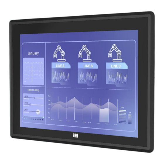
PPC2-CW123/133-EHL 1.1 Overview Figure 1-1: PPC2-CW123/133-EHL Panel PC The PPC2-CW123/133-EHL is a quad-core Intel® Celeron® processor J6412 powered flat bezel panel PC with a rich variety of functions and peripherals. The rugged and trendy design can be applied in harsh industrial environments and enriches aesthetic experience at the same time. -
Page 16: Model Variation
The PPC2-CW123/133-EHL is preinstalled with Intel® Celeron® processor J6412, which has a 10 W TDP. The model numbers and model variations are listed below. Model Size I/O Port PPC2-CW123-EHL-J1/8G-R10 4 x USB, 2 x COM 12.3” PPC2-CW133-EHL-J1/8G-R10 13.3” 4 x USB, 3 x COM Table 1-1: Model Variation 1.3 Features... -
Page 17: Front Panel
Figure 1-2: Front View 1.5 Rear Panel The rear panel has a fan vent, four VESA 75/100 mounting holes and several retention screws. The VESA 75/100 mounting holes are circled in Figure 1-3. Figure 1-3: PPC2-CW123-EHL Rear View Page 4... -
Page 18: Bottom Panel
PPC2-CW123/133-EHL Figure 1-4: PPC2-CW133-EHL Rear View 1.6 Bottom Panel The bottom panel has the following interfaces: Figure 1-5: PPC2-CW123-EHL Bottom View Page 5... -
Page 19: Figure 1-6: Ppc2-Cw133-Ehl Bottom View
PPC2-CW123/133-EHL Figure 1-6: PPC2-CW133-EHL Bottom View Page 6... -
Page 20: Dimensions
PPC2-CW123/133-EHL 1.7 Dimensions 1.7.1 PPC2-CW123-EHL Dimensions Figure 1-7: PPC2-CW123-EHL Dimensions (mm) Page 7... -
Page 21: Ppc2-Cw133-Ehl Dimensions
PPC2-CW123/133-EHL 1.7.2 PPC2-CW133-EHL Dimensions Figure 1-8: PPC2-CW133-EHL Dimensions (mm) 1.8 Specifications The technical specifications are listed in Table 1-2. Page 8... - Page 22 PPC2-CW123/133-EHL PPC2-CW123 PPC2-CW133 LCD Display 12.3" (8:3) 13.3" (16:9) Max. Resolution 1920 x 720 1920 x1080 Brightness 850 cd/m² 400 cd/m2 Contrast Ratio 1000:1 800:1 LCD Color 16.7M 16.7M Pixel Pitch (Unit: mm) 0.152 x 0.152 0.153 x 0.153 Viewing Angle (H-V) 160°/170°...
-
Page 23: Table 1-2: Ppc2-Cw123/ Ppc2-Cw133 Specifications
PPC2-CW123/133-EHL PPC2-CW123 PPC2-CW133 Dimensions 323.43 x 147.91 x 52.5 327.70 x 203.33 x 61.50 (H x W x D) (Unit: mm) Net Weight 2.03kg 2.57kg 1 x HDMI output 1 x HDMI output 2 x RJ-45 GbE 2 x RJ-45 GbE 2 x USB 3.2 Gen 2x1 (10Gb/s) 2 x USB 3.2 Gen 2x1 (10Gb/s) 2 x USB 2.0... -
Page 24: Unpacking
PPC2-CW123/133-EHL Chapter Unpacking Page 11... -
Page 25: Unpacking
PPC2-CW123/133-EHL 2.1 Unpacking To unpack the panel PC, follow the steps below: WARNING! The front side LCD screen has a protective plastic cover stuck to the screen. Only remove the plastic cover after the panel PC has been properly installed. This ensures the screen is protected during the installation process. -
Page 26: Packing List
PPC2-CW123/133-EHL 2.2 Packing List The PPC2-CW123/133-EHL panel PC is shipped with the following components: Quantity Item Image PPC2-CW123/133-EHL panel PC Power cord (part number varies by regions) Power adapter Screw pack Panel mount kit pack Table 2-1: Packing List If any of the above items are missing or damaged, contact the distributor or sales representative immediately. -
Page 27: Installation
PPC2-CW123/133-EHL Chapter Installation Page 14... -
Page 28: Anti-Static Precautions
PPC2-CW123/133-EHL 3.1 Anti-static Precautions WARNING: Failure to take ESD precautions during the maintenance of the panel PC may result in permanent damage to the panel PC and severe injury to the user. Electrostatic discharge (ESD) can cause serious damage to electronic components, including the PPC2-CW123/133-EHL. -
Page 29: Preinstalled Components
PPC2-CW123/133-EHL When installing the panel PC, please follow the precautions listed below: ▪ Power turned off: When installing the panel PC, make sure the power is off. Failing to turn off the power may cause severe injury to the body and/or damage to the system. -
Page 30: Removing The
Configure the system. 3.5 Removing the Back Cover Remove the back cover retention screws on the back cover. Lift the cover up to remove. Figure 3-1:PPC2-CW123-EHL Back Cover Retention Screws Figure 3-2: PPC2-CW133-EHL Back Cover Retention Screws 3.6 M.2 Module Installation (Optional) The M.2 M-key slot allows installation of M.2 2280 cards. -
Page 31: Figure 3-3: M.2 Slot Location
PPC2-CW123/133-EHL Step 1: Remove the back cover. See Section 3.5. 557 H Step 2: Locate the M.2 slot as shown in Figure 3-3. Figure 3-3: M.2 Slot Location Step 3: Press the end of the M.2 retaining clip. As shown in Figure 3-4. Figure 3-4: Press the end of the M.2 retaining clip Step 4: Insert M.2 card. -
Page 32: Figure 3-5: Insert M.2 Card
PPC2-CW123/133-EHL Figure 3-5: Insert M.2 Card Step 5: Secure the M.2 card. Press down the M.2 card to fix it (Figure 3-6). Figure 3-6: Securing the M.2 card Page 19... -
Page 33: At/Atx Mode Selection
PPC2-CW123/133-EHL 3.7 AT/ATX Mode Selection AT and ATX power modes can both be used on the PPC2-CW123/133-EHL panel PC. The selection is made through an AT/ATX switch on the I/O interface panel. The system is set to ATX mode by default. The switch is shown below. Figure 3-7: AT/ATX Mode Selection AT/ATX Switch ATX (Default) -
Page 34: Mounting The System
PPC2-CW123/133-EHL 3.8 Mounting the System WARNING! When mounting the PPC2-CW123/133-EHL panel PC, it is advisable to have more than one person help with the installation to prevent accidental damage to the panel and avoid personal injury. The methods of mounting the PPC2-CW123/133-EHL are: ▪... -
Page 35: Figure 3-8: Wall-Mounting Bracket
PPC2-CW123/133-EHL Figure 3-8: Wall-mounting Bracket Step 6: Insert the four monitor mounting screws provided in the wall mounting kit into the four screw holes on the real panel of the monitor and tighten until the screw shank is secured against the rear panel (Figure 3-9). Step 7: Align the mounting screws on the monitor rear panel with the mounting holes on the bracket. -
Page 36: Figure 3-9: Mount The Chassis
PPC2-CW123/133-EHL Figure 3-9: Mount the Chassis Step 9: Secure the panel PC with the wall-mounting kit. To do this, stick the protective cushion to the wall-mounting kit first. Then, put the wall-mounting kit on the top panel of the panel PC. Carefully mark the location of the wall-mounting kit screw holes on the wall. -
Page 37: Figure 3-10: Secure The Chassis
PPC2-CW123/133-EHL Figure 3-10: Secure the Chassis Page 24... -
Page 38: Panel, Rack And Cabinet Installation
PPC2-CW123/133-EHL 3.8.2 Panel, Rack and Cabinet Installation To mount the PPC2-CW123/133-EHL panel PC into a panel, please follow steps 1-5. For rack and cabinet installation, please follow Steps 1-7. NOTE: For the PPC-XXX-EHL Series panel PC, all mounting kit must be installed (Figure 3-11). -
Page 39: Figure 3-12: Ppc2-Cw123-Ehl Panel Cutout Dimensions
PPC2-CW123/133-EHL Figure 3-12: PPC2-CW123-EHL Panel Cutout Dimensions Figure 3-13: PPC2-CW133-EHL Panel Cutout Dimensions Step 3: Slide the PPC2-CW123/133-EHL through the hole until the aluminum frame is flush against the panel (Figure 3-14). Page 26... -
Page 40: Figure 3-14: Machine Mounted To Panel
PPC2-CW123/133-EHL Figure 3-14: Machine mounted to panel Step 4: Insert the panel mount kit into the prefabricated holes along the rear edge of the PPC2-CW123/133-EHL (Figure 3-15). The required number of mounting clamps may vary by models. Figure 3-15: Installation Panel Mount Kit Page 27... -
Page 41: Figure 3-16: Tighten The Mounting Screws
PPC2-CW123/133-EHL Step 5: Tighten the screws that pass through the mounting clamps until the plastic caps at the front of all the screws are firmly secured to the panel (Figure 3-16). Figure 3-16: Tighten the Mounting Screws Step 6: Slide the PPC2-CW123/133-EHL with the attached rack/cabinet bracket into a rack or cabinet (Figure 3-17). -
Page 42: Arm Mounting
PPC2-CW123/133-EHL Step 7: Once the flat panel PC with the attached rack/cabinet bracket has been properly inserted into the rack or cabinet, secure the front of the rack/cabinet bracket to the front of the rack or cabinet. 3.8.3 Arm Mounting The PPC2-CW123/133-EHL is VESA (Video Electronics Standards Association) compliant and can be mounted on an arm with a 75/100 mm interface pad. -
Page 43: Stand Mounting
PPC2-CW123/133-EHL Figure 3-18: Arm Mounting Retention Screw Holes Step 4: Secure the PPC2-CW123/133-EHL to the interface pad by inserting four retention screws through the mounting arm interface pad and into the PPC2-CW123/133-EHL panel PC. Step 0: Figure 3-19: Arm Mounting (ARM-XX-RS) 3.8.4 Stand Mounting To mount the PPC2-CW123/133-EHL using the stand mounting kit, please follow the steps below. -
Page 44: Serial Device Connection
PPC2-CW123/133-EHL Step 1: Locate the screw holes on the rear of the PPC2-CW123/133-EHL. This is where the bracket will be attached. Figure 3-20: Stand Mounting Retention Screw Holes Step 2: Align the bracket with the screw holes. Step 3: To secure the bracket to the PPC2-CW123/133-EHL, insert the retention screws into the screw holes and tighten them.S t e p 0 : Figure 3-21: Stand Mounting (Stand-Cxx) -
Page 45: Serial Ports
PPC2-CW123/133-EHL Figure 3-22: Serial Port Locations of PPC2-CW123-EHL Figure 3-23: Serial Port Locations of PPC2-CW133-EHL 3.9.1 RS-232 Serial Ports The pinouts of the RS-232 serial ports are listed in the following table. PIN NO. DESCRIPTION PIN NO. DESCRIPTION Table 3-2: RS-232 Serial Port Pinouts... -
Page 46: Rs-232/422/485 Serial Port
PPC2-CW123/133-EHL 3.9.2 RS-232/422/485 Serial Port The pinouts of the RS-232/422/485 serial ports are listed in the following table. PIN NO. RS-232 RS-422 RS-485 TXD422- TXD485- TXD422+ TXD485+ RXD422+ RXD422- Table 3-3: RS-232/422/485 Serial Port (COM3) Pinouts 3.10 Powering on the System To power on the system, follow the steps below: Step 1: Either connect the power adapter to the power jack or connect the power cable... -
Page 47: Reset The System
PPC2-CW123/133-EHL Figure 3-25: Power Connectors and Power Switch 3.11 Reset the System The reset button enables users to reboot the system when the system is turned on. The reset button location is shown in Figure 3-26. Press the reset button to reboot the system. Figure 3-26: Reset Button Location Page 34... -
Page 48: Clear Cmos
PPC2-CW123/133-EHL 3.12 Clear CMOS If the PPC2-CW123/133-EHL fails to boot due to improper BIOS settings, the clear CMOS button clears the CMOS data and resets the system BIOS information. To do this, push the clear CMOS button for three seconds, and then restart the system. The clear CMOS button location is shown in Figure 3-27. -
Page 49: Available Drivers
PPC2-CW123/133-EHL 3.13 Available Drivers All the drivers for the PPC2-CW123/133-EHL are available on IEI Resource Download Center (https://download.ieiworld.com). Type PPC2-CW123/133-EHL and press Enter to find all the relevant software, utilities, and documentation. Figure 3-28: IEI Resource Download Center The following drivers can be installed on the Windows 10/11 operating system: ▪... -
Page 50: Driver Download
PPC2-CW123/133-EHL 3.13.1 Driver Download To download drivers from IEI Resource Download Center, follow the steps below. Step 1: Go to https://download.ieiworld.com. Type PPC2-CW123/133-EHL and press Enter. Step 2: All product-related software, utilities, and documentation will be listed. You can choose Driver to filter the result. Step 3: Click the driver file name on the page and you will be prompted with the ... - Page 51 PPC2-CW123/133-EHL NOTE: To install software from the downloaded ISO image file in Windows 10 or 11, double-click the ISO file to mount it as a virtual drive to view its content. Page 38...
-
Page 52: System Maintenance
PPC2-CW123/133-EHL Chapter System Maintenance Page 39... -
Page 53: System Maintenance Introduction
PPC2-CW123/133-EHL 4.1 System Maintenance Introduction The following system components may require maintenance. ▪ Motherboard ▪ Storage module If these components fail, they must be replaced. Please contact the system reseller or vendor to purchase replacement parts. Replacement instructions for the above listed components are described below. -
Page 54: Bios
PPC2-CW123/133-EHL Chapter BIOS Page 41... -
Page 55: Introduction
PPC2-CW123/133-EHL 5.1 Introduction The BIOS is programmed onto the BIOS chip. The BIOS setup program allows changes to certain system settings. This chapter outlines the options that can be changed. NOTE: Some of the BIOS options may vary throughout the life cycle of the product and are subject to change without prior notice. -
Page 56: Using Setup
PPC2-CW123/133-EHL 5.1.2 Using Setup The BIOS Setup menu can be navigated by using a keyboard or a touchscreen. 5.1.2.1 Keyboard Navigation For keyboard navigation, use the navigation keys shown in Table 5-1. Function Up arrow Move to previous item Down arrow Move to next item Left arrow Move to the item on the left hand side... -
Page 57: Touch Navigation
PPC2-CW123/133-EHL 5.1.2.2 Touch Navigation For touchscreen navigation, use the on-screen navigation keys shown below. On-screen Button Function Previous Values Load the last value you set. Optimized Defaults Load the factory default values in order to achieve the best performance. Back Return to the previous menu. -
Page 58: Getting Help
PPC2-CW123/133-EHL 5.1.3 Getting Help When F1 is pressed a small help window describing the appropriate keys to use and the possible selections for the highlighted item appears. To exit the Help Window, press the key. 5.1.4 Unable to Reboot after Configuration Changes If the computer cannot boot after changes to the system configuration is made, CMOS defaults. -
Page 59: Main
PPC2-CW123/133-EHL 5.2 Main The Main BIOS menu appears when the BIOS Setup program is entered. The Main menu gives an overview of the basic system information. BIOS Menu 1: Main (1/3) BIOS Menu 2: Main (2/3) Page 46... - Page 60 PPC2-CW123/133-EHL BIOS Menu 3: Main (3/3) ➔ BIOS Information The BIOS Information lists a brief summary of the BIOS. The fields in BIOS Information cannot be changed. The items shown in the system overview include: ▪ BIOS Vendor: Installed BIOS vendor ▪...
-
Page 61: Advanced
PPC2-CW123/133-EHL Name: Displays the Processor Details Type: Displays the Processor Type Speed: Displays the Processor Speed ID: Displays the Processor ID Stepping: Displays the Processor Stepping Number of Processors: Displays number of CPU cores Microcode Revision: CPU Microcode Revision IGFX GOP Version: Displays the IGFX GOP Version Total Memory: Total Memory in the System Memory Data Rate: Displays the Rate of Memory Data ➔... -
Page 62: Case Open Detection
PPC2-CW123/133-EHL BIOS Menu 4: Advanced 5.3.1 Case Open Detection ➔ Case Open Detection [Disabled] When the Case Open Detection is enabled, if anyone opens the computer's chassis, or case, Windows will notify the user with a pop-up message the next time he turns on his computer. -
Page 63: Cpu Configuration
PPC2-CW123/133-EHL 5.3.2 CPU Configuration Use the CPU Configuration menu to view detailed CPU specifications or enable the Intel Virtualization Technology. BIOS Menu 5: CPU Configuration (1/3) BIOS Menu 5: CPU Configuration (2/3) Page 50... - Page 64 PPC2-CW123/133-EHL BIOS Menu 6: CPU Configuration (3/3) ➔ Intel (VMX) Virtualization Technology [Enabled] Use the Intel (VMX) Virtualization Technology option to enable or disable virtualization on the system. When combined with third party software, Intel® Virtualization technology allows several OSs to run on the same system at the same time. ➔...
- Page 65 PPC2-CW123/133-EHL ➔ EIST [Enable] Use the EIST option to enable more than two frequency ranges to be supported. ➔ Disabled Disables more than two frequency ranges ➔ Enabled Enables more than two frequency ranges EFAULT ➔ C states [Disabled] Use the C states option to enable or disable the CPU Power Management. ➔...
- Page 66 PPC2-CW123/133-EHL ➔ Tcc Activation Offset [Enabled] Use the Tcc Activation option to set Tcc activation temperature at which the Thermal Control Circuit must be activated. Tcc will be activated at: Tcc Activation Temp-Tcc Activation Offset. Tcc Activation Offset range is 0 to 63. ➔...
-
Page 67: Trusted Computing
PPC2-CW123/133-EHL 5.3.3 Trusted Computing Use the Trusted Computing menu (BIOS Menu 7) to configure settings related to the Trusted Computing Group (TCG) Trusted Platform Module (TPM). BIOS Menu 7: Trusted Computing ➔ TPM Support [Enable] Use the TPM Support option to enable or disable BIOS support for security device. ➔... -
Page 68: Rtc Wake Setting
PPC2-CW123/133-EHL ➔ None TPM information is previous.S EFAULT ➔ TPM Clear TPM information is cleared 5.3.4 RTC Wake Setting The RTC Wake Settings menu (BIOS Menu 8) configures RTC wake event. BIOS Menu 8: RTC Wake Settings ➔ Wake system with Fixed Time [Enabled] Use the Wake system with Fixed Time option to enable or disable the system wake on alarm event. - Page 69 PPC2-CW123/133-EHL ➔ Enabled If selected, the Wake up every day option appears EFAULT allowing you to enable to disable the system to wake every day at the specified time. Besides, the following options appear with values that can be selected: Wake up date Wake up hour Wake up minute...
-
Page 70: F81966 Super Io Configuration
PPC2-CW123/133-EHL 5.3.5 F81966 Super IO Configuration Use the F81966 Super IO Configuration menu (BIOS Menu 9) to set or change the configurations for serial ports. BIOS Menu 9: F81966 Super IO Configuration Page 57... -
Page 71: Serial Port 1 Configuration
PPC2-CW123/133-EHL 5.3.5.1 Serial Port 1 Configuration Use the Serial Port 1 Configuration menu (BIOS Menu 10) to configure the serial port. BIOS Menu 10: Serial Port 1 Configuration Menu ➔ Serial Port [Enabled] Use the Serial Port option to enable or disable the serial port. ➔... - Page 72 PPC2-CW123/133-EHL ➔ IO=3F8h; Serial Port I/O port address is 3F8h and the interrupt IRQ=4 address is IRQ4 ➔ Device Mode [RS232] Use the Device Mode option to change the serial port mode. ➔ RS232 The serial port mode is RS-232 EFAULT RS422 with Register The serial port mode is RS-422...
-
Page 73: Serial Port 2 Configuration
PPC2-CW123/133-EHL 5.3.5.2 Serial Port 2 Configuration Use the Serial Port 2 Configuration menu (BIOS Menu 11) to configure the serial port. BIOS Menu 11: Serial Port 2 Configuration Menu ➔ Serial Port [Enabled] Use the Serial Port option to enable or disable the serial port. ➔... -
Page 74: Serial Port 4 Configuration
PPC2-CW123/133-EHL ➔ IO=2F8h; Serial Port I/O port address is 2F8h and the interrupt IRQ=3 address is IRQ3 5.3.5.3 Serial Port 4 Configuration Use the Serial Port 4 Configuration menu (BIOS Menu 12) to configure the serial port. BIOS Menu 12: Serial Port 4 Configuration Menu ➔... -
Page 75: Serial Port 5 Configuration
PPC2-CW123/133-EHL ➔ Device Settings The Device Settings option shows the serial port IO port address and interrupt address. ➔ IO=2E8h; Serial Port I/O port address is 2E8h and the interrupt IRQ=10 address is IRQ10 5.3.5.4 Serial Port 5 Configuration Use the Serial Port 5 Configuration menu (BIOS Menu 12) to configure the serial port. BIOS Menu 13: Serial Port 5 Configuration Menu ➔... -
Page 76: Serial Port 6 Configuration
PPC2-CW123/133-EHL ➔ Enabled Enable the serial port EFAULT ➔ Device Settings The Device Settings option shows the serial port IO port address and interrupt address. ➔ IO=2C0h; Serial Port I/O port address is 2E8h and the interrupt IRQ=10 address is IRQ10 5.3.5.5 Serial Port 6 Configuration Use the Serial Port 6 Configuration menu (BIOS Menu 12) to configure the serial port. -
Page 77: H/W Monitor
PPC2-CW123/133-EHL ➔ Disabled Disable the serial port ➔ Enabled Enable the serial port EFAULT ➔ Device Settings The Device Settings option shows the serial port IO port address and interrupt address. ➔ IO=2C8h; Serial Port I/O port address is 2E8h and the interrupt IRQ=10 address is IRQ10 5.3.6 H/W Monitor... - Page 78 PPC2-CW123/133-EHL BIOS Menu 15: H/W Monitor ➔ PC Health Status The following system parameters and values are shown. The system parameters that are monitored are: ▪ System Temperatures: CPU Temperature System Temperature ▪ Fan Speeds: Fan1 Speed ▪ Voltages: CPU_CORE +12V +5VSB +3.3VSB...
-
Page 79: Smart Fan Mode Configuration
PPC2-CW123/133-EHL 5.3.6.1 Smart Fan Mode Configuration Use the Smart Fan Mode Configuration submenu (BIOS Menu 16) to configure the CPU/system fan start/off temperature and control mode. BIOS Menu 16: Smart Fan Mode Configuration ➔ CPU_FAN1 Smart Fan Control [Manual Mode] Use the Smart Fan Control option to configure the CPU Smart Fan. -
Page 80: Serial Port Console Redirection
PPC2-CW123/133-EHL ➔ Manual Mode PWM Use the Manual Mode PWM option to set the PWM start value. Use the + or – key to change the value or enter a decimal number between 1 and 100. 5.3.7 Serial Port Console Redirection The Serial Port Console Redirection menu (BIOS Menu 17) allows the console redirection options to be configured. -
Page 81: Console Redirection Settings
PPC2-CW123/133-EHL BIOS Menu 18: Serial Port Console Redirection (2/2) ➔ Console Redirection [Disabled] Use Console Redirection option to enable or disable the console redirection function. ➔ Disabled Disabled the console redirection function EFAULT ➔ Enabled Enabled the console redirection function The Console Redirection Settings submenu will be available when the Console Redirection option is enabled. - Page 82 PPC2-CW123/133-EHL BIOS Menu 19: COM Console Redirection Settings ➔ Terminal Type [ANSI] Use the Terminal Type option to specify the remote terminal type. ➔ VT100 The target terminal type is VT100 ➔ VT100+ The target terminal type is VT100+ ➔ VT-UTF8 The target terminal type is VT-UTF8 ➔...
- Page 83 PPC2-CW123/133-EHL ➔ 19200 Sets the serial port transmission speed at 19200. ➔ 38400 Sets the serial port transmission speed at 38400. ➔ 57600 Sets the serial port transmission speed at 57600. ➔ 115200 Sets the serial port transmission speed at 115200. EFAULT ➔...
-
Page 84: Nvme Configuration
PPC2-CW123/133-EHL 5.3.8 NVMe Configuration Use the NVMe Configuration (BIOS Menu 20) menu to display the NVMe controller and device information. BIOS Menu 20: NVMe Configuration 5.4 Chipset Use the Chipset menu (BIOS Menu 21) to access the PCH IO and System Agent (SA) configuration menus. - Page 85 PPC2-CW123/133-EHL BIOS Menu 21: Chipset Page 72...
-
Page 86: System Agent (Sa) Configuration
PPC2-CW123/133-EHL 5.4.1 System Agent (SA) Configuration Use the System Agent (SA) Configuration menu (BIOS Menu 22) to configure the System Agent (SA) parameters. BIOS Menu 22: System Agent (SA) Configuration ➔ VT-d [Enabled] Use the VT-d option to enable or disable the VT-d capability. ➔... -
Page 87: Memory Configuration
PPC2-CW123/133-EHL 5.4.1.1 Memory Configuration Use the Memory Configuration submenu (BIOS Menu 23) to view memory information. BIOS Menu 23: Memory Configuration 5.4.1.2 Graphics Configuration Use the Graphics Configuration (BIOS Menu 24) menu to configure the video device connected to the system. Page 74... - Page 88 PPC2-CW123/133-EHL BIOS Menu 24: Graphics Configuration ➔ Primary Display [Auto] Use the Primary Display option to select the primary graphics controller the system uses. The following options are available: ▪ Auto Default ▪ IGFX ▪ ▪ ▪ ➔ Internal Graphics [Enabled] Use the Internal Graphics option to configure whether to keep IGFX enabled.
- Page 89 PPC2-CW123/133-EHL Graphics option should be set to Enabled and the above Primary Display option should be set to IGFX. ➔ Auto Auto mode ➔ Disabled Disables IGFX. ➔ Enabled Default Enables IGFX. ➔ LCD Control BIOS Menu 25: LCD Control ➔...
- Page 90 PPC2-CW123/133-EHL ➔ VBIOS Default EFAULT ➔ ➔ ➔ EFP3 ➔ EFP2 ➔ EFP4 ➔ LCD Panel Type Select LCD panel used by Internal Graphics Device by selecting the appropriate setup item. ➔ VBIOS Default EFAULT ➔ 640x480 LVDS ➔ 800x600 LVDS ➔...
-
Page 91: Pch-Io Configuration
PPC2-CW123/133-EHL 5.4.2 PCH-IO Configuration Use the PCH-IO Configuration menu (BIOS Menu 26) to configure the PCH parameters. BIOS Menu 26: PCH-IO Configuration ➔ Auto Power Button Function [Disabled (AT)] Use the Auto Power Button Function BIOS option to show the power mode state. Use the J_ATX_AT1 to switch the AT/ATX power mode. - Page 92 PPC2-CW123/133-EHL ➔ Restore AC Power Loss [Last State] Use the Restore AC Power Loss BIOS option to specify what state the system returns to if there is a sudden loss of power to the system when the power mode is ATX. ➔...
-
Page 93: Pci Express Configuration
PPC2-CW123/133-EHL ➔ +5V DUAL Sets the USB power source to +5V dual EFAULT ➔ Sets the USB power source to +5V 5.4.2.1 PCI Express Configuration Use the PCI Express Configuration submenu (BIOS Menu 28) to configure the PCI Express slots. BIOS Menu 27: HD Audio Configuration 5.4.2.1.1 PCIe Root Port Setting Use the M2_1 / M2_M1 / M2_1 (for Card) submenu (BIOS Menu 28) to configure the... - Page 94 PPC2-CW123/133-EHL BIOS Menu 28: PCIe Slot Configuration Submenu ➔ PCIe Speed [Auto] Use the PCIe Speed option to specify the PCI Express port speed. Configuration options are listed below. ➔ Auto Auto mode. EFAULT ➔ Gen1 Configure PCIe Speed to Gen1. ➔...
- Page 95 PPC2-CW123/133-EHL ➔ Disabled Do not detect if a non-compliance PCI Express EFAULT device is connected to the PCI Express port. ➔ Enabled Detect if a non-compliance PCI Express device is connected to the PCI Express port. Page 82...
-
Page 96: Sata Configuration
PPC2-CW123/133-EHL 5.4.2.2 SATA Configuration Use the SATA Configuration menu (BIOS Menu 29) to change and/or set the configuration of the SATA devices installed in the system. BIOS Menu 29: SATA Configuration SATA Controller(s) [Enabled] ➔ Use the SATA Controller(s) option to configure the SATA controller(s). ➔... - Page 97 PPC2-CW123/133-EHL ➔ AHCI EFAULT Configures SATA devices as AHCI device. ➔ Intel RST Premium Configures SATA devices to the Intel RST With Intel Optane Premium With Intel Optane System Acceleration System Acceleration mode. ➔ Hot Plug [Disabled] Use the Hot Plug option to designate the correspondent port as hot-pluggable. ➔...
-
Page 98: Hd Audio Configuration
PPC2-CW123/133-EHL 5.4.2.3 HD Audio Configuration Use the HD Audio Configuration menu (BIOS Menu 30) to configure the PCH Azalia settings. BIOS Menu 30: HD Audio Configuration ➔ HD Audio [Enabled] Use the HD Audio option to enable or disable the High Definition Audio controller. ➔... -
Page 99: Security
PPC2-CW123/133-EHL 5.5 Security Use the Security menu (BIOS Menu 32) to set system and user passwords. BIOS Menu 31: Security (1/2) Page 86... - Page 100 PPC2-CW123/133-EHL BIOS Menu 32: Security (2/2) ➔ Administrator Password Use the Administrator Password to set or change an administrator password. ➔ User Password Use the User Password to set or change a user password. Page 87...
-
Page 101: Boot
PPC2-CW123/133-EHL 5.6 Boot Use the Boot menu (BIOS Menu 33) to configure system boot options. BIOS Menu 33: Boot 5.6.1 Boot Configuration Quiet Boot [Enabled] ➔ Use the Quiet Boot BIOS option to select the screen display when the system boots. ➔... -
Page 102: Boot Option Priorities
PPC2-CW123/133-EHL ➔ UEFI LAN PXE Boot [Disabled] Use the UEFI LAN PXE Boot option to enable or disable boot option for legacy network devices. ➔ Disabled Disabled the lan pxe EFAULT ➔ Enabled Enable the lan pxe 5.6.2 Boot Option Priorities Use the Boot Option # N to choose the system boots from the peripherals you selected. -
Page 103: Save & Exit
PPC2-CW123/133-EHL 5.7 Save & Exit Use the Save & Exit menu (BIOS Menu 34) to load default BIOS values, optimal failsafe values and to save configuration changes. BIOS Menu 34: Save & Exit ➔ Save Changes and Reset Use the Save Changes and Reset option to save the changes made to the BIOS options and reset the system. - Page 104 PPC2-CW123/133-EHL ➔ Restore Defaults Use the Restore Defaults option to load the optimal default values for each of the parameters on the Setup menus. F3 key can be used for this operation. ➔ Save as User Defaults Use the Save as User Defaults option to save the changes done so far as user defaults. ➔...
-
Page 105: Interface Connectors
PPC2-CW123/133-EHL Chapter Interface Connectors Page 92... -
Page 106: Peripheral Interface Connectors
PPC2-CW123/133-EHL 6.1 Peripheral Interface Connectors The PPC2-CW123/133-EHL panel PC motherboard comes with a number of peripheral interface connectors and configuration jumpers. The connector locations are shown in Figure 6-1 and Figure 6-2. The Pin 1 locations of the on-board connectors are also indicated in the diagrams. -
Page 107: Internal Peripheral Connectors
PPC2-CW123/133-EHL 6.2 Internal Peripheral Connectors Internal peripheral connectors are found on the motherboard and are only accessible when the motherboard is outside of the chassis. The table below shows a list of the peripheral interface connectors on the PPC2-CW123/133-EHL motherboard. Pinouts of these connectors can be found in the following sections. -
Page 108: Fan Connector (Cpu_Fan1)
PPC2-CW123/133-EHL 6.2.1 Fan connector (CPU_FAN1) PIN NO. DESCRIPTION PIN NO. DESCRIPTION +12V Rotation Signal PWM Control Signal Table 6-2: Fan connector (CPU_FAN1) Pinouts 6.2.2 Battery connector (BAT2) PIN NO. DESCRIPTION PIN NO. DESCRIPTION +V3.3A_DSW Table 6-3: Battery connector (BAT2) Pinouts 6.2.3 EC debug port (EC_DEBUG1) PIN NO. -
Page 109: Sata 6Gb/S Connectors (Sata2)
PPC2-CW123/133-EHL Table 6-6: Capacitive touch port (TOUCH_USB) Pinouts 6.2.6 SATA 6Gb/s connectors (SATA2) PIN NO. DESCRIPTION PIN NO. DESCRIPTION SATA_TX+ SATA_TX- SATA_RX- SATA_RX+ Table 6-7: SATA 6Gb/s connectors (SATA2) Pinouts 6.2.7 SATA power connectors (SATA2_PWR) PIN NO. DESCRIPTION Table 6-8: SATA power connectors (SATA2_PWR) Pinouts 6.2.8 Resistive touch port (DMC6000_CN1) PIN NO. -
Page 110: B-Key Slot (M2_1)
PPC2-CW123/133-EHL SATA_RX+ SATA_RX- SATA_TX+ SATA_TX- Table 6-10: ISATA connector (SATA1) Pinouts 6.2.10 M.2 B-Key slot (M2_1) PIN NO. DESCRIPTION PIN NO. DESCRIPTION +3.3V +3.3V USB_D+ USB_D- Module Key Module Key Module Key Module Key Module Key Module Key Module Key Module Key USB3_RX_N USB3_RX_P... -
Page 111: M-Key Slot (M2_M1)
PPC2-CW123/133-EHL PCIE_TXN PCIE_TXP PERST# CLKREQ_N CLKN PCIE_WAKE# CLKP SUSCLK +3.3V +3.3V +3.3V Table 6-11: M.2 B-Key slot (M2_1) Pinouts 6.2.11 M.2 M-Key slot (M2_M1) PIN NO. DESCRIPTION PIN NO. DESCRIPTION +3.3V +3.3V DAS/DSS# +3.3V +3.3V +3.3V +3.3V Page 98... -
Page 112: Idpm Connector (J_M2_Edp_Lvds)
PPC2-CW123/133-EHL PCIE_RXN5 PCIE_RXP5 PCIE_TXN5 PCIE_TXP5 DEVSLP I2C_CLK PCIE_RXN4 I2C_DAT PCIE_RXP4 PCIE_TXN4 PCIE_TXP4 PERST# CLKN PCIE_WAKE# CLKP Module Key Module Key Module Key Module Key Module Key Module Key Module Key Module Key +3.3V +3.3V +3.3V +3.3V Table 6-12: M.2 M-Key slot (M2_M1) Pinouts 6.2.12 IDPM connector (J_M2_EDP_LVDS) PIN NO. - Page 113 PPC2-CW123/133-EHL +V3.3A +V3.3A Module Key Module Key Module Key Module Key Module Key Module Key Module Key Module Key +V3.3S Display Detect PIN +V3.3S Display Detect PIN +V3.3S +V3.3S EDP_TX3_DN +V12S EDP_TX3_DP +V12S +V12S +V12S EDP_TX2_DN EDP_TX2_DP EDP_TX1_DN DATA EDP_TX1_DP EC_BKLT_CTRL EDP_TX0_DN EDP1_BKLT_CTRL...
-
Page 114: Flash Mode Connector (J_Flash1)
PPC2-CW123/133-EHL +V12A Table 6-13: IDPM connector (J_M2_EDP_LVDS) Pinouts 6.2.13 Flash mode connector (J_FLASH1) PIN NO. DESCRIPTION LOW = Disabled (No override) Default High = Enabled (OVERIDE) Table 6-14: Flash mode connector (J_FLASH1) Pinouts 6.2.14 SPI flash (EC) connector (EC_SPI1) PIN NO. DESCRIPTION PIN NO. -
Page 115: Power Button Connector (Pwr_Btn1)
PPC2-CW123/133-EHL 6.2.17 Power button connector (PWR_BTN1) PIN NO. DESCRIPTION Table 6-18: Reset Button Connector (RST_BTN2) Pinouts 6.3 External Interface Panel Connectors The table below lists the rear panel connectors on the PPC2-CW123/133-EHL motherboard. Pinouts of these connectors can be found in the following sections. Connector Type Label... -
Page 116: Gbe Connector (Lan1, Lan2)
PPC2-CW123/133-EHL PIN NO. DESCRIPTION PIN NO. DESCRIPTION HDMI_SCL HDMI_SDA HDMI_HPD Table 6-20: HDMI Connector (HDMI1) Pinouts 6.3.2 2.5GbE Connector (LAN1, LAN2) PIN NO. DESCRIPTION PIN NO. DESCRIPTION MDIA0- MDIA2+ MDIA0+ MDIA1+ MDIA1- MDIA3- MDIA2- MDIA3+ Table 6-21: 2.5GbE Connector (LAN1, LAN2) Pinouts 6.3.3 USB 2.0 Connectors (USB2_CON1) PIN NO. -
Page 117: Table 6-23: Usb 3.2 Gen 1 Connector (Usb3_Con1)
PPC2-CW123/133-EHL USB3_TX- USB3_TX- USB3_TX+ USB3_TX+ Table 6-23: USB 3.2 Gen 1 Connector (USB3_CON1) Pinouts Page 104... -
Page 118: A Regulatory Compliance
PPC2-CW123/133-EHL Appendix Regulatory Compliance Page 105... - Page 119 PPC2-CW123/133-EHL DECLARATION OF CONFORMITY This equipment is in conformity with the following EU directives: EMC Directive (2014/30/EU) ◼ Low-Voltage Directive (2014/35/EU) ◼ RoHS II Directive (2011/65/EU, 2015/863/EU) ◼ Ecodesign Directive 2009/125/EC ◼ If the user modifies and/or install other devices in the equipment, the CE conformity declaration may no longer apply.
- Page 120 PPC2-CW123/133-EHL Español [Spanish] IEI Integration Corp declara que el equipo cumple con los requisitos esenciales y cualesquiera otras disposiciones aplicables o exigibles de la Directiva 2014/53/EU. Ελληνική [Greek] IEI Integration Corp ΔΗΛΩΝΕΙ ΟΤΙ ΕΞΟΠΛΙΣΜΟΣ ΣΥΜΜΟΡΦΩΝΕΤΑΙ ΠΡΟΣ ΤΙΣ ΟΥΣΙΩΔΕΙΣ ΑΠΑΙΤΗΣΕΙΣ ΚΑΙ ΤΙΣ ΛΟΙΠΕΣ ΣΧΕΤΙΚΕΣ ΔΙΑΤΑΞΕΙΣ ΤΗΣ ΟΔΗΓΙΑΣ 2014/53/EU.
- Page 121 PPC2-CW123/133-EHL Româna [Romanian] IEI Integration Corp declară că acest echipament este in conformitate cu cerinţele esenţiale şi cu celelalte prevederi relevante ale Directivei 2014/53/EU. Slovensko [Slovenian] IEI Integration Corp izjavlja, da je ta opreme v skladu z bistvenimi zahtevami in ostalimi relevantnimi določili direktive 2014/53/EU.
- Page 122 PPC2-CW123/133-EHL FCC WARNING This equipment complies with Part 15 of the FCC Rules. Operation is subject to the following two conditions: This device may not cause harmful interference, and ◼ This device must accept any interference received, including interference ◼ that may cause undesired operation.
-
Page 123: B Safety Precautions
PPC2-CW123/133-EHL Appendix Safety Precautions Page 110... -
Page 124: Safety Precautions
PPC2-CW123/133-EHL WARNING: The precautions outlined in this chapter should be strictly followed. Failure to follow these precautions may result in permanent damage to the PPC2-CW123/133-EHL. B.1 Safety Precautions Please follow the safety precautions outlined in the sections that follow: B.1.1 General Safety Precautions Please ensure the following safety precautions are adhered to at all times. -
Page 125: Anti-Static Precautions
PPC2-CW123/133-EHL ▪ If considerable amounts of dust, water, or fluids enter the device, turn off the power supply immediately, unplug the power cord, and contact the PPC2-CW123/133-EHL vendor. ▪ DO NOT: Drop the device against a hard surface. Strike or exert excessive force onto the LCD panel. Touch any of the LCD panels with a sharp object In a site where the ambient temperature exceeds the rated temperature B.1.2 Anti-static Precautions... -
Page 126: Product Disposal
PPC2-CW123/133-EHL B.1.3 Product Disposal CAUTION: Risk of explosion if battery is replaced by an incorrect type. Only certified engineers should replace the on-board battery. Dispose of used batteries according to instructions and local regulations. ▪ Outside the European Union–If you wish to dispose of used electrical and electronic products outside the European Union, please contact your local authority so as to comply with the correct disposal method. -
Page 127: Maintenance And Cleaning Precautions
PPC2-CW123/133-EHL B.2 Maintenance and Cleaning Precautions When maintaining or cleaning the PPC2-CW123/133-EHL, please follow the guidelines below. WARNING: ▪ For safety reasons, turn-off the power and unplug the panel PC before cleaning. ▪ If you dropped any material or liquid such as water onto the panel PC when cleaning, unplug the power cable immediately and contact your dealer or the nearest service center. - Page 128 PPC2-CW123/133-EHL ▪ Cloth– Although paper towels or tissues can be used, a soft, clean piece of cloth is recommended when cleaning the device. ▪ Water or rubbing alcohol–A cloth moistened with water or rubbing alcohol can be used to clean the device. ▪...
-
Page 129: C Watchdog Timer
PPC2-CW123/133-EHL Appendix Watchdog Timer Page 116... - Page 130 PPC2-CW123/133-EHL NOTE: The following discussion applies to DOS environment. IEI support is contacted or the IEI website visited for specific drivers for more sophisticated operating systems, e.g., Windows and Linux. The Watchdog Timer is provided to ensure that standalone systems can always recover from catastrophic conditions that cause the CPU to crash.
- Page 131 PPC2-CW123/133-EHL NOTE: When exiting a program it is necessary to disable the Watchdog Timer, otherwise the system resets. Example program: ; INITIAL TIMER PERIOD COUNTER W_LOOP: AX, 6F02H ;setting the time-out value BX, 05 ;time-out value is 5 seconds ; ADD THE APPLICATION PROGRAM HERE EXIT_AP, 1 ;is the application over? W_LOOP...
-
Page 132: D Hazardous Materials Disclosure
PPC2-CW123/133-EHL Appendix Hazardous Materials Disclosure Page 119... - Page 133 PPC2-CW123/133-EHL The details provided in this appendix are to ensure that the product is compliant with the Peoples Republic of China (China) RoHS standards. The table below acknowledges the presences of small quantities of certain materials in the product, and is applicable to China RoHS only.
- Page 134 PPC2-CW123/133-EHL 此附件旨在确保本产品符合中国 RoHS 标准。以下表格标示此产品中某有毒物质的含量符 合中国 RoHS 标准规定的限量要求。 本产品上会附有”环境友好使用期限”的标签,此期限是估算这些物质”不会有泄漏或突变”的 年限。本产品可能包含有较短的环境友好使用期限的可替换元件,像是电池或灯管,这些元 件将会单独标示出来。 部件名称 有毒有害物质或元素 铅 汞 镉 六价铬 多溴联苯 多溴二苯 醚 (Pb) (Hg) (Cd) (CR(VI)) (PBB) (PBDE) 壳体 显示 印刷电路板 金属螺帽 电缆组装 风扇组装 电力供应组装 电池 O: 表示该有毒有害物质在该部件所有物质材料中的含量均在 SJ/T 11363-2006 (现由 GB/T 26572-2011 取代) 标准规定的限量要求以下。...
Need help?
Do you have a question about the PPC2-CW123-EHL and is the answer not in the manual?
Questions and answers