Table of Contents
Advertisement
Quick Links
Advertisement
Table of Contents
Troubleshooting

Related Manuals for IEI Technology PPC-F C-Q370 Series


Summary of Contents for IEI Technology PPC-F C-Q370 Series
- Page 1 PPC-FxxC-Q370 ePPC-FxxC-Q370 Panel PC MODEL: MODEL: PPC-FxxC-Q370 Modular Panel PC with 8th Gen. LGA1151 Intel® Core™ i7/i5/i3 and Pentium® Processor, DDR4, HDMI, USB 3.2, Dual GbE, RS-232, M.2, Four SSD Bays, PCIe 3.0, RoHS Compliant, User Manual Page i Rev. 1.02 – January 31, 2020...
- Page 2 PPC-FxxC-Q370 Revision Date Version Changes January 31, 2020 1.02 Added a note in Section 1.5 regarding to the USB power consumption. March 18, 2019 1.01 Updated bottom panel photos. November 2, 2018 1.00 Initial release Page ii...
- Page 3 PPC-FxxC-Q370 Safety Instructions Warning! Read the user manual before connecting the system to the power source. Vorsicht! Bitte lesen Sie die Bedienungsanleitung, bevor Sie das System an eine Stromquelle anschließen. Attention! Avant de brancher le système à la source d'alimentation, consultez le mode d'emploi.
- Page 4 PPC-FxxC-Q370 Warning! Ultimate disposal of this product should be handled according to all national laws and regulations. Vorsicht! Die Entsorgung dieses Produkts sollte gemäß allen Bestimmungen und Gesetzen des Landes erfolgen. Attention! La mise au rebut ou le recyclage de ce produit sont généralement soumis aux lois et/ou directives de respect de l'environnement.
- Page 5 PPC-FxxC-Q370 Copyright COPYRIGHT NOTICE The information in this document is subject to change without prior notice in order to improve reliability, design and function and does not represent a commitment on the part of the manufacturer. In no event will the manufacturer be liable for direct, indirect, special, incidental, or consequential damages arising out of the use or inability to use the product or documentation, even if advised of the possibility of such damages.
- Page 6 PPC-FxxC-Q370 Manual Conventions WARNING Warnings appear where overlooked details may cause damage to the equipment or result in personal injury. Warnings should be taken seriously. CAUTION Cautionary messages should be heeded to help reduce the chance of losing data or damaging the product. NOTE These messages inform the reader of essential but non-critical information.
-
Page 7: Table Of Contents
PPC-FxxC-Q370 Table of Contents 1 INTRODUCTION ......................1 1.1 O ......................... 2 VERVIEW 1.2 M ....................3 ODEL ARIATIONS 1.3 F ........................4 EATURES 1.4 F ......................4 RONT ANEL 1.5 B ......................5 OTTOM ANEL 1.6 T ......................... 6 ANEL 1.7 T .................. - Page 8 PPC-FxxC-Q370 3.8 E ) ............30 XPANSION NSTALLATION PTIONAL 3.9 M ..................32 OUNTING THE YSTEM 3.9.1 Panel Mounting ....................32 3.9.2 Rack and Cabinet Installation ................. 35 3.10 COM P ..................38 ONNECTION 3.11 P ..................39 OWER ROCEDURE 3.11.1 Installation Checklist ..................
- Page 9 PPC-FxxC-Q370 4.4 C ........................69 HIPSET 4.4.1 System Agent (SA) Configuration ..............70 4.4.1.1 Memory Configuration................71 4.4.1.2 Graphics Configuration ................72 4.4.1.3 PEG Port Configuration ................74 4.4.2 PCH-IO Configuration..................76 4.4.2.1 PCI Express Configuration ..............78 4.4.2.2 SATA Configuration ................. 81 4.4.2.3 HD Audio Configuration ................
- Page 10 PPC-FxxC-Q370 6.2.12 LED Connector, HDD (H_LED1) ..............99 6.2.13 LED Connector, Power (P_LED1) ..............99 6.2.14 LVDS Connector (LVDS1) ................99 6.2.15 LVDS Backlight Connector (INV1) ............. 100 6.2.16 Mini SAS Connector (MINI_SAS1) ............. 100 6.2.17 Power Button Connector (P_BTN1) ............101 6.2.18 Touch Panel Connector (TS1) ..............
- Page 11 PPC-FxxC-Q370 E ERROR BEEP CODE ....................124 E.1 PEI B ....................125 ODES E.2 DXE B ....................125 ODES F HAZARDOUS MATERIALS DISCLOSURE ............126 F.1 R HS II D (2015/863/EU) ..............127 IRECTIVE F.2 C HS ......................128 HINA Page xi...
- Page 12 PPC-FxxC-Q370 List of Figures Figure 1-1: PPC-FxxC-Q370 Series Panel PC ................2 Figure 1-2: Front Panel ........................4 Figure 1-3: Bottom Panel ....................... 5 Figure 1-4: Top Panel ........................6 Figure 1-5: PPC-F15C-Q370 Dimensions (Unit: mm) ..............11 Figure 1-6: PPC-FW15C-Q370 Dimensions (Unit: mm) ............. 12 Figure 1-7: PPC-F17C-Q370 Dimensions (Unit: mm) ..............
- Page 13 PPC-FxxC-Q370 Figure 3-22: Tighten the Mounting Clamp Screws ..............35 Figure 3-23: The Rack/Cabinet Bracket ..................36 Figure 3-24: Secure the Rack/Cabinet Bracket ................36 Figure 3-25: Install into a Rack/Cabinet ..................37 Figure 3-26: RS-232 Connector (COM1, COM2) ................. 38 Figure 3-27: Power Button ......................
- Page 14 PPC-FxxC-Q370 List of Tables Table 1-1: Model Variations ......................3 Table 1-2: Technical Specifications (15" ~ 17") ................8 Table 1-3: Technical Specifications (18.5" ~ 23.8") ..............10 Table 2-1: Package List ........................ 19 Table 2-2: Optional Items ......................19 Table 3-1: RS-232 Connector Pinouts ..................
- Page 15 PPC-FxxC-Q370 Table 6-25: Speaker Connector (SPK1) Pinouts ..............103 Table 6-26: TPM Connector (TPM1) Pinouts ................104 Table 6-27: Single USB 2.0 Connectors (JUSB1, JUSB2) Pinouts ........104 Table 6-28: Dual USB 2.0 Connector (JUSB3) Pinouts ............105 Table 6-29: USB DOM Connector (USB_DOM1) Pinouts ............105 Table 6-30: Jumpers ........................105 Table 6-31: Clear CMOS Jumper (J_CMOS1) Settings ............106 Table 6-32: ME RTC Register Jumper (ME_RTC1) Settings ...........106...
- Page 16 PPC-FxxC-Q370 List of BIOS Menus BIOS Menu 1: Main ........................48 BIOS Menu 2: Advanced ......................50 BIOS Menu 3: CPU Configuration ....................51 BIOS Menu 4: Thunderbolt Configuration.................. 53 BIOS Menu 5: Trusted Computing ....................54 BIOS Menu 6: ACPI Configuration ....................55 BIOS Menu 7: iWDD H/W Monitor ....................
- Page 17 PPC-FxxC-Q370 BIOS Menu 31: Save & Exit ......................87 Page xvii...
-
Page 19: Introduction
PPC-FxxC-Q370 Chapter Introduction Page 1... -
Page 20: Overview
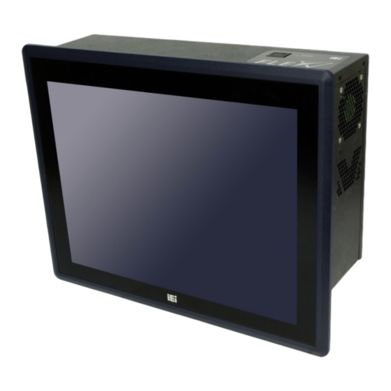
PPC-FxxC-Q370 1.1 Overview Figure 1-1: PPC-FxxC-Q370 Series Panel PC The PPC-FxxC-Q370 panel PC is powered by 8th Generation LGA1151 Intel® Core™ i7/i5/i3 and Pentium® Processor. It can be used as an inference computing system for AI applications. The PPC-FxxC-Q370 panel PC has a unique modular design to achieve high flexibility by assembling the FLEX series system with the LCD touchscreen module. -
Page 21: Model Variations
PPC-FxxC-Q370 1.2 Model Variations The model variations of the PPC-FxxC-Q370 panel PC series are listed below. Size Resolutions Processor ® ® PPC-F15C-Q370-P/PC/25 15" 1024x768 Intel Pentium Gold G5400T PPC-F15C-Q370-i3/PC/25 15" 1024x768 Intel ® Core™ i3-8100T ® PPC-F15C-Q370-i5/PC/25 15" 1024x768 Intel Core™... -
Page 22: Features
PPC-FxxC-Q370 1.3 Features The PPC-FxxC-Q370 has the following features 8th generation Intel® Core™ i7/i5/i3 and Pentium® Processor Modularized design for flexible utilization Support up to 64 GB of 2666 MHz DDR4 memory Four PCIe 3.0 slots for expansion ... -
Page 23: Bottom Panel
PPC-FxxC-Q370 1.5 Bottom Panel An overview of the bottom panel is shown in Figure 1-3. Figure 1-3: Bottom Panel NOTE: Each USB 3.2 Gen 1 port on the PPC-FxxC-Q370’s bottom panel can supply 900mA power. However, if these six USB ports are all connected to devices when booting up, the system could fail to startup due to the sudden load increase. -
Page 24: Top Panel
PPC-FxxC-Q370 1.6 Top Panel The top panel of the PPC-FxxC-Q370 has the following button and indicator: 1 x Power button with power LED indicator (power on: solid blue) 1 x HDD LED indicator (HDD activity: blinking red) Figure 1-4: Top Panel Page 6... -
Page 25: Technical Specifications
PPC-FxxC-Q370 1.7 Technical Specifications 1.7.1 15" ~ 17" Specifications PPC-F15C-Q370 PPC-FW15C-Q370 PPC-F17C-Q370 LCD Size 15" 15.6" 17" Max. Resolution 1024 x 768 1366 x 768 1280 x 1024 Brightness (cd/m²) Contrast Ratio 800:1 500:1 1000:1 LCD Color 16.2M 16.2M 16.7M Pixel Pitch (mm) 0.29 x 0.29 0.252 x 0.252... -
Page 26: Table 1-2: Technical Specifications (15" ~ 17")
PPC-FxxC-Q370 Realtek ALC662 HD codec Audio 1 x Line out 1 x Mic in Display Output 1 x HDMI 1 x HDD LED Buttons and 1 x Power button with LED indicator Indicators 1 x Reset button 1 x AT/ATX mode switch AC input ATX power supply 1. -
Page 27: 23.8" Specifications
PPC-FxxC-Q370 1.7.2 18.5" ~ 23.8" Specifications PPC-FW19C-Q370 PPC-FW22C-Q370 PPC-FW24C-Q370 LCD Size 18.5" 21.5" 23.8" Max. Resolution 1366 x 768 1920 x 1080 1920 x 1080 Brightness (cd/m²) Contrast Ratio 1000:1 1000:1 3000:1 LCD Color 16.7M 16.7M 16.7M Pixel Pitch (mm) 0.3 x 0.3 0.25 x 0.25 0.274 x 0.274... -
Page 28: Table 1-3: Technical Specifications (18.5" ~ 23.8")
PPC-FxxC-Q370 1 x Line out 1 x Mic in Display Output 1 x HDMI 1 x HDD LED Buttons and 1 x Power button with LED indicator Indicators 1 x Reset button 1 x AT/ATX mode switch AC input ATX power supply 1. -
Page 29: Dimensions
PPC-FxxC-Q370 1.8 Dimensions 1.8.1 PPC-F15C-Q370 Dimensions Figure 1-5: PPC-F15C-Q370 Dimensions (Unit: mm) Page 11... -
Page 30: Ppc-Fw15C-Q370 Dimensions
PPC-FxxC-Q370 1.8.2 PPC-FW15C-Q370 Dimensions Figure 1-6: PPC-FW15C-Q370 Dimensions (Unit: mm) Page 12... -
Page 31: Ppc-F17C-Q370 Dimensions
PPC-FxxC-Q370 1.8.3 PPC-F17C-Q370 Dimensions Figure 1-7: PPC-F17C-Q370 Dimensions (Unit: mm) Page 13... -
Page 32: Ppc-Fw19C-Q370 Dimensions
PPC-FxxC-Q370 1.8.4 PPC-FW19C-Q370 Dimensions Figure 1-8: PPC-FW19C-Q370 Dimensions (Unit: mm) Page 14... -
Page 33: Ppc-Fw22C-Q370 Dimensions
PPC-FxxC-Q370 1.8.5 PPC-FW22C-Q370 Dimensions Figure 1-9: PPC-FW22C-Q370 Dimensions (Unit: mm) Page 15... -
Page 34: Ppc-Fw24C-Q370 Dimensions
PPC-FxxC-Q370 1.8.6 PPC-FW24C-Q370 Dimensions Figure 1-10: PPC-FW24C-Q370 Dimensions (Unit: mm) Page 16... -
Page 35: Unpacking
PPC-FxxC-Q370 Chapter Unpacking Page 17... -
Page 36: Unpacking
PPC-FxxC-Q370 2.1 Unpacking To unpack the panel PC, follow the steps below: Step 1: Use box cutters, a knife or a sharp pair of scissors that seals the top side of the external (second) box. Step 2: Open the external (second) box. Step 3: Use box cutters, a knife or a sharp pair of scissors that seals the top side of the internal (first) box. -
Page 37: Optional Items
PPC-FxxC-Q370 Power cord Keys for locking HDD cover Screws (M3*4) for HDD installation Table 2-1: Package List 2.3 Optional Items The following items are optional accessories for the PPC-FxxC-Q370: PPC-F15C PPC-FW15C PPC-F17C FPK-12-R10 FPK-14-R10 FPK-13-R10 Panel mount kit PPC-FW19C PPC-FW22C PPC-FW24C FPK-13-R10 FPK-13-R10... -
Page 38: Installation
PPC-FxxC-Q370 Chapter Installation Page 20... -
Page 39: Anti-Static Precautions
PPC-FxxC-Q370 3.1 Anti-static Precautions WARNING: Failure to take ESD precautions during the maintenance of the PPC-FxxC-Q370 may result in permanent damage to the PPC-FxxC-Q370 and severe injury to the user. Electrostatic discharge (ESD) can cause serious damage to electronic components, including the WAFER series motherboard and the power module. -
Page 40: Installation Procedure
PPC-FxxC-Q370 may only be carried out by qualified personnel who are familiar with the associated dangers. Air Circulation: Make sure there is sufficient air circulation when installing the PPC-FxxC-Q370. The PPC-FxxC-Q370’s cooling vents must not be obstructed by any objects. Blocking the vents can cause overheating of the PPC-FxxC-Q370. -
Page 41: Solid-State Drive Installation
PPC-FxxC-Q370 3.4 Solid-State Drive Installation Four 2.5” SATA drives can be installed in the PPC-FxxC-Q370. The SATA drives are installed into the removable hard drive trays protected by a lockable cover on the bottom panel. To install the SSD into the system, please follow the steps below. Step 1: Unlock the HDD cover on the bottom panel with the key came with the system. -
Page 42: Figure 3-3: Ssd Retention Screws
PPC-FxxC-Q370 Step 3: Place an SSD onto the drive tray and secure the SSD with the bracket by inserting four retention screws (M3*4) into the bottom of the SSD (Figure 3-3). Figure 3-3: SSD Retention Screws Step 4: Carefully insert the SSD into the slot. Make sure the SATA connector on the SSD is securely connected to the SATA connector inside the chassis. -
Page 43: Removing The Rear Cover
PPC-FxxC-Q370 NOTE: To temporarily close the HDD cover, turn the lock knob 90° counterclockwise by hand to secure the cover. 3.5 Removing the Rear Cover WARNING: Before any internal installation procedures are carried out on the system, make sure the system is turned off and cooled down for 5 minutes. -
Page 44: Figure 3-5: Rear Cover Retention Screw Removal
PPC-FxxC-Q370 Figure 3-5: Rear Cover Retention Screw Removal Step 2: Slide the rear cover towards the I/O panel until it is disengaged from the locking mechanism. Then, lift the rear cover off the chassis. See Figure 3-6. Figure 3-6: Remove the Rear Cover Page 26... -
Page 45: Dimm Installation
PPC-FxxC-Q370 3.6 DIMM Installation To install a DIMM, please follow the steps below and refer to Figure 3-7. Figure 3-7: DIMM Installation Step 1: Remove the rear cover. See Section 3.5 above. Step 2: Locate the DIMM slots as shown in Figure 3-8. Figure 3-8: DIMM Slot Locations Step 3: Open the two handles outwards as far as they can. -
Page 46: Ssd Installation (Optional)
PPC-FxxC-Q370 Step 5: Once aligned, press down until the DIMM is properly seated. Clip the two handles into place. See Figure 3-7. Step 6: To remove a DIMM, push both handles outward. The memory module is ejected by a mechanism in the socket.Step 0: CAUTION: For dual channel configuration, install two identical memory modules... -
Page 47: Figure 3-10: Removing The M.2 Module Retention Screw
PPC-FxxC-Q370 Figure 3-10: Removing the M.2 Module Retention Screw Step 4: Line up the notch on the module with the notch on the slot. Slide the M.2 module into the socket at an angle of about 20º (Figure 3-11). Figure 3-11: Inserting the M.2 Module into the Slot at an Angle Step 5: Push the M.2 module down and secure it with the previously removed retention screw (Figure 3-12). -
Page 48: Expansion Card Installation (Optional)
PPC-FxxC-Q370 Figure 3-12: Securing the M.2 Module Step 6: Re-install the rear cover and secure it with the six retention screws previously removed. 3.8 Expansion Card Installation (Optional) The PPC-FxxC-Q370 supports multiple PCIe slots which are compatible with standard low-profile add-on cards, including two PCIe 3.0 x16 (x8 mode) and two PCIe 3.0 x4 slots. To install an expansion card, follow the steps below. -
Page 49: Figure 3-13: Pcie Slot Locations
PPC-FxxC-Q370 Figure 3-13: PCIe Slot Locations Step 3: Remove the blank bracket panel on the bottom of the PPC-FxxC-Q370 that aligns with the empty PCIe slot. Save this bracket screw. Figure 3-14: Blank Bracket Screw Removal Page 31... -
Page 50: Mounting The System
PPC-FxxC-Q370 Step 4: Align the expansion card to a PCIe slot. Press down gently, but firmly, to seat the expansion card correctly in the slot. Step 5: Install the bracket screw to secure the expansion card to the system chassis. Figure 3-15: Install and Secure Expansion Card Step 6: Re-install the rear cover and secure it with the six retention screws previously... -
Page 51: Figure 3-16: Ppc-F15C-Q370 Panel Cutout Dimensions
PPC-FxxC-Q370 Figure 3-16: PPC-F15C-Q370 Panel Cutout Dimensions Figure 3-17: PPC-FW15C-Q370 Panel Cutout Dimensions Figure 3-18: PPC-F17C-Q370 Panel Cutout Dimensions Page 33... -
Page 52: Figure 3-19: Ppc-Fw19C-Q370 Panel Cutout Dimensions
PPC-FxxC-Q370 Figure 3-19: PPC-FW19C-Q370 Panel Cutout Dimensions Figure 3-20: PPC-FW22C-Q370 Panel Cutout Dimensions Figure 3-21: PPC-FW24C-Q370 Panel Cutout Dimensions Step 3: Slide the PPC-FxxC-Q370 through the hole until the aluminum frame is flush against the panel. Page 34... -
Page 53: Rack And Cabinet Installation
PPC-FxxC-Q370 Step 4: Insert the mounting clamps into the mounting brackets and pre-formed holes along the edges of the front panel, behind the frame (Figure 3-22). The required number of mounting clamps may vary by models. Step 5: Tighten the screws that pass through the mounting clamps until the plastic caps at the front of all the screws are firmly secured to the panel (Figure 3-22). -
Page 54: Figure 3-23: The Rack/Cabinet Bracket
PPC-FxxC-Q370 Step 1: Slide the rear of the PPC-FxxC-Q370 panel PC through the rack/cabinet bracket until the aluminum frame is flush against the front of the bracket (Figure 3-23). Figure 3-23: The Rack/Cabinet Bracket Step 2: Insert the mounting clamps into the mounting brackets and pre-formed holes along the edges of the front panel, behind the frame (Figure 3-24). -
Page 55: Figure 3-25: Install Into A Rack/Cabinet
PPC-FxxC-Q370 Step 4: Slide the PPC-FxxC-Q370 with the attached rack/cabinet bracket into a rack or cabinet (Figure 3-25). Figure 3-25: Install into a Rack/Cabinet Step 5: Once the panel PC with the attached rack/cabinet bracket has been properly inserted into the rack or cabinet, secure the front of the rack/cabinet bracket to the front of the rack or cabinet (Figure 3-25).Step 0: Page 37... -
Page 56: Com Port Connection
PPC-FxxC-Q370 3.10 COM Port Connection The PPC-FxxC-Q370 has two DB-9 connectors for RS-232 serial port connection. The pinouts for the RS-232 connectors (COM1and COM2) are listed in the figure and table below. Figure 3-26: RS-232 Connector (COM1, COM2) PIN NO. DESCRIPTION Table 3-1: RS-232 Connector Pinouts Page 38... -
Page 57: Power-On Procedure
PPC-FxxC-Q370 3.11 Power-On Procedure 3.11.1 Installation Checklist WARNING: Make sure a power supply with the correct input voltage is being fed into the system. Incorrect voltages applied to the system may cause damage to the internal electronic components and may also cause injury to the user. To power on the panel PC please make sure of the following: Memory modules are installed ... -
Page 58: Software Installation
PPC-FxxC-Q370 3.12 Software Installation All the drivers for the PPC-FxxC-Q370 are available on IEI Resource Download Center (https://download.ieiworld.com). Type PPC-FxxC-Q370 and press Enter to find all the relevant software, utilities, and documentation. Figure 3-28: IEI Resource Download Center 3.12.1 Driver Download To download drivers from IEI Resource Download Center, follow the steps below. - Page 59 PPC-FxxC-Q370 Step 3: Click the driver file name on the page and you will be prompted with the following window. You can download the entire ISO file ( ), or click the small arrow to find an individual driver and click the file name to download ( ...
-
Page 60: Raid Configuration
PPC-FxxC-Q370 3.13 RAID Configuration The PPC-FxxC-Q370 can provide data protection for serial ATA (SATA) disks via the ® Intel® Rapid Storage Technology. To access the Intel Rapid Storage Technology, please follow the steps below. WARNING! Irrecoverable data loss occurs if a working drive is removed when trying to remove a failed drive. -
Page 61: Figure 3-29: Raid Configuration-Bios Setting
PPC-FxxC-Q370 Figure 3-29: RAID Configuration–BIOS Setting Step 3: Save and Exit BIOS. After the SATA support option is enabled, save and exit the BIOS. Step 4: Reboot the system. Reboot the system after saving and exiting the BIOS. Step 5: Press Ctrl+I. - Page 62 PPC-FxxC-Q370 Step 6: Configure the RAID settings. Use the Intel® Rapid Storage Technology to configure the RAID array. A) Select the option to Create RAID Volume from the Main Menu and press Enter. Intel(R) Rapid Storage Technology – Option ROM – 15.2.0.2748 Copyright (C) Intel Corporation.
-
Page 63: Bios
PPC-FxxC-Q370 Chapter BIOS Page 45... -
Page 64: Introduction
PPC-FxxC-Q370 4.1 Introduction The BIOS is programmed onto the BIOS chip. The BIOS setup program allows changes to certain system settings. This chapter outlines the options that can be changed. NOTE: Some of the BIOS options may vary throughout the life cycle of the product and are subject to change without prior notice. -
Page 65: Getting Help
PPC-FxxC-Q370 Function Decrease the numeric value or make changes Page up Move to the next page Page down Move to the previous page Main Menu – Quit and do not save changes into CMOS Status Page Setup Menu and Option Page Setup Menu -- Exit current page and return to Main Menu F1 key General help, only for Status Page Setup Menu and Option... -
Page 66: Main
PPC-FxxC-Q370 4.2 Main The Main BIOS menu (BIOS Menu 1) appears when the BIOS Setup program is entered. The Main menu gives an overview of the basic system information. Aptio Setup Utility – Copyright (C) 2018 American Megatrends, Inc. Main Advanced Chipset Security... -
Page 67: Advanced
PPC-FxxC-Q370 The Main menu has two user configurable fields: System Date [xx/xx/xx] Use the System Date option to set the system date. Manually enter the day, month and year. System Time [xx:xx:xx] Use the System Time option to set the system time. Manually enter the hours, minutes and seconds. - Page 68 PPC-FxxC-Q370 Aptio Setup Utility – Copyright (C) 2018 American Megatrends, Inc. Main Advanced Chipset Security Boot Save & Exit > CPU Configuration System ACPI Parameters > Thunderbolt(TM)Configuration > Trusted Computing > ACPI Settings > iWDD H/M Monitor ---------------------- > F81866 Super IO Configuration >...
-
Page 69: Cpu Configuration
PPC-FxxC-Q370 4.3.1 CPU Configuration Use the CPU Configuration menu (BIOS Menu 3) to view detailed CPU specifications or enable the Intel Virtualization Technology. Aptio Setup Utility – Copyright (C) 2018 American Megatrends, Inc. Advanced CPU Configuration When enabled, a VMM can utilize the additional Type Intel(R) Core(TM) CPU... - Page 70 PPC-FxxC-Q370 Active Processor Cores [All] Use the Active Processor Cores BIOS option to enable numbers of cores in the processor package. Enable all cores in the processor package. EFAULT Enable one core in the processor package. Enable two cores in the processor package.
-
Page 71: Thunderbolt Configuration
PPC-FxxC-Q370 4.3.2 Thunderbolt Configuration Use the Thunderbolt Configuration menu (BIOS Menu 4) to enable or disable the support of Thunderbolt™. Aptio Setup Utility – Copyright (C) 2018 American Megatrends, Inc. Advanced Discrete Thunderbolt(TM) Support [Disabled] Enables or Disables Discrete Thunderbolt(TM) Support. -
Page 72: Trusted Computing
PPC-FxxC-Q370 4.3.3 Trusted Computing Use the Trusted Computing menu (BIOS Menu 5) to configure settings related to the Trusted Computing Group (TCG) Trusted Platform Module (TPM). Aptio Setup Utility – Copyright (C) 2018 American Megatrends, Inc. Advanced Configuration Enables or Disables BIOS Security Device Support [Disable] support for security... -
Page 73: Acpi Settings
PPC-FxxC-Q370 4.3.4 ACPI Settings The ACPI Settings menu (BIOS Menu 6) configures the Advanced Configuration and Power Interface (ACPI) options. Aptio Setup Utility – Copyright (C) 2018 American Megatrends, Inc. Advanced ACPI Settings Select ACPI sleep state the system will enter ACPI Sleep State [S3(Suspend to RAM)] when the SUSPEND button... -
Page 74: Iwdd H/W Monitor
PPC-FxxC-Q370 4.3.5 iWDD H/W Monitor The iWDD H/W Monitor menu (BIOS Menu 7) contains the fan configuration submenu, and displays the system temperature and CPU fan speed. Aptio Setup Utility – Copyright (C) 2018 American Megatrends, Inc. Advanced PC Health Status Smart Fan Mode Select CPU temperature :+35 °C... -
Page 75: Smart Fan Mode Configuration
PPC-FxxC-Q370 CPU_CORE +12V +5VSB +3.3V +3.3VSB 4.3.5.1 Smart Fan Mode Configuration Use the Smart Fan Mode Configuration submenu (BIOS Menu 8) to configure the CPU/system fan temperature and speed settings. Aptio Setup Utility – Copyright (C) 2018 American Megatrends, Inc. Advanced Smart Fan Mode Configuration Smart Fan Mode Select... - Page 76 PPC-FxxC-Q370 CPU_FAN1 Smart Fan Control/SYS_FAN Smart Fan Control [Auto Mode] Use the CPU_FAN1 Smart Fan Control/SYS_FAN Smart Fan Control option to configure the CPU/System Smart Fan. Manual Mode The fan spins at the speed set in Manual Mode settings.
-
Page 77: F81866 Super Io Configuration
PPC-FxxC-Q370 4.3.6 F81866 Super IO Configuration Use the F81866 Super IO Configuration menu (BIOS Menu 9) to set or change the configurations for the parallel ports and serial ports. Aptio Setup Utility – Copyright (C) 2018 American Megatrends, Inc. Advanced Super IO Configuration Set Parameters of Serial Port 1 (COMA) -
Page 78: Serial Port N Configuration
PPC-FxxC-Q370 4.3.6.1 Serial Port n Configuration Use the Serial Port n Configuration menu (BIOS Menu 10) to configure the serial port n. Aptio Setup Utility – Copyright (C) 2018 American Megatrends, Inc. Advanced Serial Port n Configuration Enable or Disable Serial Port (COM) Serial Port [Enabled]... -
Page 79: Rtc Wake Settings
PPC-FxxC-Q370 4.3.7 RTC Wake Settings The RTC Wake Settings menu (BIOS Menu 11) enables the system to wake at the specified time. Aptio Setup Utility – Copyright (C) 2018 American Megatrends, Inc. Advanced Wake system with Fixed Time [Disabled] Enable or disable System wake on alarm event. -
Page 80: Serial Port Console Redirection
PPC-FxxC-Q370 Wake up minute Wake up second After setting the alarm, the computer turns itself on from a suspend state when the alarm goes off. 4.3.8 Serial Port Console Redirection The Serial Port Console Redirection menu (BIOS Menu 12) allows the console redirection options to be configured. - Page 81 PPC-FxxC-Q370 Console Redirection [Disabled] Use Console Redirection option to enable or disable the console redirection function. Disabled Disabled the console redirection function EFAULT Enabled Enabled the console redirection function The following options are available in the Console Redirection Settings submenu when the Console Redirection option is enabled.
- Page 82 PPC-FxxC-Q370 Parity [None] Use the Parity option to specify the parity bit that can be sent with the data bits for detecting the transmission errors. None No parity bit is sent with the data bits. EFAULT Even The parity bit is 0 if the number of ones in the data bits is even.
-
Page 83: Legacy Console Redirection Settings
PPC-FxxC-Q370 4.3.8.1 Legacy Console Redirection Settings Aptio Setup Utility – Copyright (C) 2018 American Megatrends, Inc. Advanced Legacy Serial Redirection Port [COM1] Select a COM port to display redirection of Legacy OS and Legacy OPROM Messages. --------------------- : Select Screen ↑... -
Page 84: Usb Configuration
PPC-FxxC-Q370 4.3.9 USB Configuration Use the USB Configuration menu (BIOS Menu 14) to read USB configuration information and configure the USB settings. Aptio Setup Utility – Copyright (C) 2018 American Megatrends, Inc. Advanced USB Configuration Enables Legacy USB support. AUTO option USB Controllers: disables legacy support 1 XHCI... -
Page 85: Nvme Configuration
PPC-FxxC-Q370 4.3.10 NVMe Configuration Use the NVMe Configuration (BIOS Menu 15) menu to display the NVMe controller and device information. Aptio Setup Utility – Copyright (C) 2018 American Megatrends, Inc. Advanced NVMe Configuration No NVMe Device Found --------------------- : Select Screen ↑... -
Page 86: Iei Feature
PPC-FxxC-Q370 4.3.12 IEI Feature Use the IEI Feature menu (BIOS Menu 17) to configure One Key Recovery function. Aptio Setup Utility – Copyright (C) 2018 American Megatrends, Inc. Advanced iEi Feature Auto Recovery Function Reboot and recover Auto Recovery Function [Disabled] system automatically within 10 min, when OS... -
Page 87: Chipset
PPC-FxxC-Q370 4.4 Chipset Use the Chipset menu (BIOS Menu 18) to access the PCH IO and System Agent (SA) configuration menus. WARNING! Setting the wrong values for the Chipset BIOS selections in the Chipset BIOS menu may cause the system to malfunction. Aptio Setup Utility –... -
Page 88: System Agent (Sa) Configuration
PPC-FxxC-Q370 4.4.1 System Agent (SA) Configuration Use the System Agent (SA) Configuration menu (BIOS Menu 19) to configure the System Agent (SA) parameters. Aptio Setup Utility – Copyright (C) 2018 American Megatrends, Inc. Chipset System Agent (SA) Configuration Memory Configuration Parameters VT-d Supported... -
Page 89: Memory Configuration
PPC-FxxC-Q370 4.4.1.1 Memory Configuration Use the Memory Configuration submenu (BIOS Menu 20) to view memory information. Aptio Setup Utility – Copyright (C) 2018 American Megatrends, Inc. Chipset Memory Configuration CHA_DIMM0 Populated & Enabled Size 8192 MB (DDR4) --------------------- Number of Ranks : Select Screen Manufacturer Transcend... -
Page 90: Graphics Configuration
PPC-FxxC-Q370 4.4.1.2 Graphics Configuration Use the Graphics Configuration (BIOS Menu 21) menu to configure the video device connected to the system. Aptio Setup Utility – Copyright (C) 2018 American Megatrends, Inc. Chipset Graphics Configuration Select which of IGFX/PEG/PCI Graphics Primary Display [Auto] device should be Primary Internal Graphics... - Page 91 PPC-FxxC-Q370 Internal Graphics [Enabled] Use the Internal Graphics option to configure whether to keep IGFX enabled. If user wants to support dual display by internal graphics and external graphics, this Internal Graphics option should be set to Enabled and the above Primary Display option should be set to IGFX.
-
Page 92: Peg Port Configuration
PPC-FxxC-Q370 Backlight Control Mode [LED] Use the Backlight Control Mode option to specify the backlight control mode. Configuration options are listed below. Default CCFL Backlight Control Type [PWM] Use the Backlight Control Type option to specify the backlight control type. Configuration options are listed below. - Page 93 PPC-FxxC-Q370 Enable Root Port [Enabled] Use the Enable Root Port option to enable or disable the PCI Express (PEG) controller. Disabled Disables the PCI Express (PEG) controller. Enabled Enables the PCI Express (PEG) controller. EFAULT Max Link Speed [Auto] ...
-
Page 94: Pch-Io Configuration
PPC-FxxC-Q370 Detect Non-Compliance Device [Disabled] Use the Detect Non-Compliance Device option to detect non-compliance PCIe device in PEG. Disabled Do not detect non-compliance PCIe device in PEG EFAULT Enabled Detect non-compliance PCIe device in PEG 4.4.2 PCH-IO Configuration Use the PCH-IO Configuration menu (BIOS Menu 24) to configure the PCH parameters. - Page 95 PPC-FxxC-Q370 Power Saving Function(ERP) [Disabled] Use the Power Saving Function(ERP) BIOS option to enable or disable the power saving function. Disabled Power saving function is disabled. EFAULT Enabled Power saving function is enabled. It will reduce power consumption when the system is off.
-
Page 96: Pci Express Configuration
PPC-FxxC-Q370 4.4.2.1 PCI Express Configuration Use the PCI Express Configuration menu (BIOS Menu 25) to configure the PCI Express and M.2 slots. Aptio Setup Utility – Copyright (C) 2018 American Megatrends, Inc. Chipset PCI Express Configuration Select PCIEX4_3 slot function. >... - Page 97 PPC-FxxC-Q370 4.4.2.1.1 PCIEX4_1 Slot, PCIEX4_2 Slot and M.2 Slots Aptio Setup Utility – Copyright (C) 2018 American Megatrends, Inc. Advanced PCIEX4_1 Slot [Enabled] Control the PCI Express PCIe Speed [Auto] Root Port. --------------------- : Select Screen ↑ ↓: Select Item Enter: Select +/-: Change Opt.
- Page 98 PPC-FxxC-Q370 M2_M1 Slot [Enabled] Use the M2_M1 Slot option to enable or disable the M.2 2280 M-key slot. Disabled Disables the M.2 2280 M-key slot. Enabled Enables the M.2 2280 M-key slot. EFAULT M2_M2 Slot [Enabled] Use the M2_M2 Slot option to enable or disable the M.2 2280 M-key slot.
-
Page 99: Sata Configuration
PPC-FxxC-Q370 4.4.2.2 SATA Configuration Use the SATA Configuration menu (BIOS Menu 27) to change and/or set the configuration of the SATA devices installed in the system. Aptio Setup Utility – Copyright (C) 2018 American Megatrends, Inc. Advanced SATA And RST Configuration Enable or disable SATA Device. - Page 100 PPC-FxxC-Q370 SATA Mode Selection [AHCI] Use the SATA Mode Selection option to determine how the SATA devices operate. AHCI Configures SATA devices as AHCI device. EFAULT Intel Configures SATA devices to the Intel RST Premium Premium With With Intel Optane System Acceleration mode.
-
Page 101: Hd Audio Configuration
PPC-FxxC-Q370 4.4.2.3 HD Audio Configuration Use the HD Audio Configuration menu (BIOS Menu 28) to configure the PCH Azalia settings. Aptio Setup Utility – Copyright (C) 2018 American Megatrends, Inc. Chipset HD Audio Configuration Control Detection of the HD-Audio device. HD Audio [Enabled] Disable = HDA will be... -
Page 102: Security
PPC-FxxC-Q370 4.5 Security Use the Security menu (BIOS Menu 29) to set system and user passwords. Aptio Setup Utility – Copyright (C) 2018 American Megatrends, Inc. Main Advanced Chipset Security Boot Save & Exit Password Description Set Administrator Password If ONLY the Administrator’s password is set, then this only limits access to Setup and is only asked for when entering Setup. -
Page 103: Boot
PPC-FxxC-Q370 4.6 Boot Use the Boot menu (BIOS Menu 30) to configure system boot options. Aptio Setup Utility – Copyright (C) 2018 American Megatrends, Inc. Main Advanced Chipset Security Boot Save & Exit Boot Configuration Select the keyboard Bootup NumLock State [On] NumLock state Quiet Boot... - Page 104 PPC-FxxC-Q370 Quiet Boot [Enabled] Use the Quiet Boot BIOS option to select the screen display when the system boots. Disabled Normal POST messages displayed Enabled OEM Logo displayed instead of POST messages EFAULT UEFI Boot [Disabled] Use the UEFI Boot option to enable or disable to boot from the UEFI devices.
-
Page 105: Save & Exit
PPC-FxxC-Q370 4.7 Save & Exit Use the Safe & Exit menu (BIOS Menu 31) to load default BIOS values, optimal failsafe values and to save configuration changes. Aptio Setup Utility – Copyright (C) 2018 American Megatrends, Inc. Main Advanced Chipset Security Boot Save &... -
Page 106: Troubleshooting And Maintenance
PPC-FxxC-Q370 Chapter Troubleshooting and Maintenance Page 88... -
Page 107: C-Q370 System Maintenance Overview
PPC-FxxC-Q370 WARNING: Take Anti-Static precautions whenever maintenance is being carried out on the system components. Failure to take anti-static precautions can cause permanent system damage. For more details on anti-static precautions, please refer to Section 3.1. 5.1 PPC-FxxC-Q370 System Maintenance Overview NOTE: When doing maintenance operations on the system, please follow the instructions in this chapter. -
Page 108: The System Doesn't Boot Up
PPC-FxxC-Q370 Step 4: Plug the system into a monitor and check to see if anything appears on the screen. If the boot-up screen appears it means the power LED has failed. To fix Step 0: this problem, contact an IEI sales representative directly. 5.2.2 The System Doesn’t Boot Up If the system doesn’t boot up please do the following: Step 1:... -
Page 109: Component Replacement
PPC-FxxC-Q370 5.3 Component Replacement WARNING! Users are not advised to attempt to repair or replace any internal or external components of the PPC-FxxC-Q370 panel PC. If any other components fail or need replacement, contact the IEI reseller or vendor you purchased the PPC-FxxC-Q370 from or contact an IEI sales representative directly. -
Page 110: Interface Connectors
PPC-FxxC-Q370 Chapter Interface Connectors Page 92... -
Page 111: Peripheral Interface Connectors
PPC-FxxC-Q370 6.1 Peripheral Interface Connectors The PPC-FxxC-Q370 panel PC motherboard comes with a number of peripheral interface connectors and configuration jumpers. The connector locations are shown in Figure 6-1 and Figure 6-2. The Pin 1 locations of the on-board connectors are also indicated in the diagrams. -
Page 112: Internal Peripheral Connectors
PPC-FxxC-Q370 6.2 Internal Peripheral Connectors Internal peripheral connectors are found on the motherboard and are only accessible when the motherboard is outside of the chassis. The table below shows a list of the peripheral interface connectors on the PPC-FxxC-Q370 motherboard. Pinouts of these connectors can be found in the following sections. -
Page 113: Atx Power Input Connector (Atx1)
PPC-FxxC-Q370 Connector Type Label SATA 6Gb/s connectors SATA connector S_ATA5, S_ATA6 SMBus connector 4-pin wafer SMB1 SPI flash connector 6-pin wafer J_SPI1 SPI flash (EC) connector 6-pin wafer J_EC1 Speaker connector 2-pin wafer SPK1 TPM connector 20-pin header TPM1 USB 2.0 connectors (single) 4-pin wafer JUSB1, JUSB2 USB 2.0 connector (dual) -
Page 114: Additional Power Connector (Atxpwr1)
PPC-FxxC-Q370 6.2.2 Additional Power Connector (ATXPWR1) PIN NO. DESCRIPTION VCC12V VCC5V Table 6-3: Additional Power Connector (ATXPWR1) Pinouts 6.2.3 Battery Connector (BAT1) PIN NO. DESCRIPTION VBATT Table 6-4: Battery Connector (BAT1) Pinouts 6.2.4 Chassis Intrusion Connector (CHASSIS1) PIN NO. DESCRIPTION VCC3V CHASSIE Table 6-5: Chassis Intrusion Connector (CHASSIS1) Pinouts... -
Page 115: Dio Connector (Dio1)
PPC-FxxC-Q370 6.2.6 DIO Connector (DIO1) PIN NO. DESCRIPTION PIN NO. DESCRIPTION Output 3 Output 2 Output 1 Output 0 Input 3 Input 2 Input 1 Input 0 Table 6-7: DIO Connector (DIO1) Pinouts 6.2.7 EC Debug Port (EC_DBG1) PIN NO. -
Page 116: Fan Connectors, System (Sys_Fan1, Sys_Fan2, Sys_Fan3)
PPC-FxxC-Q370 6.2.9 Fan Connectors, System (SYS_FAN1, SYS_FAN2, SYS_FAN3) PIN NO. DESCRIPTION +12V FANIO Table 6-10: System Fan Connectors (SYS_FAN1, SYS_FAN2, SYS_FAN3) Pinouts 6.2.10 I C Connector (I2C1) PIN NO. DESCRIPTION I2C_DATA I2C_CLK Table 6-11: I C Connector (I2C1) Pinouts 6.2.11 Internal DisplayPort Connector (IDP1) PIN NO. -
Page 117: Led Connector, Hdd (H_Led1)
PPC-FxxC-Q370 6.2.12 LED Connector, HDD (H_LED1) PIN NO. DESCRIPTION VCC5V SATA_LED# Table 6-13: HDD LED Connector (H_LED1) Pinouts 6.2.13 LED Connector, Power (P_LED1) PIN NO. DESCRIPTION VCC5V Table 6-14: Power LED Connector (P_LED1) Pinouts 6.2.14 LVDS Connector (LVDS1) PIN NO. DESCRIPTION PIN NO. -
Page 118: Lvds Backlight Connector (Inv1)
PPC-FxxC-Q370 PIN NO. DESCRIPTION PIN NO. DESCRIPTION CLK1M Table 6-15: LVDS Connector (LVDS1) Pinouts 6.2.15 LVDS Backlight Connector (INV1) PIN NO. DESCRIPTION VCC12V VCC12V Backlight ON/OFF Backlight Brightness Control Table 6-16: LVDS Backlight Connector (INV1) Pinouts 6.2.16 Mini SAS Connector (MINI_SAS1) PIN NO. -
Page 119: Power Button Connector (P_Btn1)
PPC-FxxC-Q370 PIN NO. DESCRIPTION PIN NO. DESCRIPTION SATA_TX1+ SATA_TX0+ SATA_TX1- SATA_TX0- SATA_TX3+ SATA_TX2+ SATA_TX3- SATA_TX2- Table 6-17: Mini SAS Connector (MINI_SAS1) Pinouts 6.2.17 Power Button Connector (P_BTN1) PIN NO. DESCRIPTION PWRBTN_SW# Table 6-18: Power Button Connector (P_BTN1) Pinouts 6.2.18 Touch Panel Connector (TS1) PIN NO. -
Page 120: Connector (Com2)
PPC-FxxC-Q370 6.2.19 RS-232 Connector (COM2) PIN NO. DESCRIPTION PIN NO. DESCRIPTION Table 6-20: RS-232 Connector (COM2) Pinouts 6.2.20 RS-422/485 Connector (COM3) PIN NO. DESCRIPTION PIN NO. DESCRIPTION COM3_TX- COM4_TX- ... -
Page 121: Spi Flash Connector (J_Spi1)
PPC-FxxC-Q370 6.2.22 SPI Flash Connector (J_SPI1) PIN NO. DESCRIPTION VCC3V SPI_CS SPI_SO SPI_CLK SPI_SI Table 6-23: SPI Flash Connector (J_SPI1) Pinouts 6.2.23 SPI Flash (EC) Connector (J_EC1) PIN NO. DESCRIPTION VCC3V SPI_CS#0_CN_EC SPI_SO_SW_EC SPI_CLK_SW_EC SPI_SI_SW_EC Table 6-24: SPI Flash (EC) Connector (J_EC1) Pinouts 6.2.24 Speaker Connector (SPK1) PIN NO. -
Page 122: Tpm Connector (Tpm1)
PPC-FxxC-Q370 6.2.25 TPM Connector (TPM1) PIN NO. DESCRIPTION PIN NO. DESCRIPTION CLOCK FRAME RESET VCC5V LAD3 LAD2 VCC3V LAD1 LAD0 SMB_CLK SMB_DATA ... -
Page 123: Usb 2.0 Connectors, Dual (Jusb3)
PPC-FxxC-Q370 6.2.27 USB 2.0 Connectors, Dual (JUSB3) PIN NO. DESCRIPTION PIN NO. DESCRIPTION SB5V DATA- DATA+ DATA+ DATA- SB5V Table 6-28: Dual USB 2.0 Connector (JUSB3) Pinouts 6.2.28 USB DOM Connector (USB_DOM1) PIN NO. -
Page 124: Clear Cmos Jumper (J_Cmos1)
PPC-FxxC-Q370 6.3.1 Clear CMOS Jumper (J_CMOS1) Description Open Keep current BIOS setup (Default) Short Clear BIOS Table 6-31: Clear CMOS Jumper (J_CMOS1) Settings 6.3.2 ME RTC Register Setting Jumper (ME_RTC1) Description Short 1-2 Save ME RTC registers (Default) Short 2-3 Clear ME RTC registers Table 6-32: ME RTC Register Jumper (ME_RTC1) Settings Page 106... -
Page 125: A Regulatory Compliance
PPC-FxxC-Q370 Appendix Regulatory Compliance Page 107... - Page 126 PPC-FxxC-Q370 DECLARATION OF CONFORMITY This equipment is in conformity with the following EU directives: EMC Directive (2014/30/EU) Low-Voltage Directive (2014/35/EU) RoHS II Directive (2011/65/EU, 2015/863/EU) If the user modifies and/or install other devices in the equipment, the CE conformity declaration may no longer apply.
- Page 127 PPC-FxxC-Q370 Español [Spanish] IEI Integration Corp declara que el equipo cumple con los requisitos esenciales y cualesquiera otras disposiciones aplicables o exigibles de la Directiva 2014/53/EU. Ελληνική [Greek] IEI Integration Corp ΔΗΛΩΝΕΙ ΟΤΙ ΕΞΟΠΛΙΣΜΟΣ ΣΥΜΜΟΡΦΩΝΕΤΑΙ ΠΡΟΣ ΤΙΣ ΟΥΣΙΩΔΕΙΣ ΑΠΑΙΤΗΣΕΙΣ ΚΑΙ ΤΙΣ ΛΟΙΠΕΣ ΣΧΕΤΙΚΕΣ ΔΙΑΤΑΞΕΙΣ ΤΗΣ ΟΔΗΓΙΑΣ 2014/53/EU.
- Page 128 PPC-FxxC-Q370 Româna [Romanian] IEI Integration Corp declară că acest echipament este in conformitate cu cerinţele esenţiale şi cu celelalte prevederi relevante ale Directivei 2014/53/EU. Slovensko [Slovenian] IEI Integration Corp izjavlja, da je ta opreme v skladu z bistvenimi zahtevami in ostalimi relevantnimi določili direktive 2014/53/EU.
- Page 129 PPC-FxxC-Q370 FCC WARNING This equipment complies with Part 15 of the FCC Rules. Operation is subject to the following two conditions: This device may not cause harmful interference, and This device must accept any interference received, including interference that may cause undesired operation.
-
Page 130: B Safety Precautions
PPC-FxxC-Q370 Appendix Safety Precautions Page 112... -
Page 131: Safety Precautions
PPC-FxxC-Q370 WARNING: The precautions outlined in this chapter should be strictly followed. Failure to follow these precautions may result in permanent damage to the PPC-FxxC-Q370. B.1 Safety Precautions Please follow the safety precautions outlined in the sections that follow: B.1.1 General Safety Precautions Please ensure the following safety precautions are adhered to at all times. -
Page 132: Anti-Static Precautions
PPC-FxxC-Q370 If considerable amounts of dust, water, or fluids enter the device, turn off the power supply immediately, unplug the power cord, and contact the PPC-FxxC-Q370 vendor. DO NOT: Drop the device against a hard surface. In a site where the ambient temperature exceeds the rated temperature B.1.2 Anti-static Precautions WARNING: Failure to take ESD precautions during the installation of the... -
Page 133: Product Disposal
PPC-FxxC-Q370 B.1.3 Product Disposal CAUTION: Risk of explosion if battery is replaced by an incorrect type. Only certified engineers should replace the on-board battery. Dispose of used batteries according to instructions and local regulations. Outside the European Union–If you wish to dispose of used electrical and ... -
Page 134: Maintenance And Cleaning Precautions
PPC-FxxC-Q370 B.2 Maintenance and Cleaning Precautions When maintaining or cleaning the PPC-FxxC-Q370, please follow the guidelines below. WARNING: For safety reasons, turn-off the power and unplug the panel PC before cleaning. If you dropped any material or liquid such as water onto the panel ... - Page 135 PPC-FxxC-Q370 Water or rubbing alcohol–A cloth moistened with water or rubbing alcohol can be used to clean the device. Using solvents–The use of solvents is not recommended when cleaning the device as they may damage the plastic parts. Vacuum cleaner–Using a vacuum specifically designed for computers is one ...
-
Page 136: Cbios Menu Options
PPC-FxxC-Q370 Appendix BIOS Menu Options Page 118... -
Page 137: Bios Configuration Options
PPC-FxxC-Q370 C.1 BIOS Configuration Options Below is a list of BIOS configuration options described in Chapter 4. System Date [xx/xx/xx] ......................49 System Time [xx:xx:xx] ....................... 49 Intel (VMX) Virtualization Technology [Disabled] ............. 51 Active Processor Cores [All] ....................52 Intel(R) SpeedStep(tm) [Enabled] .................. - Page 138 PPC-FxxC-Q370 DVMT Total Gfx Mem [MAX] ....................73 Primary IGFX Boot Display [VBIOS Default] ..............73 Backlight Control Mode [LED] .................... 74 Backlight Control Type [PWM] ................... 74 Enable Root Port [Enabled] ....................75 Max Link Speed [Auto] ......................75 Detect Non-Compliance Device [Disabled] ...............
-
Page 139: D Watchdog Timer
PPC-FxxC-Q370 Appendix Watchdog Timer Page 121... - Page 140 PPC-FxxC-Q370 NOTE: The following discussion applies to DOS environment. IEI support is contacted or the IEI website visited for specific drivers for more sophisticated operating systems, e.g., Windows and Linux. The Watchdog Timer is provided to ensure that standalone systems can always recover from catastrophic conditions that cause the CPU to crash.
- Page 141 PPC-FxxC-Q370 NOTE: When exiting a program it is necessary to disable the Watchdog Timer, otherwise the system resets. Example program: ; INITIAL TIMER PERIOD COUNTER W_LOOP: AX, 6F02H ;setting the time-out value BL, 30 ;time-out value is 48 seconds ; ADD THE APPLICATION PROGRAM HERE EXIT_AP, 1 ;is the application over? W_LOOP...
-
Page 142: E Error Beep Code
PPC-FxxC-Q370 Appendix Error Beep Code Page 124... -
Page 143: Pei Beep Codes
PPC-FxxC-Q370 E.1 PEI Beep Codes Number of Beeps Description Memory not Installed Memory was installed twice (InstallPeiMemory routine in PEI Core called twice) Recovery started DXEIPL was not found DXE Core Firmware Volume was not found Recovery failed S3 Resume failed Reset PPI is not available E.2 DXE Beep Codes Number of Beeps... -
Page 144: F Hazardous Materials Disclosure
PPC-FxxC-Q370 Appendix Hazardous Materials Disclosure Page 126... -
Page 145: Rohs Ii Directive (2015/863/Eu)
PPC-FxxC-Q370 F.1 RoHS II Directive (2015/863/EU) The details provided in this appendix are to ensure that the product is compliant with the RoHS II Directive (2015/863/EU). The table below acknowledges the presences of small quantities of certain substances in the product, and is applicable to RoHS II Directive (2015/863/EU). -
Page 146: China Rohs
PPC-FxxC-Q370 F.2 China RoHS 此附件旨在确保本产品符合中国 RoHS 标准。以下表格标示此产品中某有毒物质的含量符 合中国 RoHS 标准规定的限量要求。 本产品上会附有”环境友好使用期限”的标签,此期限是估算这些物质”不会有泄漏或突变”的 年限。本产品可能包含有较短的环境友好使用期限的可替换元件,像是电池或灯管,这些 元件将会单独标示出来。 部件名称 有毒有害物质或元素 壳体 印刷电路板 金属螺帽 电缆组装 风扇组装 电力供应组装 电池 O: 表示该有毒有害物质在该部件所有物质材料中的含量均在 SJ/T11364-2014 與 GB/T26572-2011 标准规定的限量要求以下。 X: 表示该有毒有害物质至少在该部件的某一均质材料中的含量超出 SJ/T11364-2014 與 GB/T26572-2011 标准规定的限量要求。 Page 128...
Need help?
Do you have a question about the PPC-F C-Q370 Series and is the answer not in the manual?
Questions and answers