Table of Contents
Advertisement
Quick Links
Advertisement
Chapters
Table of Contents

Related Manuals for IEI Technology PPC-37 A-N26 Series


Summary of Contents for IEI Technology PPC-37 A-N26 Series
- Page 1 PPC-37xxA-N26 Panel PC PPC-37xxA-N26 Panel PC MODEL: PPC-37xxA-N26 Panel PC with Intel® Atom™ N2600 CPU, DDR3, Touchscreen, USB 3.0, Dual GbE, HDMI, VGA, mSATA, SATA 3Gb/s, Audio, RS-232/422/485, IP 65 Compliant Front Panel and RoHS Compliant User Manual Page i Rev.
- Page 2 PPC-37xxA-N26 Panel PC Revision Date Version Changes 12 March, 2014 1.10 Updated for R11 version Updated Section 6.8: Touchscreen Driver Installation Added touchscreen type selection jumper in Section 3.6.2 24 December, 2012 1.00 Initial release Page ii...
- Page 3 PPC-37xxA-N26 Panel PC Copyright COPYRIGHT NOTICE The information in this document is subject to change without prior notice in order to improve reliability, design and function and does not represent a commitment on the part of the manufacturer. In no event will the manufacturer be liable for direct, indirect, special, incidental, or consequential damages arising out of the use or inability to use the product or documentation, even if advised of the possibility of such damages.
-
Page 4: Table Of Contents
PPC-37xxA-N26 Panel PC Table of Contents 1 INTRODUCTION......................1 1.1 O ........................2 VERVIEW 1.2 M ....................3 ODEL ARIATIONS 1.3 F ........................3 EATURES 1.4 E ....................4 XTERNAL VERVIEW 1.4.1 Front Panel ......................4 1.4.2 Rear Panel ......................4 1.4.3 Bottom Panel...................... - Page 5 PPC-37xxA-N26 Panel PC 3.6.4 Clear CMOS Jumper..................25 3.6.5 mSATA/PCIe Mini Mode Selection ..............26 SATA SSD I ..................26 NSTALLATION 3.8 HDD I ....................28 NSTALLATION 3.8.1 PPC-3708A-N26 HDD Installation ..............28 3.8.2 PPC-3710A-N26 HDD Installation ..............31 3.8.3 PPC-3712A-N26 HDD Installation ..............32 3.9 O (PPC-3712A-N26 O ).......
- Page 6 PPC-37xxA-N26 Panel PC 5.1 I ......................61 NTRODUCTION 5.1.1 Starting Setup....................61 5.1.2 Using Setup ...................... 61 5.1.3 Getting Help..................... 62 5.1.4 Unable to Reboot after Configuration Changes ..........62 5.1.5 BIOS Menu Bar....................62 5.2 M ........................63 5.3 A .......................
- Page 7 PPC-37xxA-N26 Panel PC 6.7 USB 3.0 D ................104 RIVER NSTALLATION 6.7.1 Installing USB 3.0 Driver during Windows® 7 OS Installation....107 6.8 T ..............111 OUCHSCREEN RIVER NSTALLATION 6.8.1 Calibrating the Touchscreen ................114 7 INTERFACE CONNECTORS ..................117 7.1 P ..............118 ERIPHERAL NTERFACE ONNECTORS...
- Page 8 PPC-37xxA-N26 Panel PC B.1.1 System Requirement..................134 B.1.2 Supported Operating System ................. 135 B.2 S ................ 136 ETUP ROCEDURE FOR INDOWS B.2.1 Hardware and BIOS Setup ................137 B.2.2 Create Partitions ................... 137 B.2.3 Install Operating System, Drivers and Applications ........141 B.2.4 Building the Recovery Partition ..............
- Page 9 PPC-37xxA-N26 Panel PC E HAZARDOUS MATERIALS DISCLOSURE ............181 E.1 H IPB P AZARDOUS ATERIAL ISCLOSURE ABLE FOR RODUCTS ERTIFIED AS HS C 2002/95/EC W ........182 OMPLIANT NDER ITHOUT ERCURY Page ix...
- Page 10 PPC-37xxA-N26 Panel PC List of Figures Figure 1-1: PPC-37xxA-N26 Panel PC...................2 Figure 1-2: Front View ........................4 Figure 1-3: Rear View ........................5 Figure 1-4: Bottom View ........................6 Figure 1-5: PPC-3712A-N26 Left View ..................6 Figure 1-6: PPC-3710A-N26 Frame Rear View ................7 Figure 1-7: PPC-3712A-N26 Frame Rear View ................7 Figure 1-8: PPC-3708A-N26 Dimensions (mm)................8 Figure 1-9: PPC-3710A-N26 Dimensions (mm)................9 Figure 1-10: PPC-3712A-N26 Dimensions (mm)................10...
- Page 11 PPC-37xxA-N26 Panel PC Figure 3-22: Optical Drive SATA Cable ..................35 Figure 3-23: Replacing the Optical Drive Bracket ..............35 Figure 3-24: Wall-mounting Bracket ...................37 Figure 3-25: Mount the Chassis ....................38 Figure 3-26: Secure the Chassis ....................39 Figure 3-27: PPC-3708A-N26 Panel Cutout Dimensions ............40 Figure 3-28: PPC-3710A-N26 Panel Cutout Dimensions ............40 Figure 3-29: Tighten the Panel Mounting Clamp Screws ............41 Figure 3-30: Panel Mounting Kit....................41...
- Page 12 PPC-37xxA-N26 Panel PC Figure 6-9: VGA Driver License Agreement................98 Figure 6-10: VGA Driver Read Me File ..................98 Figure 6-11: VGA Driver Setup Operations................99 Figure 6-12: VGA Driver Installation Finish Screen ..............99 Figure 6-13: LAN Driver Welcome Screen ................100 Figure 6-14: LAN Driver Installation ..................101 Figure 6-15: LAN Driver Installation Complete...............
- Page 13 PPC-37xxA-N26 Panel PC Figure B-4: Command Prompt ....................139 Figure B-5: Partition Creation Commands................140 Figure B-6: Launching the Recovery Tool ................142 Figure B-7: Manual Recovery Environment for Windows ............. 142 Figure B-8: Building the Recovery Partition................143 Figure B-9: Press Any Key to Continue .................. 143 Figure B-10: Press F3 to Boot into Recovery Mode...............
- Page 14 PPC-37xxA-N26 Panel PC Figure B-39: Restore System Backup Complete Window ............. 161 Figure B-40: Symantec Ghost Window ................... 161 Page xiv...
- Page 15 PPC-37xxA-N26 Panel PC List of Tables Table 1-1: Model Variations ......................3 Table 1-2: System Specifications....................12 Table 2-1: Packing List.........................16 Table 2-2: Optional Items......................17 Table 3-1: Jumpers ........................23 Table 3-2: Preconfigured Jumpers .....................23 Table 3-3: LVDS Voltage Selection Jumper Settings..............23 Table 3-4: Touchscreen Type Selection Jumper Settings............24 Table 3-5: AT/ATX Power Selection Jumper Settings...............24 Table 3-6: Clear CMOS Jumper Settings..................25 Table 3-7: mSATA/PCIe Mini Mode Selection Jumper Settings..........26...
- Page 16 PPC-37xxA-N26 Panel PC Table 7-18: Rear Panel Connectors ..................126 Table 7-19: HDMI Connector (HDMI1) Pinouts................ 126 Table 7-20: RJ-45 LAN Connector Pinouts ................127 Table 7-21: USB 2.0 Connectors (USB_CON2) Pinouts............127 Table 7-22: USB 3.0 Connectors (USB_CON1) Pinouts............127 Table 7-23: VGA Connector (VGA1) Pinouts ................
-
Page 17: Introduction
PPC-37xxA-N26 Panel PC Chapter Introduction Page 1... -
Page 18: Overview
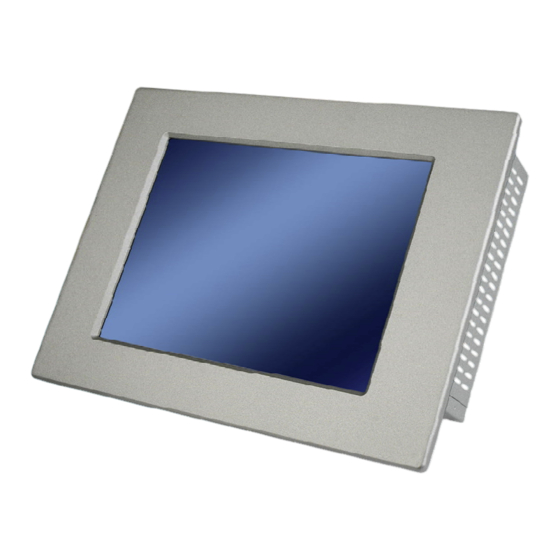
PPC-37xxA-N26 Panel PC 1.1 Overview Figure 1-1: PPC-37xxA-N26 Panel PC The PPC-37xxA-N26 is an industrial flat panel PC. The PPC-37xxA-N26 can be used for machine control, production lines, kiosks and information stations. The PPC-37xxA-N26 is preinstalled with an Intel® Atom™ N2600 CPU for applications where more computing power is needed. -
Page 19: Model Variations
PPC-37xxA-N26 Panel PC 1.2 Model Variations The model numbers and model variations are listed below. Model Memory Screen PPC-3708A-N26/R/2G-R11 1.6 GHz Intel® Atom™ N2600 2 GB DDR3 8.4” PPC-3710A-N26/R/2G-R11 1.6 GHz Intel® Atom™ N2600 2 GB DDR3 10.4” PPC-3712A-N26/R/2G-R11 1.6 GHz Intel® Atom™ N2600 2 GB DDR3 12.1”... -
Page 20: External Overview
PPC-37xxA-N26 Panel PC 1.4 External Overview The PPC-37xxA-N26 panel PC is comprised of an LCD screen, aluminum front panel and heavy duty steel rear and side panels. The rear panel provides screw holes for wall and an arm mounting. The bottom panel provides access to external interface connectors that include GbE, USB 3.0, USB 2.0, audio, serial port connectors, VGA port and HDMI port. -
Page 21: Bottom Panel
PPC-37xxA-N26 Panel PC Figure 1-3: Rear View 1.4.3 Bottom Panel The bottom panel has the following interfaces: 1 x 12 V DC power input connector 1 x Power switch 2 x USB 3.0 connectors 2 x USB 2.0 connectors 2 x RJ-45 GbE connectors 2 x RS-232 connectors 1 x RS-422/485 connector 1 x Line-out jack... -
Page 22: Side Panels
PPC-37xxA-N26 Panel PC Figure 1-4: Bottom View 1.4.4 Side Panels The both sides panel of the panel PC contain some vents for ventilation. The left side panel of PPC-3712A-N26 provides access to the slim type optical disk drive bay. Figure 1-5: PPC-3712A-N26 Left View Page 6... -
Page 23: Frame
PPC-37xxA-N26 Panel PC 1.4.5 Frame An aluminum frame surrounds the LCD screen. The aluminum frames of the PPC-3710A-N26 and PPC-3712A-N26 have small screw holes that are used when the flat panel PC is mounted into a rack or cabinet. These screws are circled in Figure 1-7 and Figure 1-7. -
Page 24: Dimensions
PPC-37xxA-N26 Panel PC 1.5 Dimensions 1.5.1 PPC-3708A-N26 Dimensions Figure 1-8: PPC-3708A-N26 Dimensions (mm) Page 8... -
Page 25: Ppc-3710A-N26 Dimensions
PPC-37xxA-N26 Panel PC 1.5.2 PPC-3710A-N26 Dimensions Figure 1-9: PPC-3710A-N26 Dimensions (mm) Page 9... -
Page 26: Ppc-3712A-N26 Dimensions
PPC-37xxA-N26 Panel PC 1.5.3 PPC-3712A-N26 Dimensions Figure 1-10: PPC-3712A-N26 Dimensions (mm) Page 10... -
Page 27: Specifications
PPC-37xxA-N26 Panel PC 1.6 Specifications The technical specifications for the PPC-37xxA-N26 system are listed in Table 1-2. PPC-3708A-N26 PPC-3710A-N26 PPC-3712A-N26 8.4” 10.4” 12.1” LCD Size 800 (W) x 600 (H) 800 (W) x 600 (H) 1024 (W) x 768 (H) Max. -
Page 28: Table 1-2: System Specifications
PPC-37xxA-N26 Panel PC PPC-3708A-N26 PPC-3710A-N26 PPC-3712A-N26 9 V ~ 28 V DC Power Requirement P/N: 63040-010060-050-RS 60 W Power Adapter Input: 90 V AC ~ 264 V AC, 50/60 Hz Output: 12 V DC 2 x USB 3.0 2 x USB 2.0 2 x RS-232 1 x RS-422/485 1 x HDMI connector... -
Page 29: Unpacking
PPC-37xxA-N26 Panel PC Chapter Unpacking Page 13... -
Page 30: Unpacking
PPC-37xxA-N26 Panel PC 2.1 Unpacking To unpack the panel PC, follow the steps below: WARNING! The front side LCD screen has a protective plastic cover stuck to the screen. Only remove the plastic cover after the panel PC has been properly installed. -
Page 31: Packing List
PPC-37xxA-N26 Panel PC 2.2 Packing List The PPC-37xxA-N26 panel PC is shipped with the following components: Quantity Item Image PPC-37xxA-N26 Power adapter (P/N: 63040-010060-050-RS) Power cord (P/N: 32702-000200-100-RS) Screw kit (P/N: 19600-000205-RS) Touch pen (P/N: 43125-0002C0-00-RS) Panel mounting kit (P/N: 19Z00-000026-RS) Wall mounting kit (P/N: 41020-016102-00-RS, 41014-057602-00-RS) -
Page 32: Optional Items
PPC-37xxA-N26 Panel PC Quantity Item Image One Key Recovery CD Table 2-1: Packing List If any of the above items are missing or damaged, contact the distributor or sales representative immediately. 2.3 Optional Items The following items are optional accessories for the PPC-37xxA-N26: Item Image Slim type SATA DVD-ROM (PPC-3712A-N26 only) -
Page 33: Table 2-2: Optional Items
PPC-37xxA-N26 Panel PC Item Image Wi-Fi module with RF cable and antenna, 2T2R, 802.11b/g/n (P/N: PPC-WL-KIT02-R10) Table 2-2: Optional Items Page 17... -
Page 34: Installation
PPC-37xxA-N26 Panel PC Chapter Installation Page 18... -
Page 35: Anti-Static Precautions
PPC-37xxA-N26 Panel PC 3.1 Anti-static Precautions WARNING: Failure to take ESD precautions during the maintenance of the EP series may result in permanent damage to the EP series and severe injury to the user. Electrostatic discharge (ESD) can cause serious damage to electronic components, including the PPC-37xxA-N26. -
Page 36: Preinstalled Components
PPC-37xxA-N26 Panel PC Anti-static Discharge: If a user open the rear panel of the panel PC, to configure the jumpers or plug in added peripheral devices, ground themselves first and wear and anti-static wristband. 3.3 Preinstalled Components The following components are all preinstalled. Motherboard DDR3 memory module TFT LCD... -
Page 37: Removing The
PPC-37xxA-N26 Panel PC 3.5 Removing the Back Cover Remove all the retention screws on the back cover. Lift the cover up to remove. Figure 3-1: PPC-3708A-N26 Back Cover Retention Screws Figure 3-2: PPC-3710A-N26 Back Cover Retention Screws Page 21... -
Page 38: Jumper Settings
PPC-37xxA-N26 Panel PC Figure 3-3: PPC-3712A-N26 Back Cover Retention Screws 3.6 Jumper Settings NOTE: A jumper is a metal bridge used to close an electrical circuit. It consists of two or three metal pins and a small metal clip (often protected by a plastic cover) that slides over the pins to connect them. -
Page 39: Access The Jumpers
PPC-37xxA-N26 Panel PC Description Label Type AT/ATX power selection 2-pin header Clear CMOS 3-pin header mSATA/PCIe Mini mode selection MSATA_SW1 2-pin header Table 3-1: Jumpers 3.6.1 Access the Jumpers To access the jumpers, remove the back cover. To remove the back cover, please refer to Section 3 .5. -
Page 40: At/Atx Power Selection Jumper
PPC-37xxA-N26 Panel PC Setting Description 5-wire resistive touch (for PPC-3710A-N26 and PPC-3712A-N26) 4-wire resistive touch (for PPC-3708A-N26) Table 3-4: Touchscreen Type Selection Jumper Settings Figure 3-4: Touchscreen Type Selection Jumper Location 3.6.3 AT/ATX Power Selection Jumper Jumper Label: 2-pin header Jumper Type: See Table 3-5 Jumper Settings:... -
Page 41: Clear Cmos Jumper
PPC-37xxA-N26 Panel PC Figure 3-5: AT/ATX Power Selection Jumper Location 3.6.4 Clear CMOS Jumper Jumper Label: 3-pin header Jumper Type: See Table 3-6 Jumper Settings: See Figure 3-6 Jumper Location: To reset the BIOS, move the jumper to the "Clear BIOS" position for 3 seconds or more, and then move back to the default position. -
Page 42: Msata/Pcie Mini Mode Selection
PPC-37xxA-N26 Panel PC 3.6.5 mSATA/PCIe Mini Mode Selection Jumper Label: MSATA_SW1 2-pin header Jumper Type: See Table 3-7 Jumper Settings: See Figure 3-7 Jumper Location: The jumper configures the PCIe Mini slot (M_PCIE1) to automatically detect mSATA device or to force mSATA to be enabled. Setting Description Short 1-2... -
Page 43: Figure 3-8: Hex Nuts On The Bottom Panel
PPC-37xxA-N26 Panel PC Figure 3-8: Hex Nuts on the Bottom Panel Remove all the cables connected to the motherboard. Step 3: Release the motherboard from the panel PC by removing the four retention Step 4: screws (Figure 3-9). Figure 3-9: Retention Screws on the Motherboard Locate the PCIe Mini slot on the solder side of the motherboard (Figure 3-10). -
Page 44: Hdd Installation
PPC-37xxA-N26 Panel PC Insert into the socket at an angle. Line up the notch on the card with the notch Step 6: on the connector. Slide the PCIe Mini card into the socket at an angle of about 20º (Figure 3-11). Figure 3-11: PCIe Mini Card Installation Push down until the card clips into place. -
Page 45: Figure 3-12: Ppc-3708A-N26 Hdd Bracket Retention Screws (Tope Panel)
PPC-37xxA-N26 Panel PC Figure 3-12: PPC-3708A-N26 HDD Bracket Retention Screws (Tope Panel) Figure 3-13: PPC-3708A-N26 HDD Bracket Retention Screws (Inside) Attach the HDD to the HDD bracket. To do this, align the four retention screw Step 3: holes in the HDD bracket with the retention screw holes on the bottom of the HDD. -
Page 46: Figure 3-14: Ppc-3708A-N26 Hdd Retention Screws
PPC-37xxA-N26 Panel PC Figure 3-14: PPC-3708A-N26 HDD Retention Screws Install the HDD bracket (with hard drive and SATA cable attached) into the Step 4: PPC-3708A-N26 and fasten the four HDD bracket screws. (Figure 3-15.) Figure 3-15: Replacing the PPC-3708A-N26 HDD Bracket Page 30... -
Page 47: Ppc-3710A-N26 Hdd Installation
PPC-37xxA-N26 Panel PC 3.8.2 PPC-3710A-N26 HDD Installation To install the HDD into the PPC-3710A-N26, please follow the steps below: Remove the back cover. See Section 3.5. Step 1: Remove the HDD bracket from the PPC-3710A-N26. The HDD bracket is Step 2: attached on the panel PC with four retention screws inside the chassis (Figure 3-16). -
Page 48: Ppc-3712A-N26 Hdd Installation
PPC-37xxA-N26 Panel PC Figure 3-17: PPC-3710A-N26 HDD Retention Screws Install the hard drive bracket (with hard drive and SATA cable attached) into the Step 4: panel PC and fasten the four hard drive bracket screws.Step 0: Figure 3-18: Replacing the PPC-3710A-N26 HDD Bracket 3.8.3 PPC-3712A-N26 HDD Installation To install the HDD into the PPC-3712A-N26, please follow the steps below: Remove the back cover. -
Page 49: Optical Disk Drive Installation
PPC-37xxA-N26 Panel PC Follow Steps 2 ~ 4 in Section 3.8.2 to install a hard disk drive to the panel PC. Step 3: Replace the optical drive bracket. Step 4: 3.9 Optical Disk Drive Installation (PPC-3712A-N26 Only) To install an optical disk drive, please follow the steps below. Remove the back cover. -
Page 50: Figure 3-20: Optical Drive Blank Plate Assembly
PPC-37xxA-N26 Panel PC Remove the four screws from the optical drive bracket assembly (Figure 3-20). Step 3: Remove the blank drive plate. Figure 3-20: Optical Drive Blank Plate Assembly Install the optical drive in the same position as the previously removed blank Step 4: optical drive plate. -
Page 51: Figure 3-22: Optical Drive Sata Cable
PPC-37xxA-N26 Panel PC Figure 3-22: Optical Drive SATA Cable Reinstall the optical drive bracket into the PPC-3712A-N26 and fasten the Step 6: optical bracket screws.Step 0: Figure 3-23: Replacing the Optical Drive Bracket Page 35... -
Page 52: Mounting The System
PPC-37xxA-N26 Panel PC 3.10 Mounting the System WARNING! When mounting the PPC-37xxA-N26 panel PC, it is advisable to have more than one person help with the installation to prevent accidental damage to the panel and avoid personal injury. The methods of mounting the PPC-37xxA-N26 are: Wall mounting Panel mounting Arm mounting... -
Page 53: Figure 3-24: Wall-Mounting Bracket
PPC-37xxA-N26 Panel PC Figure 3-24: Wall-mounting Bracket Insert the four monitor mounting screws provided in the wall mounting kit into the Step 6: four screw holes on the real panel of the monitor and tighten until the screw shank is secured against the rear panel (Figure 3-25). Align the mounting screws on the monitor rear panel with the mounting holes on Step 7: the bracket. -
Page 54: Figure 3-25: Mount The Chassis
PPC-37xxA-N26 Panel PC Figure 3-25: Mount the Chassis Secure the panel PC with the wall-mounting kit. To do this, stick the protective Step 9: cushion to the wall-mounting kit first. Then, put the wall-mounting kit on the top panel of the panel PC. Carefully mark the location of the wall-mounting kit screw holes on the wall. -
Page 55: Panel Mounting
PPC-37xxA-N26 Panel PC Figure 3-26: Secure the Chassis 3.10.2 Panel Mounting 3.10.2.1 PPC-3708A-N26 and PPC-3710A-N26 To mount the PPC-3708A-N26 or PPC-3710A-N26 panel PC into a panel, please follow the steps below. Select the position on the panel to mount the PPC-37xxA-N26. Step 1: Cut out a section of the panel that corresponds to the rear panel dimensions of Step 2:... -
Page 56: Figure 3-27: Ppc-3708A-N26 Panel Cutout Dimensions
PPC-37xxA-N26 Panel PC Figure 3-27: PPC-3708A-N26 Panel Cutout Dimensions Figure 3-28: PPC-3710A-N26 Panel Cutout Dimensions Slide the panel PC through the hole until the aluminum frame is flush against the Step 3: panel. Insert the panel mounting clamps into the pre-formed holes along the edges of Step 4: the panel PC, behind the aluminum frame (Figure 3-29). -
Page 57: Ppc-3712A-N26
PPC-37xxA-N26 Panel PC Tighten the screws that pass through the panel mounting clamps until the plastic Step 5: caps at the front of all the screws are firmly secured to the panel (Figure 3-29). Figure 3-29: Tighten the Panel Mounting Clamp Screws 3.10.2.2 PPC-3712A-N26 To mount the PPC-3712A-N26 panel PC into a panel, please follow the steps below. -
Page 58: Figure 3-31: Ppc-3712A-N26 Panel Cutout Dimensions
PPC-37xxA-N26 Panel PC Cut out a section from the panel that corresponds to the dimensions of the flat Step 3: panel PC chassis. The panel section that is cut out must be smaller than the size of the aluminum frame that surrounds the 12.1” TFT LCD panel but just large enough for the chassis to fit through (Figure 3-31). -
Page 59: Cabinet And Rack Installation
PPC-37xxA-N26 Panel PC Figure 3-32: Tighten the Panel Mounting Clamp Screws 3.10.3 Cabinet and Rack Installation The PPC-37xxA-N26 panel PC can be installed into a cabinet or rack. To do this, please follow the steps below. 3.10.3.1 PPC-3708A-N26 Slide the rear chassis of the PPC-3708A-N26 panel PC through the rack/cabinet Step 1: bracket until the aluminum frame is flush against the front of the bracket (Figure 3-33). -
Page 60: Figure 3-34: Securing The Ppc-3708A-N26 Rack/Cabinet Bracket
PPC-37xxA-N26 Panel PC Insert the rack mounting clamps into the pre-formed holes along the edges of Step 2: the PPC-3708A-N26, behind the aluminum frame. The required number of mounting clamps should be eight. Tighten the screws that pass through the rack mounting clamps until the plastic Step 3: caps at the front of all the screws are firmly secured to the bracket (Figure 3-34). -
Page 61: Ppc-3710A-N26 And Ppc-3712A -N26
PPC-37xxA-N26 Panel PC Figure 3-35: Installing into a Rack/Cabinet Once the panel PC with the attached rack/cabinet bracket has been properly Step 5: inserted into the rack or cabinet, secure the front of the rack/cabinet bracket to the front of the rack or cabinet (Figure 3-35). 3.10.3.2 PPC-3710A-N26 and PPC-3712A -N26 The back of the aluminum frame surrounding the LCD screen has retention Step 1:... -
Page 62: Arm Mounting
PPC-37xxA-N26 Panel PC Slide the rear chassis through the rack/cabinet bracket until the rear side of the Step 2: LCD screen frame is flush against the front of the bracket. Make sure the retention screw holes at the rear of the LCD screen are aligned Step 3: with the retention screw holes in the rack/cabinet bracket. -
Page 63: Figure 3-37: Arm Mounting Retention Screw Holes
PPC-37xxA-N26 Panel PC NOTE: When purchasing the arm please ensure that it is VESA compliant and that the arm has a 100 mm interface pad. If the mounting arm is not VESA compliant, it cannot be used to support the PPC-37xxA-N26 panel PC. -
Page 64: Stand Mounting
PPC-37xxA-N26 Panel PC Figure 3-38: Arm Mounting 3.10.5 Stand Mounting To mount the PPC-37xxA-N26 using the stand mounting kit, please follow the steps below. Locate the screw holes on the rear of the PPC-37xxA-N26. This is where the Step 1: bracket will be attached. -
Page 65: Bottom Panel Connectors
PPC-37xxA-N26 Panel PC Align the bracket with the screw holes. Step 2: To secure the bracket to the PPC-37xxA-N26, insert the retention screws into Step 3: the screw holes and tighten them.S t e p 0 : 3.11 Bottom Panel Connectors The bottom panel of the PPC-37xxA-N26 contains I/O connectors, power connector and power switch. -
Page 66: Power Input Connector
PPC-37xxA-N26 Panel PC Figure 3-40: HDMI Connection Insert the HDMI connector. Gently insert the HDMI connector. The connector Step 3: should engage with a gentle push. If the connector does not insert easily, check again that the connector is aligned correctly, and that the connector is being inserted with the right way up. -
Page 67: Figure 3-41: Rj-45 Lan Connector
PPC-37xxA-N26 Panel PC Figure 3-41: RJ-45 LAN Connector Each RJ-45 LAN connector has two status LEDs. See F igure 3-41. Description Description on: linked off: 10 Mb/s blinking: data is being sent/received green: 100 Mb/s orange: 1000 Mb/s Table 3-9: RJ-45 LAN Connector LEDs To connect the PPC-37xxA-N26 to a network through the RJ-45 LAN connectors, follow the steps below. -
Page 68: Serial Ports
PPC-37xxA-N26 Panel PC Insert the LAN cable RJ-45 connector. Once aligned, gently insert the LAN Step 3: cable RJ-45 connector into the on-board RJ-45 connector. 3.11.5 RS-232 Serial Ports An RS-232 device can be connected to the RS-232 serial port on the bottom panel. To install the RS-232 devices, follow the steps below. -
Page 69: Usb 2.0 Connectors
PPC-37xxA-N26 Panel PC Insert the serial connector. Insert the DB-9 connector of a serial device into Step 2: the DB-9 connector on the external peripheral interface. See Figure 3-44 Figure 3-44: RS-422/485 Serial Device Connector Secure the connector. Secure the serial device connector to the external Step 3: interface by tightening the two retention screws on either side of the connector 3.11.7 USB 2.0 Connectors... -
Page 70: Usb 3.0 Connectors
PPC-37xxA-N26 Panel PC Figure 3-45: USB Device Connection Insert the device connector. Once aligned, gently insert the USB device Step 3: connector into the onboard connector. 3.11.8 USB 3.0 Connectors The USB 3.0 ports are for attaching USB 3.0 peripheral devices to the system. Follow the instructions in the previous section to connect the USB devices to the USB 3.0 ports. -
Page 71: Figure 3-46: Vga Connector
PPC-37xxA-N26 Panel PC Locate the female DB-15 connector. The location of the female DB-15 Step 1: connector is shown in F igure 1-4. Align the VGA connector. Align the male DB-15 connector on the VGA screen Step 2: cable with the female DB-15 connector on the external peripheral interface. Insert the VGA connector. -
Page 72: System Maintenance
PPC-37xxA-N26 Panel PC Chapter System Maintenance Page 56... -
Page 73: System Maintenance Introduction
PPC-37xxA-N26 Panel PC 4.1 System Maintenance Introduction The following system components may require maintenance. Motherboard SO-DIMM module If these components fail, they must be replaced. Please contact the system reseller or vendor to purchase replacement parts. Replacement instructions for the above listed components are described below. -
Page 74: So-Dimm Replacement
PPC-37xxA-N26 Panel PC To access the panel PC internal components, the back cover must be removed. To remove the back cover, please refer to Section 3 .5 for back cover removal instructions. 4.4 SO-DIMM Replacement Please read the warnings at the beginning of the previous section before attempting to access any PPC-37xxA-N26 internal components. -
Page 75: Figure 4-2: So-Dimm Module Installation
PPC-37xxA-N26 Panel PC Gently push the rear of the SO-DIMM module down (Figure 4-2). The spring Step 7: retainer clips clip into place and secure the SO-DIMM module in the socket. Figure 4-2: SO-DIMM Module Installation Push the new DIMM module until it engages and the white plastic end clips click Step 8: into place. -
Page 76: Bios Setup
PPC-37xxA-N26 Panel PC Chapter BIOS Setup Page 60... -
Page 77: Introduction
PPC-37xxA-N26 Panel PC 5.1 Introduction The BIOS is programmed onto the BIOS chip. The BIOS setup program allows changes to certain system settings. This chapter outlines the options that can be changed. 5.1.1 Starting Setup The UEFI BIOS is activated when the computer is turned on. The setup program can be activated in one of two ways. -
Page 78: Getting Help
PPC-37xxA-N26 Panel PC Function Main Menu – Quit and do not save changes into CMOS Status Page Setup Menu and Option Page Setup Menu -- Exit current page and return to Main Menu General help, only for Status Page Setup Menu and Option Page Setup Menu Load previous values Load optimized defaults... -
Page 79: Main
PPC-37xxA-N26 Panel PC 5.2 Main The Main BIOS menu ( B IOS Menu 1) appears when the BIOS Setup program is entered. The Main menu gives an overview of the basic system information. Aptio Setup Utility – Copyright (C) 2011 American Megatrends, Inc. Main Advanced Chipset... -
Page 80: Advanced
PPC-37xxA-N26 Panel PC System Time [xx:xx:xx] Use the System Time option to set the system time. Manually enter the hours, minutes and seconds. 5.3 Advanced Use the Advanced menu ( B IOS Menu 2) to configure the CPU and peripheral devices through the following sub-menus: WARNING! Setting the wrong values in the sections below may cause the system... -
Page 81: Rtc Wake Settings
PPC-37xxA-N26 Panel PC Aptio Setup Utility – Copyright (C) 2011 American Megatrends, Inc. Advanced ACPI Settings Select the highest ACPI sleep state the system will ACPI Sleep State [S1 (CPU Stop Clock] enter when the SUSPEND button is pressed. ---------------------- : Select Screen ↑... -
Page 82: Wake System With Fixed Time [Disabled]
PPC-37xxA-N26 Panel PC Aptio Setup Utility – Copyright (C) 2011 American Megatrends, Inc. Advanced Wake system with Fixed Time [Disabled] Enable or disable System wake on alarm event. When enabled, System will wake on the date::hr::min::sec specified ---------------------- : Select Screen ↑... -
Page 83: Cpu Configuration
PPC-37xxA-N26 Panel PC 5.3.3 CPU Configuration Use the CPU Configuration menu ( B IOS Menu 5) to view detailed CPU specifications and configure the CPU. Aptio Setup Utility – Copyright (C) 2011 American Megatrends, Inc. Advanced CPU Configuration Enabled for Windows XP and Linux (OS optimized for Processor Type Intel(R) Atom(TM) -
Page 84: Ide Configuration
PPC-37xxA-N26 Panel PC Hyper-Threading [Enabled] Use the Hyper-Threading BIOS option to enable or disable the Intel Hyper-Threading Technology. Disables the Intel Hyper-Threading Technology. Disabled Enables the Intel Hyper-Threading Technology. Enabled EFAULT 5.3.4 IDE Configuration Use the IDE Configuration menu ( B IOS Menu 6) to change and/or set the configuration of the SATA devices installed in the system. -
Page 85: Usb Configuration
PPC-37xxA-N26 Panel PC 5.3.5 USB Configuration Use the USB Configuration menu ( B IOS Menu 7) to read USB configuration information and configure the USB settings. Aptio Setup Utility – Copyright (C) 2011 American Megatrends, Inc. Advanced USB Configuration Enables Legacy USB support. -
Page 86: Usb3.0 Support [Enabled]
PPC-37xxA-N26 Panel PC Legacy USB support disabled Disabled Legacy USB support disabled if no USB devices are Auto connected USB3.0 Support [Enabled] Use the USB3.0 Support BIOS option to enable or disable the USB 3.0 controller. Enables the USB 3.0 support Enabled EFAULT Disables the USB 3.0 support... -
Page 87: Usb Transfer Time-Out [20 Sec]
PPC-37xxA-N26 Panel PC USB transfer time-out [20 sec] Use the USB transfer time-out option to set the time-out value for Control, Bulk and Interrupt transfers. 1 sec 5 sec 10 sec 20 sec EFAULT Device reset time-out [20 sec] Use the Device reset time-out option to set the number of seconds that the Power-On Self Test will wait for a USB mass storage device to start. -
Page 88: F81866 Super Io Configuration
PPC-37xxA-N26 Panel PC 5.3.6 F81866 Super IO Configuration Use the F81866 Super IO Configuration menu ( B IOS Menu 8) to set or change the configurations for the serial ports. Aptio Setup Utility – Copyright (C) 2011 American Megatrends, Inc. Advanced F81866 Super IO Configuration Set Parameters of Serial... -
Page 89: Serial Port [Enabled]
PPC-37xxA-N26 Panel PC 5.3.6.1.1 Serial Port 1 Configuration Serial Port [Enabled] Use the Serial Port option to enable or disable the serial port. Disable the serial port Disabled Enable the serial port Enabled EFAULT Change Settings [Auto] Use the Change Settings option to change the serial port IO port address and interrupt address. -
Page 90: Change Settings [Auto]
PPC-37xxA-N26 Panel PC Change Settings [Auto] Use the Change Settings option to change the serial port IO port address and interrupt address. The serial port IO port address and interrupt address Auto EFAULT are automatically detected. Serial Port I/O port address is 2F8h and the interrupt IO=2F8h;... - Page 91 PPC-37xxA-N26 Panel PC The serial port IO port address and interrupt address Auto EFAULT are automatically detected. Serial Port I/O port address is 3E8h and the interrupt IO=3E8h; address is IRQ10 IRQ=10 Serial Port I/O port address is 3F8h and the interrupt IO=3F8h;...
-
Page 92: F81866 H/W Monitor
PPC-37xxA-N26 Panel PC The serial port IO port address and interrupt address Auto EFAULT are automatically detected. Serial Port I/O port address is 2E8h and the interrupt IO=2E8h; address is IRQ10 IRQ=10 Serial Port I/O port address is 3F8h and the interrupt IO=3F8h;... -
Page 93: Pc Health Status
PPC-37xxA-N26 Panel PC Aptio Setup Utility – Copyright (C) 2011 American Megatrends, Inc. Advanced PC Health Status Smart Fan Mode Select > Smart Fan Mode Configuration System Temperature : +55 C CPU_FAN1 Speed : N/A SYS_FAN1 Speed : N/A --------------------- +VCC_CPU : +0.968 V : Select Screen... -
Page 94: Smart Fan Mode Configuration
PPC-37xxA-N26 Panel PC 5.3.7.1 Smart Fan Mode Configuration Use the Smart Fan Mode Configuration submenu (BIOS Menu 11) to configure the fan temperature and speed settings. Aptio Setup Utility – Copyright (C) 2011 American Megatrends, Inc. Advanced Smart Fan Mode Configuration Smart Fan Mode Select (Reference System CPU_FAN1 Smart Fan control... -
Page 95: Serial Port Console Redirection
PPC-37xxA-N26 Panel PC 5.3.8 Serial Port Console Redirection The Serial Port Console Redirection menu ( B IOS Menu 12) allows the console redirection options to be configured. Console redirection allows users to maintain a system remotely by re-directing keyboard input and text output through the serial port. Aptio Setup Utility –... -
Page 96: Terminal Type [Ansi]
PPC-37xxA-N26 Panel PC Aptio Setup Utility – Copyright (C) 2011 American Megatrends, Inc. Advanced COM1 Emulation: ANSI: Extended Console Redirection Settings ASCII char set. VT100: ASCII char set. VT100+: Terminal Type [ANSI] Extends VT100 to support Bits per second [115200] color, function keys, etc. -
Page 97: Parity [None]
PPC-37xxA-N26 Panel PC Sets the serial port transmission speed at 57600. 57600 Sets the serial port transmission speed at 115200. 115200 EFAULT Data Bits [8] Use the Data Bits option to specify the number of data bits. Sets the data bits at 7. Sets the data bits at 8. -
Page 98: Iei Feature
PPC-37xxA-N26 Panel PC 5.3.9 iEi Feature Use the iEi Feature menu (BIOS Menu 13) to configure One Key Recovery function. Aptio Setup Utility – Copyright (C) 2011 American Megatrends, Inc. Advanced iEi Feature Auto Recovery Function Reboot and recover Auto Recovery Function [Disabled] system automatically within 10 min, when OS... -
Page 99: Chipset
PPC-37xxA-N26 Panel PC 5.4 Chipset Use the Chipset menu ( B IOS Menu 15) to access the Host Bridge and Southbridge configuration menus. WARNING! Setting the wrong values for the Chipset BIOS selections in the Chipset BIOS menu may cause the system to malfunction. Aptio Setup Utility –... -
Page 100: Host Bridge Configuration
PPC-37xxA-N26 Panel PC 5.4.1 Host Bridge Configuration Use the Host Bridge Configuration menu ( B IOS Menu 16) to configure Intel IGD Configuration and display the memory information. Aptio Setup Utility – Copyright (C) 2011 American Megatrends, Inc. Chipset > Intel IGD Configuration Config Intel IGD Settings ******* Memory Information ******* ---------------------... -
Page 101: South Bridge Configuration
PPC-37xxA-N26 Panel PC Fixed Graphics Memory Size [128MB] Use the Fixed Graphics Memory Size option to specify the maximum amount of memory that can be allocated as graphics memory. Configuration options are listed below. 128MB EFAULT 256MB 5.4.2 South Bridge Configuration Use the South Bridge Configuration menu (BIOS Menu 18) to configure the Southbridge chipset. -
Page 102: Boot
PPC-37xxA-N26 Panel PC Set Spread Spectrum function [Disabled] The Set Spread Spectrum Function option can help to improve CPU EMI issues. The spread spectrum mode is disabled Disabled EFAULT The spread spectrum mode is enabled Enabled 5.5 Boot Use the Boot menu ( B IOS Menu 19) to configure system boot options. - Page 103 PPC-37xxA-N26 Panel PC Does not enable the keyboard Number Lock automatically. To use the 10-keys on the keyboard, press the Number Lock key located on the upper left-hand corner of the 10-key pad. The Number Lock LED on the keyboard lights up when the Number Lock is engaged.
-
Page 104: Security
PPC-37xxA-N26 Panel PC 5.6 Security Use the Security menu (BIOS Menu 20) to set system and user passwords. Aptio Setup Utility – Copyright (C) 2011 American Megatrends, Inc. Main Advanced Chipset Boot Security Save & Exit Password Description Set Administrator Password If ONLY the Administrator’s password is set, then this only limits access to Setup and is... -
Page 105: Save Changes And Reset
PPC-37xxA-N26 Panel PC Aptio Setup Utility – Copyright (C) 2011 American Megatrends, Inc. Main Advanced Chipset Boot Save & Exit Save Changes and Reset Exit the system after Discard Changes and Reset saving the changes. Restore Defaults Save as User Defaults Restore User Defaults --------------------- : Select Screen... -
Page 106: Driver Installation
PPC-37xxA-N26 Panel PC Chapter Driver Installation Page 90... -
Page 107: Available Software Drivers
PPC-37xxA-N26 Panel PC 6.1 Available Software Drivers NOTE: The content of the CD may vary throughout the life cycle of the product and is subject to change without prior notice. Visit the IEI website or contact technical support for the latest updates. The following drivers can be installed on the system: Chipset Audio... -
Page 108: Chipset Driver Installation
PPC-37xxA-N26 Panel PC Figure 6-1: Drivers 6.3 Chipset Driver Installation To install the chipset driver, please do the following. Access the driver list. (See Section 6.2) Step 1: Click “CHIPSET”. Step 2: Go to the 32-bit or 64-bit folder that corresponds to your OS version. Step 3: Open the Intel Chipset Software Installation Utility folder. -
Page 109: Figure 6-2: Chipset Driver Screen
PPC-37xxA-N26 Panel PC Figure 6-2: Chipset Driver Screen When the setup files are completely extracted, the Welcome Screen in Figure Step 7: 6-3 appears. Figure 6-3: Chipset Driver Welcome Screen Click Next to continue. Step 8: Page 93... -
Page 110: Figure 6-4: Chipset Driver License Agreement
PPC-37xxA-N26 Panel PC The license agreement in Figure 6-4 appears. Step 9: Read the License Agreement. Step 10: Click Yes to continue. Step 11: Figure 6-4: Chipset Driver License Agreement The Read Me file in Figure 6-5 appears. Step 12: Click Next to continue. -
Page 111: Figure 6-5: Chipset Driver Read Me File
PPC-37xxA-N26 Panel PC Figure 6-5: Chipset Driver Read Me File Setup Operations are performed as shown in Figure 6-6. Step 14: Figure 6-6: Chipset Driver Setup Operations Once the Setup Operations are complete, click Next to continue. Step 15: The Finish screen appears. Step 16: Page 95... -
Page 112: Vga Driver Installation
PPC-37xxA-N26 Panel PC Select “Yes, I want to restart the computer now” and click the Finish icon. Step 17: See Figure 6-7. Figure 6-7: Chipset Driver Installation Finish Screen 6.4 VGA Driver Installation NOTE: Due to Intel® GMA driver limitation, the monitor connected to the VGA connector may become extended desktop or not have signal to it after restarting from the graphics driver installation. -
Page 113: Figure 6-8: Vga Driver Welcome Screen
PPC-37xxA-N26 Panel PC Open the 32-bit or 64-bit folder that corresponds to your OS version. Step 3: Double click the Setup icon. Step 4: The Welcome Screen in Figure 6-8 appears. Step 5: Figure 6-8: VGA Driver Welcome Screen Click Next to continue. Step 6: The license agreement in Figure 6-9 appears. -
Page 114: Figure 6-9: Vga Driver License Agreement
PPC-37xxA-N26 Panel PC Figure 6-9: VGA Driver License Agreement The Read Me file in Figure 6-10 appears. Step 10: Click Next to continue. Step 11: Figure 6-10: VGA Driver Read Me File Setup Operations are performed as shown in Figure 6-11. Step 12: Page 98... -
Page 115: Figure 6-11: Vga Driver Setup Operations
PPC-37xxA-N26 Panel PC Figure 6-11: VGA Driver Setup Operations Once the Setup Operations are complete, click the Next icon to continue. Step 13: The Finish screen appears. Step 14: Select “Yes, I want to restart the computer now” and click the Finish icon. Step 15: See Figure 6-12. -
Page 116: Lan Driver Installation
PPC-37xxA-N26 Panel PC 6.5 LAN Driver Installation To install the LAN driver, please do the following. Access the driver list. (See Section 6.2) Step 1: Click “LAN”. Step 2: Go to the Realtek > Install_Win7_7048_09162011 folder. Step 3: Double click the setup icon. Step 4: The Welcome screen in Figure 6-13 appears. -
Page 117: Figure 6-14: Lan Driver Installation
PPC-37xxA-N26 Panel PC Figure 6-14: LAN Driver Installation The program begins to install. Step 9: When the driver installation is complete, the screen in Figure 6-15 appears. Step 10: Click Finish to exit. Step 11: Figure 6-15: LAN Driver Installation Complete Page 101... -
Page 118: Audio Driver Installation
PPC-37xxA-N26 Panel PC 6.6 Audio Driver Installation To install the Audio driver, please do the following. Access the driver list. (See Section 6.2) Step 1: Click “AUDIO”. Step 2: Open the Win7 folder. Step 3: Double click the Vista_Win7_R263 icon. Step 4: The installation files are extracted as shown in Figure 6-16. -
Page 119: Figure 6-17: Audio Driver Welcome Screen
PPC-37xxA-N26 Panel PC Figure 6-17: Audio Driver Welcome Screen Click Next to continue. Step 7: The program begins to install. Step 8: The installation progress can be monitored in the progress bar shown in Figure Step 9: 6-18. Figure 6-18: Audio Driver Installation Page 103... -
Page 120: Usb 3.0 Driver Installation
PPC-37xxA-N26 Panel PC When the driver installation is complete, the screen in Figure 6-19 appears. Step 10: Figure 6-19: Audio Driver Installation Complete Select “Yes, I want to restart my computer now” and click Finish. Step 11: The system reboots. Step 12: 6.7 USB 3.0 Driver Installation WARNING:... -
Page 121: Figure 6-20: Usb 3.0 Driver Welcome Screen
PPC-37xxA-N26 Panel PC Locate the setup file and double click on it. Step 3: The Welcome Screen in Figure 6-20 appears. Step 4: Click Next to continue. Step 5: Figure 6-20: USB 3.0 Driver Welcome Screen The license agreement in Figure 6-21 appears. Step 6: Read the License Agreement. -
Page 122: Figure 6-21: Usb 3.0 Driver License Agreement
PPC-37xxA-N26 Panel PC Figure 6-21: USB 3.0 Driver License Agreement The installation progress can be monitored in the progress bar shown in Figure Step 9: 6-22. Figure 6-22: USB 3.0 Driver Setup Operations When the driver installation is complete, the screen in Figure 6-23 appears Step 10: Click Finish to exit. -
Page 123: Installing Usb 3.0 Driver During Windows® 7 Os Installation
PPC-37xxA-N26 Panel PC Figure 6-23: USB 3.0 Driver Installation Finish Screen 6.7.1 Installing USB 3.0 Driver during Windows® 7 OS Installation If installing the Windows® 7 OS by using the USB 3.0 ports, loading the USB 3.0 driver during the OS installation is necessary. Follow the instructions below to complete the task. Insert the USB flash drive containing the USB 3.0 driver into one of the USB 2.0 Step 1: ports on the PPC-37xxA-N26. -
Page 124: Figure 6-24: Install Now
PPC-37xxA-N26 Panel PC Figure 6-24: Install Now Figure 6-25: Load Driver Locate the USB 3.0 driver folder, select Driver, and then click OK (Figure 6-26). Step 3: Page 108... -
Page 125: Figure 6-26: Browse For Folder
PPC-37xxA-N26 Panel PC Figure 6-26: Browse for Folder Make sure the ASMedia XHCI Controller driver is selected, and then click Step 4: Next. Figure 6-27: Select the ASMedia XHCI Controller Driver Page 109... -
Page 126: Figure 6-28: Confirm The Driver File
PPC-37xxA-N26 Panel PC Click OK to continue (Figure 6-28). Step 5: Figure 6-28: Confirm the Driver File Make sure the Driver subfolder inside the USB 3.0 driver folder is selected, and Step 6: then click OK (Figure 6-26). Select the USB Root Hub driver and click Next. Step 7: Figure 6-29: Select the USB Root Hub Driver Follow the on-screen instructions of the Windows setup wizard to complete the... -
Page 127: Touchscreen Driver Installation
PPC-37xxA-N26 Panel PC 6.8 Touchscreen Driver Installation To install the touchscreen driver, please follow the steps below. Access the driver list. (See Section 6.2) Step 1: Click “Touch”. Step 2: Double click the setup icon. Step 3: The Welcome screen in Figure 6-30 appears. Click Next to continue. Step 4: Figure 6-30: Welcome Screen The license agreement in Figure 6-31 appears. -
Page 128: Figure 6-31: Touchscreen Driver License Agreement
PPC-37xxA-N26 Panel PC Figure 6-31: Touchscreen Driver License Agreement Select the destination folder where the setup files will be copied to (Figure Step 8: 6-32). Click Install to start installation. Step 9: Figure 6-32: Choose Destination Folder Page 112... -
Page 129: Figure 6-33: Setup Status
PPC-37xxA-N26 Panel PC The installation begins. See Figure 6-33. Step 10: Figure 6-33: Setup Status When the installation is complete, the screen in Figure 6-34 appears. Click Step 11: Finish to close the setup wizard. Figure 6-34: Touchscreen Driver Installation Finish Screen Page 113... -
Page 130: Calibrating The Touchscreen
PPC-37xxA-N26 Panel PC 6.8.1 Calibrating the Touchscreen To calibrate the touchscreen, please follow the steps below. Click the icon on the Windows taskbar. Step 1: Click Control Panel from the menu (Figure 6-35). Step 2: : Figure 6-35: Select Control Panel The touchscreen control panel appears (Figure 6-36). -
Page 131: Figure 6-37: Select Calibration Type
PPC-37xxA-N26 Panel PC The user can click Standard Calibration or Advanced Calibration to proceed Step 4: with standard or advanced calibration. Figure 6-37: Select Calibration Type The calibration window in Figure 6-38 appears. The user is asked to touch the Step 5: screen at five specified points, if Standard Calibration is selected. -
Page 132: Figure 6-38: Calibration Window
PPC-37xxA-N26 Panel PC Figure 6-38: Calibration Window When the calibration is complete, the setup returns to the control panel. Click Step 6: OK to exit. Page 116... -
Page 133: Interface Connectors
PPC-37xxA-N26 Panel PC Chapter Interface Connectors Page 117... -
Page 134: Peripheral Interface Connectors
PPC-37xxA-N26 Panel PC 7.1 Peripheral Interface Connectors The PPC-37xxA-N26 panel PC motherboard comes with a number of peripheral interface connectors and configuration jumpers. The connector locations are shown in Figure 6-1 and Figure 6-2. The Pin 1 locations of the on-board connectors are also indicated in the diagrams. -
Page 135: Internal Peripheral Connectors
PPC-37xxA-N26 Panel PC Figure 7-2: Main Board Layout Diagram (Solder Side) 7.2 Internal Peripheral Connectors Internal peripheral connectors are found on the motherboard and are only accessible when the motherboard is outside of the chassis. The table below shows a list of the peripheral interface connectors on the PPC-37xxA-N26 motherboard. -
Page 136: Sata Power Connectors (Sata_Pwr1/Sata_Pwr2)
PPC-37xxA-N26 Panel PC Connector Type Label Fan connector 3-pin wafer CPU_FAN1 Front panel connector 10-pin header F_PANEL1 Keyboard and mouse connector 6-pin wafer KB_MS1 LVDS connector 20-pin crimp LVDS1 PCIe Mini card slot 52-pin PCIe Mini M_PCIE1 Power connector (9V~28V) 4-pin connector RS-232 serial port connectors 10-pin header... -
Page 137: Backlight Inverter Connector (Inv1)
PPC-37xxA-N26 Panel PC 7.2.3 Backlight Inverter Connector (INV1) PIN NO. DESCRIPTION LCD_BKLTCTL GROUND +12V GROUND BACKLIGHT ENABLE Table 7-4: Backlight Inverter Connector (INV1) Pinouts 7.2.4 Battery Connector (BAT1) PIN NO. DESCRIPTION Battery+ Table 7-5: Battery Connector (BAT1) Pinouts 7.2.5 Buzzer Connector (SP1) PIN NO. -
Page 138: Fan Connector (Cpu_Fan1)
PPC-37xxA-N26 Panel PC 7.2.7 Fan Connector (CPU_FAN1) PIN NO. DESCRIPTION FANIO +12V (PWM) Ground Table 7-8: Fan Connector (CPU_FAN1) Pinouts 7.2.8 Front Panel Connector (F_PANEL1) FUNCTION PIN NO. DESCRIPTION FUNCTION PIN NO. DESCRIPTION PWRLED Power LED PWRBTSW# PWRLED Power Button +V5S RESET+ HDD LED... -
Page 139: Lvds Connector (Lvds1)
PPC-37xxA-N26 Panel PC 7.2.10 LVDS Connector (LVDS1) PIN NO. DESCRIPTION PIN NO. DESCRIPTION LVDS_DATA0 LVDS_DATA0# LVDS_DATA1 LVDS_DATA1# LVDS_DATA2 LVDS_DATA2# LVDS_CLK LVDS_CLK# LDDC_DATA LDDC_CLK VCC_LCD VCC_LCD VCC_LCD VCC_LCD Table 7-11: LVDS Connector (LVDS1) Pinouts 7.2.11 PCIe Mini Card Slot (M_PCIE1) PIN NO. DESCRIPTION PIN NO. -
Page 140: Power Connector (9V~28V) (Cn2)
PPC-37xxA-N26 Panel PC PIN NO. DESCRIPTION PIN NO. DESCRIPTION PCIE_TXN SMBDATA PCIE_TXP USBD- USBD+ VCC3 VCC3 1.5V M-SATA Detect VCC3 Table 7-12: PCIe Mini Card Slot (M_PCIE1) Pinouts 7.2.12 Power Connector (9V~28V) (CN2) PIN NO. DESCRIPTION PIN NO. DESCRIPTION Table 7-13: Power Connector (9V~28V) (CN2) Pinouts 7.2.13 RS-232 Serial Port Connectors (COM1/COM2/COM3) PIN NO. -
Page 141: Rs-422/485 Serial Port Connector (Com4)
PPC-37xxA-N26 Panel PC 7.2.14 RS-422/485 Serial Port Connector (COM4) PIN NO. DESCRIPTION PIN NO. DESCRIPTION RXD422- TXD422+/TXD485+ RXD422+ TXD422-/TXD485- Table 7-15: RS-422/485 Serial Port Connector (COM4) Pinouts 7.2.15 SATA 3Gb/s Connectors (SATA1/SATA2) PIN NO. DESCRIPTION Table 7-16: SATA 3Gb/s Connectors (SATA1/SATA2) Pinouts 7.2.16 USB 2.0 Connector (USB4) PIN NO. -
Page 142: External Interface Panel Connectors
PPC-37xxA-N26 Panel PC 7.3 External Interface Panel Connectors The table below lists the rear panel connectors on the PPC-37xxA-N26 motherboard. Pinouts of these connectors can be found in the following sections. Connector Type Label HDMI connector HDMI HDMI1 RJ-45 LAN connectors RJ-45 LAN1/LAN2 USB 2.0 connectors... -
Page 143: Lan Connectors (Lan1/Lan2)
PPC-37xxA-N26 Panel PC 7.3.2 RJ-45 LAN Connectors (LAN1/LAN2) PIN NO. DESCRIPTION PIN NO. DESCRIPTION MDI0+ MDI2+ MDI0- MDI2- MDI1+ MDI3+ MDI1- MDI3- Table 7-20: RJ-45 LAN Connector Pinouts 7.3.3 USB 2.0 Connectors (USB_CON2) PIN NO. DESCRIPTION DATA- DATA+ Table 7-21: USB 2.0 Connectors (USB_CON2) Pinouts 7.3.4 USB 3.0 Connectors (USB_CON1) PIN NO. -
Page 144: Vga Connector (Vga1)
PPC-37xxA-N26 Panel PC 7.3.5 VGA Connector (VGA1) PIN NO. DESCRIPTION PIN NO. DESCRIPTION GREEN GROUND BLUE DDCDAT GROUND HSYNC GROUND VSYNC GROUND DDCCLK GROUND Table 7-23: VGA Connector (VGA1) Pinouts Page 128... -
Page 145: A Bios Configuration Options
PPC-37xxA-N26 Panel PC Appendix BIOS Configuration Options Page 129... -
Page 146: Bios Configuration Options
PPC-37xxA-N26 Panel PC BIOS Configuration Options Below is a list of BIOS configuration options described in Chapter 6 6 8 BIOS Information .........................63 System Date [xx/xx/xx] ......................63 System Time [xx:xx:xx] .......................64 ACPI Sleep State [S1 (CPU Stop Clock)] ................65 ... - Page 147 PPC-37xxA-N26 Panel PC Parity [None].........................81 Stop Bits [1] ..........................81 Auto Recovery Function [Disabled]...................82 Fixed Graphics Memory Size [128MB]................85 Power Saving Function(ERP) [Disabled]................85 Set Spread Spectrum function [Disabled].................86 Bootup NumLock State [On]....................86 Quiet Boot [Enabled] ......................87 ...
-
Page 148: B One Key Recovery
PPC-37xxA-N26 Panel PC Appendix One Key Recovery Page 132... -
Page 149: One Key Recovery Introduction
PPC-37xxA-N26 Panel PC B.1 One Key Recovery Introduction The IEI one key recovery is an easy-to-use front end for the Norton Ghost system backup and recovery tool. This tool provides quick and easy shortcuts for creating a backup and reverting to that backup or reverting to the factory default settings. NOTE: The latest One Key Recovery software provides an auto recovery function that allows a system running Microsoft Windows OS to... -
Page 150: System Requirement
PPC-37xxA-N26 Panel PC After completing the five initial setup procedures as described above, users can access the recovery tool by pressing <F3> while booting up the system. The detailed information of each function is described in Section B.5. NOTE: The initial setup procedures for Linux system are described in Section B.3. -
Page 151: Supported Operating System
PPC-37xxA-N26 Panel PC partitions. Please take the following table as a reference when calculating the size of the partition. OS Image after Ghost Compression Ratio Windows® 7 7 GB 5 GB Windows® XPE 776 MB 560 MB Windows® CE 6.0 36 MB 28 MB NOTE:... -
Page 152: Setup Procedure For Windows
PPC-37xxA-N26 Panel PC Ubuntu 8.10 (Intrepid) Ubuntu 7.10 (Gutsy) Ubuntu 6.10 (Edgy) Debian 5.0 (Lenny) Debian 4.0 (Etch) SuSe 11.2 SuSe 10.3 NOTE: Installing unsupported OS versions may cause the recovery tool to fail. B.2 Setup Procedure for Windows Prior to using the recovery tool to backup or restore, a few setup procedures are required. Hardware and BIOS setup (see Section B.2.1) Step 1: Create partitions (see Section B.2.2) -
Page 153: Hardware And Bios Setup
PPC-37xxA-N26 Panel PC B.2.1 Hardware and BIOS Setup Make sure the system is powered off and unplugged. Step 1: Install a hard drive or SSD in the system. An unformatted and unpartitioned disk Step 2: is recommended. Connect an optical disk drive to the system and insert the recovery CD. Step 3: Turn on the system. -
Page 154: Figure B-2: Launching The Recovery Tool
PPC-37xxA-N26 Panel PC Figure B-2: Launching the Recovery Tool The recovery tool setup menu is shown as below. Step 3: Figure B-3: Recovery Tool Setup Menu Press <6> then <Enter>. Step 4: Page 138... -
Page 155: Figure B-4: Command Prompt
PPC-37xxA-N26 Panel PC Figure B-4: Command Prompt The command prompt window appears. Type the following commands (marked Step 5: in red) to create two partitions. One is for the OS installation; the other is for saving recovery files and images which will be an invisible partition. (Press <Enter>... -
Page 156: Figure B-5: Partition Creation Commands
PPC-37xxA-N26 Panel PC Figure B-5: Partition Creation Commands Page 140... -
Page 157: Install Operating System, Drivers And Applications
PPC-37xxA-N26 Panel PC NOTE: Use the following commands to check if the partitions were created successfully. Press any key to exit the recovery tool and automatically reboot the system. Step 6: Please continue to the following procedure: Build the Recovery Partition.S t e p 0 : B.2.3 Install Operating System, Drivers and Applications Install the operating system onto the unlabelled partition. -
Page 158: Building The Recovery Partition
PPC-37xxA-N26 Panel PC B.2.4 Building the Recovery Partition Put the recover CD in the optical drive. Step 1: Start the system. Step 2: Boot the system from the recovery CD. When prompted, press any key to Step 3: boot from the recovery CD. It will take a while to launch the recovery tool. Please be patient! Figure B-6: Launching the Recovery Tool When the recovery tool setup menu appears, press <2>... -
Page 159: Figure B-8: Building The Recovery Partition
PPC-37xxA-N26 Panel PC The Symantec Ghost window appears and starts configuring the system to build Step 5: a recovery partition. In this process the partition created for recovery files in Section B.2.2 is hidden and the recovery tool is saved in this partition. Figure B-8: Building the Recovery Partition After completing the system configuration, press any key in the following window Step 6:... -
Page 160: Create Factory Default Image
PPC-37xxA-N26 Panel PC B.2.5 Create Factory Default Image NOTE: Before creating the factory default image, please configure the system to a factory default environment, including driver and application installations. To create a factory default image, please follow the steps below. Turn on the system. -
Page 161: Figure B-12: About Symantec Ghost Window
PPC-37xxA-N26 Panel PC Figure B-12: About Symantec Ghost Window Use mouse to navigate to the option shown below (Figure B-13). Step 4: Figure B-13: Symantec Ghost Path Select the local source drive (Drive 1) as shown in Figure B-14. Then click OK. Step 5: Page 145... -
Page 162: Figure B-14: Select A Local Source Drive
PPC-37xxA-N26 Panel PC Figure B-14: Select a Local Source Drive Select a source partition (Part 1) from basic drive as shown in Figure B-15. Step 6: Then click OK. Figure B-15: Select a Source Partition from Basic Drive Select 1.2: [Recovery] NTFS drive and enter a file name called Step 7: (Figure B-16). -
Page 163: Figure B-16: File Name To Copy Image To
PPC-37xxA-N26 Panel PC Figure B-16: File Name to Copy Image to When the Compress Image screen in Figure B-17 prompts, click High to make Step 8: the image file smaller. Figure B-17: Compress Image Page 147... -
Page 164: Figure B-18: Image Creation Confirmation
PPC-37xxA-N26 Panel PC The Proceed with partition image creation window appears, click Yes to Step 9: continue. Figure B-18: Image Creation Confirmation The Symantec Ghost starts to create the factory default image (Figure B-19). Step 10: Figure B-19: Image Creation Complete When the image creation completes, a screen prompts as shown in Figure B-20. -
Page 165: Auto Recovery Setup Procedure
PPC-37xxA-N26 Panel PC The recovery tool main menu window is shown as below. Press any key to Step 12: reboot the system. S t e p 0 : Figure B-21: Press Any Key to Continue B.3 Auto Recovery Setup Procedure The auto recovery function allows a system to automatically restore from the factory default image after encountering a Blue Screen of Death (BSoD) or a hang for around 10 minutes. -
Page 166: Figure B-22: Auto Recovery Utility
PPC-37xxA-N26 Panel PC Figure B-22: Auto Recovery Utility Reboot the system from the recovery CD. When prompted, press any key to Step 3: boot from the recovery CD. It will take a while to launch the recovery tool. Please be patient! Figure B-23: Launching the Recovery Tool When the recovery tool setup menu appears, press <4>... -
Page 167: Figure B-25: Building The Auto Recovery Partition
PPC-37xxA-N26 Panel PC The Symantec Ghost window appears and starts configuring the system to build Step 5: an auto recovery partition. In this process the partition created for recovery files in Section B.2.2 is hidden and the auto recovery tool is saved in this partition. Figure B-25: Building the Auto Recovery Partition After completing the system configuration, the following message prompts to Step 6:... -
Page 168: Figure B-27: Image Creation Complete
PPC-37xxA-N26 Panel PC The Symantec Ghost starts to create the factory default image (Figure B-27). Step 7: Figure B-27: Image Creation Complete After completing the system configuration, press any key in the following window Step 8: to restart the system. Figure B-28: Press any key to continue Eject the One Key Recovery CD and restart the system. -
Page 169: Setup Procedure For Linux
PPC-37xxA-N26 Panel PC BIOS SETUP UTILITY Main Advanced PCIPNP Boot Security Chipset Exit iEi Feature ⎯⎯⎯⎯⎯⎯⎯⎯⎯⎯⎯⎯⎯⎯⎯⎯⎯⎯⎯⎯⎯⎯⎯⎯⎯⎯⎯ Auto Recovery Function [Enabled] Recover from PXE [Disabled] Select Screen ↑ ↓ Select Item Enter Go to SubScreen General Help Save and Exit Exit v02.61 ©Copyright 1985-2006, American Megatrends, Inc. -
Page 170: Figure B-29: Partitions For Linux
PPC-37xxA-N26 Panel PC Install Linux operating system. Make sure to install GRUB (v0.97 or earlier) Step 2: MBR type and Ext3 partition type. Leave enough space on the hard drive to create the recover partition later. NOTE: If the Linux OS is not installed with GRUB (v0.97 or earlier) and Ext3, the Symantec Ghost may not function properly. -
Page 171: Figure B-30: Manual Recovery Environment For Linux
PPC-37xxA-N26 Panel PC DISKPART>create part pri size= DISKPART>assign letter=N DISKPART>exit system32>format N: /fs:ntfs /q /v:Recovery /y system32>exit Build the recovery partition. Press any key to boot from the recovery CD. It will Step 4: take a while to launch the recovery tool. Please be patient. When the recovery tool setup menu appears, type <3>... -
Page 172: Figure B-31: Access Menu.lst In Linux (Text Mode)
PPC-37xxA-N26 Panel PC Figure B-31: Access menu.lst in Linux (Text Mode) Modify the menu.lst as shown below. Step 6: The recovery tool menu appears. (Figure B-32) Step 7: Figure B-32: Recovery Tool Menu Create a factory default image. Follow described in Section Step 8: Step 2 Step 12... -
Page 173: Recovery Tool Functions
PPC-37xxA-N26 Panel PC B.5 Recovery Tool Functions After completing the initial setup procedures as described above, users can access the recovery tool by pressing <F3> while booting up the system. However, if the setup procedure in Section B.3 has been completed and the auto recovery function is enabled, the system will automatically restore from the factory default image without pressing the F3 key. -
Page 174: Factory Restore
PPC-37xxA-N26 Panel PC WARNING: All data in the system will be deleted during the system recovery. Please backup the system files before restoring the system (either Factory Restore or Restore Backup). B.5.1 Factory Restore To restore the factory default image, please follow the steps below. Type <1>... -
Page 175: Backup System
PPC-37xxA-N26 Panel PC Figure B-35: Recovery Complete Window B.5.2 Backup System To backup the system, please follow the steps below. Type <2> and press <Enter> in the main menu. Step 1: The Symantec Ghost window appears and starts to backup the system. A Step 2: backup image called iei_user.GHO is created in the hidden Recovery partition. -
Page 176: Restore Your Last Backup
PPC-37xxA-N26 Panel PC Figure B-37: System Backup Complete Window B.5.3 Restore Your Last Backup To restore the last system backup, please follow the steps below. Type <3> and press <Enter> in the main menu. Step 1: The Symantec Ghost window appears and starts to restore the last backup Step 2: image (iei_user.GHO). -
Page 177: Manual
PPC-37xxA-N26 Panel PC Figure B-39: Restore System Backup Complete Window B.5.4 Manual To restore the last system backup, please follow the steps below. Type <4> and press <Enter> in the main menu. Step 1: The Symantec Ghost window appears. Use the Ghost program to backup or Step 2: recover the system manually. -
Page 178: Restore Systems From A Linux Server Through Lan
PPC-37xxA-N26 Panel PC B.6 Restore Systems from a Linux Server through LAN The One Key Recovery allows a client system to automatically restore to a factory default image saved in a Linux system (the server) through LAN connectivity after encountering a Blue Screen of Death (BSoD) or a hang for around 10 minutes. -
Page 179: Configure Dhcp Server Settings
PPC-37xxA-N26 Panel PC B.6.1 Configure DHCP Server Settings Install the DHCP Step 1: #yum install dhcp (CentOS, commands marked in red) #apt-get install dhcp3-server (Debian, commands marked in blue) Confirm the operating system default settings: dhcpd.conf. Step 2: CentOS Use the following command to show the DHCP server sample location: #vi /etc/dhcpd.conf The DHCP server sample location is shown as below: Use the following command to copy the DHCP server sample to etc/dhcpd.conf:... -
Page 180: Configure Tftp Settings
PPC-37xxA-N26 Panel PC filename “pxelinux.0”; B.6.2 Configure TFTP Settings Install the tftp, httpd and syslinux. Step 1: #yum install tftp-server httpd syslinux (CentOS) #apt-get install tftpd-hpa xinetd syslinux (Debian) Enable the TFTP server by editing the “/etc/xinetd.d/tftp” file and make it use the Step 2: remap file. -
Page 181: Configure One Key Recovery Server Settings
PPC-37xxA-N26 Panel PC Debian Replace the TFTP settings from “inetd” to “xinetd” and annotate the “inetd” by adding “#”. #vi /etc/inetd.conf Modify: #tftp dgram udp wait root /usr/sbin..(as shown below) #vi /etc/xinetd.d/tftp B.6.3 Configure One Key Recovery Server Settings Copy the Utility/RECOVERYR10.TAR.BZ2 package from the One Key Step 1: Recovery CD to the system (server side). -
Page 182: Start The Dhcp, Tftp And Http
PPC-37xxA-N26 Panel PC B.6.4 Start the DHCP, TFTP and HTTP Start the DHCP, TFTP and HTTP. For example: CentOS #service xinetd restart #service httpd restart #service dhcpd restart Debian #/etc/init.d/xinetd reload #/etc/init.d/xinetd restart #/etc/init.d/dhcp3-server restart B.6.5 Create Shared Directory Install the samba. Step 1: #yum install samba Create a shared directory for the factory default image. -
Page 183: Setup A Client System For Auto Recovery
PPC-37xxA-N26 Panel PC Modify: [image] comment = One Key Recovery path = /share/image browseable = yes writable = yes public = yes create mask = 0644 directory mask = 0755 Edit “/etc/samba/smb.conf” for your environment. For example: Step 4: Modify the hostname Step 5: #vi /etc/hostname Modify:... - Page 184 PPC-37xxA-N26 Panel PC Continue to configure the Boot Option Priorities BIOS option of the client Step 2: system: Boot Option #1 remain the default setting to boot from the original OS. Boot Option #2 select the boot from LAN option. Save changes and exit BIOS menu.
- Page 185 PPC-37xxA-N26 Panel PC NOTE: A firewall or a SELinux is not in use in the whole setup process. If there is a firewall or a SELinux protecting the system, modify the configuration information to accommodate them. Page 169...
-
Page 186: Other Information
PPC-37xxA-N26 Panel PC B.7 Other Information B.7.1 Using AHCI Mode or ALi M5283 / VIA VT6421A Controller When the system uses AHCI mode or some specific SATA controllers such as ALi M5283 or VIA VT6421A, the SATA RAID/AHCI driver must be installed before using one key recovery. - Page 187 PPC-37xxA-N26 Panel PC When the following window appears, press <S> to select “Specify Additional Step 5: Device”. In the following window, select a SATA controller mode used in the system. Then Step 6: press <Enter>. The user can now start using the SATA HDD. Page 171...
-
Page 188: System Memory Requirement
PPC-37xxA-N26 Panel PC After pressing <Enter>, the system will get into the recovery tool setup menu. Step 7: Continue to follow the setup procedure from in Section B.2.2 Create Step 4 Partitions to finish the whole setup process. S t e p 0 : B.7.2 System Memory Requirement To be able to access the recovery tool by pressing <F3>... -
Page 189: C Safety Precautions
PPC-37xxA-N26 Panel PC Appendix Safety Precautions Page 173... -
Page 190: Safety Precautions
PPC-37xxA-N26 Panel PC WARNING: The precautions outlined in this chapter should be strictly followed. Failure to follow these precautions may result in permanent damage to the EP series. C.1 Safety Precautions Please follow the safety precautions outlined in the sections that follow: C.1.1 General Safety Precautions Please ensure the following safety precautions are adhered to at all times. -
Page 191: Anti-Static Precautions
PPC-37xxA-N26 Panel PC C.1.2 Anti-static Precautions WARNING: Failure to take ESD precautions during the installation of the EP series may result in permanent damage to the EP series and severe injury to the user. Electrostatic discharge (ESD) can cause serious damage to electronic components, including the EP series. -
Page 192: Maintenance And Cleaning Precautions
PPC-37xxA-N26 Panel PC Outside the European Union - If you wish to dispose of used electrical and electronic products outside the European Union, please contact your local authority so as to comply with the correct disposal method. Within the European Union: EU-wide legislation, as implemented in each Member State, requires that waste electrical and electronic products carrying the mark (left) must be disposed of separately from normal household waste. -
Page 193: Cleaning Tools
PPC-37xxA-N26 Panel PC C.2.2 Cleaning Tools Some components in the EP series may only be cleaned using a product specifically designed for the purpose. In such case, the product will be explicitly mentioned in the cleaning tips. Below is a list of items to use when cleaning the EP series. ... -
Page 194: D Watchdog Timer
PPC-37xxA-N26 Panel PC Appendix Watchdog Timer Page 178... - Page 195 PPC-37xxA-N26 Panel PC NOTE: The following discussion applies to DOS environment. IEI support is contacted or the IEI website visited for specific drivers for more sophisticated operating systems, e.g., Windows and Linux. The Watchdog Timer is provided to ensure that standalone systems can always recover from catastrophic conditions that cause the CPU to crash.
- Page 196 PPC-37xxA-N26 Panel PC NOTE: When exiting a program it is necessary to disable the Watchdog Timer, otherwise the system resets. Example program: ; INITIAL TIMER PERIOD COUNTER W_LOOP: AX, 6F02H ;setting the time-out value BX, 05 ;time-out value is 5 seconds ;...
- Page 197 PPC-37xxA-N26 Panel PC Appendix Hazardous Materials Disclosure Page 181...
- Page 198 PPC-37xxA-N26 Panel PC E.1 Hazardous Material Disclosure Table for IPB Products Certified as RoHS Compliant Under 2002/95/EC Without Mercury The details provided in this appendix are to ensure that the product is compliant with the Peoples Republic of China (China) RoHS standards. The table below acknowledges the presences of small quantities of certain materials in the product, and is applicable to China RoHS only.
- Page 199 PPC-37xxA-N26 Panel PC Part Name Toxic or Hazardous Substances and Elements Lead Mercury Cadmium Hexavalent Polybrominated Polybrominated (Pb) (Hg) (Cd) Chromium Biphenyls Diphenyl Ethers (CR(VI)) (PBB) (PBDE) Housing Display Printed Circuit Board Metal Fasteners Cable Assembly Fan Assembly Power Supply Assemblies Battery This toxic or hazardous substance is contained in all of the homogeneous materials for the part is below...
- Page 200 PPC-37xxA-N26 Panel PC 此附件旨在确保本产品符合中国 RoHS 标准。以下表格标示此产品中某有毒物质的含量符 合中国 RoHS 标准规定的限量要求。 本产品上会附有”环境友好使用期限”的标签,此期限是估算这些物质”不会有泄漏或突变”的 年限。本产品可能包含有较短的环境友好使用期限的可替换元件,像是电池或灯管,这些 元件将会单独标示出来。 部件名称 有毒有害物质或元素 铅 汞 镉 六价铬 多溴联苯 多溴二苯醚 (Pb) (Hg) (Cd) (CR(VI)) (PBB) (PBDE) 壳体 显示 印刷电路板 金属螺帽 电缆组装 风扇组装 电力供应组装 电池 O: 表示该有毒有害物质在该部件所有物质材料中的含量均在 SJ/T11363-2006 标准规定的限量要求以下。 X: 表示该有毒有害物质至少在该部件的某一均质材料中的含量超出 SJ/T11363-2006 标准规定的限量要求。 Page 184...
Need help?
Do you have a question about the PPC-37 A-N26 Series and is the answer not in the manual?
Questions and answers