Table of Contents
Advertisement
Quick Links
PPC2-Cxxx-EHL Series Panel PC
MODEL:
PPC2-Cxxx-EHL Series
B/15B/17B/19B-BTi
Panel PC equips Intel® Celeron® J6412 processor, on-board
8GB memory, HDMI display output, dual 2.5G Ethernet port,
one M.2 M key & one M.2 B key expansion slots, 12~24V DC
input, anti-glare and anti-UV 10-point touchscreen
Rev. 1.00 – November 10, 2022
PC
User Manual
Page i
Advertisement
Table of Contents

Related Manuals for IEI Technology PPC2-C-EHL Series


Summary of Contents for IEI Technology PPC2-C-EHL Series
- Page 1 PPC2-Cxxx-EHL Series Panel PC MODEL: PPC2-Cxxx-EHL Series B/15B/17B/19B-BTi Panel PC equips Intel® Celeron® J6412 processor, on-board 8GB memory, HDMI display output, dual 2.5G Ethernet port, one M.2 M key & one M.2 B key expansion slots, 12~24V DC input, anti-glare and anti-UV 10-point touchscreen User Manual Page i Rev.
- Page 2 PPC2-Cxxx-EHL Series Panel PC Revision Date Version Changes November 10, 2022 1.00 Initial release Page ii...
- Page 3 PPC2-Cxxx-EHL Series Panel PC Safety Instructions Warning! Read the user manual before connecting the system to the power source. Vorsicht! Bitte lesen Sie die Bedienungsanleitung, bevor Sie das System an eine Stromquelle anschließen. Attention! Avant de brancher le système à la source d'alimentation, consultez le mode d'emploi.
- Page 4 PPC2-Cxxx-EHL Series Panel PC Warning! Use only the adapter and power cord approved for this system. Use of another type of adapter may risk fire or explosion. Please refer to the user manual for the power adapter specifications. Vorsicht! Nur zugelassene Netzteile und Netzkabel dürfen verwendet werden. Die Benutzung von anderen Netzteilen kann einen Brand oder eine Explosion zur Folge haben.
- Page 5 PPC2-Cxxx-EHL Series Panel PC Copyright COPYRIGHT NOTICE The inf ormation in this document is subject to change without prior notice in order to improve reliability, design and f unction and does not represent a commitment on the part of the manuf acturer. In no event will the manuf acturer be liable f or direct, indirect, special, incidental, or consequential damages arising out of the use or inability to use the product or documentation, even if advised of the possibility of such damages.
- Page 6 PPC2-Cxxx-EHL Series Panel PC Manual Conventions WARNING Warnings appear where overlooked details may cause damage to the equipment or result in personal injury. Warnings should be taken seriously. CAUTION Cautionary messages should be heeded to help reduce the chance of losing data or damaging the product.
-
Page 7: Table Of Contents
PPC2-Cxxx-EHL Series Panel PC Table of Contents 1 INTRODUCTION......................1 1.1 O ........................2 VERVIEW 1.2 M .....................3 ODEL ARIATION 1.3 F ........................3 EATURES 1.4 F ......................4 RONT ANEL 1.5 R .......................4 ANEL 1.6 B ......................5 OTTOM ANEL 1.7 D ........................7 IMENSIONS 1.7.1 PPC2-C08-EHL Dimensions ................7 1.7.2 PPC2-C10-EHL Dimensions ................8 1.7.3 PPC2-C12-EHL Dimensions ................9... - Page 8 PPC2-Cxxx-EHL Series Panel PC 3.7 M.2 M ) ..............31 ODULE NSTALLATION PTIONAL 3.8 AT/ATX M ..................33 ELECTION 3.9 M ...................34 OUNTING THE YSTEM 3.9.1 Wall Mounting ....................34 3.9.2 Panel, Rack and Cabinet Installation ...............38 3.9.3 Arm Mounting ....................44 3.9.4 Stand Mounting ....................46 3.10 S .................47 ERIAL...
- Page 9 PPC2-Cxxx-EHL Series Panel PC 5.2.13 Flash mode connector (J_FLASH1) ...............66 5.2.14 SPI flash (EC) connector (EC_SPI1)..............66 5.2.15 Chassis intrusion (CHASSIS1)................66 5.2.16 Debug port (DBG_PORT1) ................66 5.2.17 Power button connector (PWR_BTN1)............67 5.3 E .............67 XTERNAL NTERFACE ANEL ONNECTORS 5.3.1 HDMI Connector (HDMI1) ................67 5.3.2 2.5GbE Connector (LAN1, LAN2) ..............68 5.3.3 USB 2.0 Connectors (USB2_CON1)..............68 5.3.4 USB 3.2 Gen 1 Connector (USB3_CON1) ............68...
- Page 10 PPC2-Cxxx-EHL Series Panel PC List of Figures Figure 1-1: PPC2-Cxxx-EHL Seri es Panel PC ................ 2 Figure 1-2: Front View......................4 Figure 1-3: PPC2-Cxxx-EHL Seri es Rear View ..............4 Figure 1-4: PPC2-C08-E HL Bottom View ................5 Figure 1-5: PPC2-C10-E HL Bottom View ................5 Figure 1-6: PPC2-C12-E HL Bottom View ................
- Page 11 PPC2-Cxxx-EHL Series Panel PC Figure 3-16: PPC2-C12-EHL Panel Cutout Dimensions ............40 Figure 3-17: PPC2-C15-EHL Panel Cutout Dimensions ............40 Figure 3-18: PPC2-C17-EHL Panel Cutout Dimensions ............40 Figure 3-19: PPC2-C19-EHL Panel Cutout Dimensions ............41 Figure 3-20: PPC2-CW15-E HL Panel Cutout Dimensions............ 41 Figure 3-21: PPC2-CW19-E HL Panel Cutout Dimensions............
- Page 12 PPC2-Cxxx-EHL Series Panel PC List of Tables Table 1-1: Model Variation ....................3 Table 1-2: PPC2-C08/C10/C12 Specifications..............17 Table 1-3: PPC2-C15/CW15/C17 Specifi cations ..............19 Table 1-4: PPC2-C19/CW19/CW22 Specifications ............... 21 Table 2-1: Packing List ....................... 24 Table 2-2: Optional Item s ....................24 Table 3-1: AT/ATX Mode Selection ..................
- Page 13 PPC2-Cxxx-EHL Series Panel PC Table 5-23: US B 3.2 Gen 1 Connector (USB3_CON1) ............69 Page xiii...
-
Page 15: Introduction
PPC2-Cxxx-EHL Series Panel PC Chapter Introduction Page 1... -
Page 16: Overview
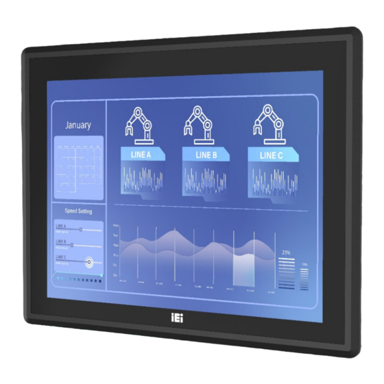
PPC2-Cxxx-EHL Series Panel PC 1.1 Overview Figure 1-1: PPC2-Cxxx-EHL Series Panel PC The PPC2-Cxxx-EHL series is a quad-core Intel® Celeron® processor J6412 powered f lat bezel panel PC with a rich variety of f unctions and peripherals. The rugged and trendy design can be applied in harsh industrial environments and enriches aesthetic experience at the same time. -
Page 17: Model Variation
PPC2-Cxxx-EHL Series Panel PC 1.2 Model Variation The PPC2-Cxxx-EHL Series is preinstalled with Intel® Celeron® processor J6412, which has a 10 W TDP. The model numbers and model variations are listed below. Model Size I/O Port PPC2-C08-EHL-J1/8G-R10 4 x USB, 2 x COM 8”... -
Page 18: Front Panel
PPC2-Cxxx-EHL Series Panel PC 1.4 Front Panel The f ront side of the PPC2-Cxxx-EHL Series (Figure 1-2) is a f lat panel LCD touchscreen surrounded by an aluminum f rame. Figure 1-2: Front View 1.5 Rear Panel The rear panel has a f an vent, f our VESA 75/100 mounting holes and several retention screws. -
Page 19: Bottom Panel
PPC2-Cxxx-EHL Series Panel PC 1.6 Bottom Panel The bottom panel has the f ollowing interf aces: Figure 1-4: PPC2-C08-EHL Bottom View Figure 1-5: PPC2-C10-EHL Bottom View Figure 1-6: PPC2-C12-EHL Bottom View Page 5... -
Page 20: Figure 1-7: Ppc2-C15/Cw15/C17/C19/Cw19/Cw22-Ehl Bottom View
PPC2-Cxxx-EHL Series Panel PC Figure 1-7: PPC2-C15/CW15/C17/C19/CW19/CW22-EHL Bottom View WARNING: Before installing the operating system, the user must enter the Boot BIOS menu f irst and choose which operating system will be installed. Otherwise, the USB 2.0 and USB 3.2 Gen 1 ports may not be detected. Page 6... -
Page 21: Dimensions
PPC2-Cxxx-EHL Series Panel PC 1.7 Dimensions 1.7.1 PPC2-C08-EHL Dimensions Figure 1-8: PPC2-C08-EHL Dimensions (Unit: mm) Page 7... -
Page 22: Ppc2-C10-Ehl Dimensions
PPC2-Cxxx-EHL Series Panel PC 1.7.2 PPC2-C10-EHL Dimensions Figure 1-9: PPC2-C10-EHL Dimensions (mm) Page 8... -
Page 23: Ppc2-C12-Ehl Dimensions
PPC2-Cxxx-EHL Series Panel PC 1.7.3 PPC2-C12-EHL Dimensions Figure 1-10: PPC2-C12-EHL Dimensions (mm) Page 9... -
Page 24: Ppc2-C15-Ehl Dimensions
PPC2-Cxxx-EHL Series Panel PC 1.7.4 PPC2-C15-EHL Dimensions Figure 1-11: PPC2-C15-EHL Dimensions (mm) Page 10... -
Page 25: Ppc2-Cw15-Ehl Dimensions
PPC2-Cxxx-EHL Series Panel PC 1.7.5 PPC2-CW15-EHL Dimensions Figure 1-12: PPC2-CW15-EHL Dimensions (mm) Page 11... -
Page 26: Ppc2-C17-Ehl Dimensions
PPC2-Cxxx-EHL Series Panel PC 1.7.6 PPC2-C17-EHL Dimensions Figure 1-13: PPC2-C17-EHL Dimensions (mm) Page 12... -
Page 27: Ppc2-C19-Ehl Dimensions
PPC2-Cxxx-EHL Series Panel PC 1.7.7 PPC2-C19-EHL Dimensions Figure 1-14: PPC2-C19-EHL Dimensions (mm) Page 13... -
Page 28: Ppc2-Cw19-Ehl Dimensions
PPC2-Cxxx-EHL Series Panel PC 1.7.8 PPC2-CW19-EHL Dimensions Figure 1-15: PPC2-CW19-EHL Dimensions (mm) Page 14... -
Page 29: Ppc2-Cw22-Ehl Dimensions
PPC2-Cxxx-EHL Series Panel PC 1.7.9 PPC2-CW22-EHL Dimensions Figure 1-16: PPC2-CW22-EHL Dimensions (mm) Page 15... -
Page 30: Specifications
PPC2-Cxxx-EHL Series Panel PC 1.8 Specifications The technical specif ications are listed in Table 1-2 & Table 1-3 & Table 1-4 . PPC2-C08 PPC2-C10 PPC2-C12 LCD Display 8" (4:3) 10.4" (4:3) 12” (4:3) Max. Resolution 800 (W) x 600 (H) 800 (W) x 600 (H) 1024 (W) x 768 (H) Brightness... -
Page 31: Table 1-2: Ppc2-C08/C10/C12 Specifications
PPC2-Cxxx-EHL Series Panel PC PPC2-C08 PPC2-C10 PPC2-C12 Humidity 10% ~ 95%, non-condensing Safety and EMC CE, FCC Class A ErP 2009/125/EC Dimensions 222.2 x 182.2 x 49.7 285.2 x 232.4 x 49.9 322.2 x 262.2x 53 (H x W x D) (Unit: mm) Net Weight 1.610kg 2.355kg... - Page 32 PPC2-Cxxx-EHL Series Panel PC PPC2-C15 PPC2-CW15 PPC2-C17 Contrast Ratio 800:1 500:1 800:1 LCD Color 16.2M 16.2M 16.7M Pixel Pitch (Unit: mm) 0.297 x 0.297 0.252x0.252 0.26x0.26 Viewing Angle (H-V) 170°/150° 170°/160° 170°/160° Backlight MTBF 70,000 hours 50000 hours 50,000 hours SBC Model PPC2MB2-EHL-RC-R10+PPC2-XIO-02-R10 CPU (SoC)
-
Page 33: Table 1-3: Ppc2-C15/Cw15/C17 Specifications
PPC2-Cxxx-EHL Series Panel PC PPC2-C15 PPC2-CW15 PPC2-C17 1 x HDMI output 2 x 2.5GbE RJ-45 2 x USB 3.2 Gen 2x1 (10Gb/s) 2 x USB 2.0 1 x RS-232/422/485 1 x RS-232 1 x 12V-24V power jack I/O Ports, Switches 1 x Power terminal block (2-pin) and Buttons 1 x AT/ATX switch... - Page 34 PPC2-Cxxx-EHL Series Panel PC PPC2-C19 PPC2-CW19 PPC2-CW22 Surface hardness: ≥7H Touch Controller Projected capacitive type: EETI 80 Drive Bay 1 x 2.5” HDD/SSD drive bay Ethernet 2 x 2.5GbE LAN via Intel I225-V 1 x M.2 2242/2280 B key (PCIe Gen3 x1 + USB 3.0) Expansion 1 x M.2 2242 M key (PCIe Gen3 x2) Mounting...
-
Page 35: Table 1-4: Ppc2-C19/Cw19/Cw22 Specifications
PPC2-Cxxx-EHL Series Panel PC PPC2-C19 PPC2-CW19 PPC2-CW22 1 x Reset button 1 x Clear CMOS button PPC2-XIO-01-R10: 2 x USB 2.0 2 x RS-232 DB9 1 x M.2 B key 2242/2280 (PCIe Gen3 x 2 + USB 2.0) Table 1-4: PPC2-C19/CW19/CW22 Specifications Page 21... -
Page 36: Unpacking
PPC2-Cxxx-EHL Series Panel PC Chapter Unpacking Page 22... -
Page 37: Unpacking
PPC2-Cxxx-EHL Series Panel PC 2.1 Unpacking To unpack the panel PC, f ollow the steps below: WARNING! The f ront side LCD screen has a protective plastic cover stuck to the screen. Only remove the plastic cover af ter the panel PC has been properly installed. -
Page 38: Packing List
PPC2-Cxxx-EHL Series Panel PC 2.2 Packing List The PPC2-Cxxx-EHL Series panel PC is shipped with the f ollowing components: Quantity Item Image PPC2-Cxxx-EHL Series panel PC Power cord (part number varies by regions) Power adapter Screw pack Panel mount kit pack Table 2-1: Packing List If any of the above items are missing or damaged, contact the distributor or sales representative immediately. -
Page 39: Installation
PPC2-Cxxx-EHL Series Panel PC Chapter Installation Page 25... -
Page 40: Anti-Static Precautions
PPC2-Cxxx-EHL Series Panel PC 3.1 Anti-static Precautions WARNING: Failure to take ESD precautions during the maintenanc e of the panel PC may result in permanent damage to the panel PC and severe injury to the user. Electrostatic discharge (ESD) can cause serious damage to electronic components, including the PPC2-Cxxx-EHL Series. -
Page 41: Preinstalled Components
PPC2-Cxxx-EHL Series Panel PC When installing the panel PC, please f ollow the precautions listed below: ▪ Power turned off: When installing the panel PC, make sure the power is off. Failing to turn off the power may cause severe injury to the body and/or damage to the system. -
Page 42: Removing The
PPC2-Cxxx-EHL Series Panel PC Step 5: Configure the system. 3.5 Removing the Back Cover Remove the back cover retention screws on the back cover. Lif t the cover up to remove. NOTE: The number of retention screws on the chassis varies by models. Figure 3-1: PPC2-Cxxx-EHL Back Cover Retention Screws Page 28... -
Page 43: Hdd Installation (Optional)
PPC2-Cxxx-EHL Series Panel PC 3.6 HDD Installation (Optional) To install a 2.5” HDD into the PPC2-Cxxx-EHL Series (model of 12" or above), please f ollow the steps below: Step 1: Remove the back cover. See Section 3.5. Step 2: Remove the HDD bracket from the PPC2-Cxxx-EHL Series. The HDD bracket is secured on the panel PC with four retention screws (Figure 3-2). -
Page 44: Figure 3-3: Hdd Retention Screws
PPC2-Cxxx-EHL Series Panel PC Figure 3-3: HDD Retention Screws Step 4: Reinstall the HDD bracket into the PPC2-Cxxx-EHL Series and fasten the four hard drive bracket screws (Figure 3-4).Connect the SATA and SATA power cables. Figure 3-4: PPC2-Cxxx-EHL HDD Installation Page 30... -
Page 45: Module Installation (Optional)
PPC2-Cxxx-EHL Series Panel PC 3.7 M.2 Module Installation (Optional) The M.2 M-key slot allows installation of M.2 2280 cards. To install an M.2 card, please f ollow the steps below. Step 1: Remove the back cover. See Section 3.5. 557H Step 2: Locate the M.2 slot as shown in Figure 3-5. -
Page 46: Figure 3-6: Press The End Of The M.2 Retaining Clip
PPC2-Cxxx-EHL Series Panel PC Figure 3-6: Press the end of the M.2 retaining clip Step 4: Insert M.2 card. The notch at the end of the M.2 card needs to be aligned with the notch of the fixed buckle (Figure 3-7). Figure 3-7: Insert M.2 Card Step 5: Secure the M.2 card. -
Page 47: At/Atx Mode Selection
PPC2-Cxxx-EHL Series Panel PC Figure 3-8: Securing the M.2 card 3.8 AT/ATX Mode Selection AT and ATX power modes can both be used on the PPC2-Cxxx-EHL Series panel PC. The selection is made through an AT/A TX switch on the I/O interf ace panel. The system is set to ATX mode by def ault. -
Page 48: Mounting The System
PPC2-Cxxx-EHL Series Panel PC 3.9 Mounting the System WARNING! When mounting the PPC2-Cxxx-EHL Series panel PC, it is advisable to have more than one person help with the installation to prevent accidental damage to the panel and avoid personal injury. The methods of mounting the PPC2-Cxxx-EHL Series are: ▪... -
Page 49: Figure 3-10: Wall-Mounting Bracket
PPC2-Cxxx-EHL Series Panel PC Figure 3-10: Wall-mounting Bracket Step 6: Insert the four monitor mounting screws provided in the wall mounting kit into the four screw holes on the real panel of the monitor and tighten until the screw shank is secured against the rear panel (Figure 3-11). Step 7: Align the mounting screws on the monitor rear panel with the mounting holes on the bracket. -
Page 50: Figure 3-11: Mount The Chassis
PPC2-Cxxx-EHL Series Panel PC Figure 3-11: Mount the Chassis Step 9: Secure the panel PC with the wall-mounting kit. To do this, stick the protective cushion to the wall-mounting kit first. Then, put the wall-mounting kit on the top panel of the panel PC. Carefully mark the location of the wall-mounting kit screw holes on the wall. -
Page 51: Figure 3-12: Secure The Chassis
PPC2-Cxxx-EHL Series Panel PC Figure 3-12: Secure the Chassis Page 37... -
Page 52: Panel, Rack And Cabinet Installation
PPC2-Cxxx-EHL Series Panel PC 3.9.2 Panel, Rack and Cabinet Installation To mount the PPC2-Cxxx-EHL Series panel PC into a panel, please f ollow steps 1-5. For rack and cabinet installation, please f ollow Steps 1-7. NOTE: For the PPC-XXX-EHL Series panel PC, all mounting kit must be installed (Figure 3-13). -
Page 53: Figure 3-14: Ppc2-C08-Ehl Panel Cutout Dimensions
PPC2-Cxxx-EHL Series Panel PC Figure 3-14: PPC2-C08-EHL Panel Cutout Dimensions Figure 3-15: PPC2-C10-EHL Panel Cutout Dimensions Page 39... -
Page 54: Figure 3-16: Ppc2-C12-Ehl Panel Cutout Dimensions
PPC2-Cxxx-EHL Series Panel PC Figure 3-16: PPC2-C12-EHL Panel Cutout Dimensions Figure 3-17: PPC2-C15-EHL Panel Cutout Dimensions Figure 3-18: PPC2-C17-EHL Panel Cutout Dimensions Page 40... -
Page 55: Figure 3-19: Ppc2-C19-Ehl Panel Cutout Dimensions
PPC2-Cxxx-EHL Series Panel PC Figure 3-19: PPC2-C19-EHL Panel Cutout Dimensions Figure 3-20: PPC2-CW15-EHL Panel Cutout Dimensions Figure 3-21: PPC2-CW19-EHL Panel Cutout Dimensions Page 41... -
Page 56: Figure 3-22: Ppc2-Cw22-Ehl Panel Cutout Dimensions
PPC2-Cxxx-EHL Series Panel PC Figure 3-22: PPC2-CW22-EHL Panel Cutout Dimensions Step 3: Slide the PPC2-Cxxx-EHL Series through the hole until the aluminum frame is flush against the panel (Figure 3-23). Figure 3-23: Machine mounted to panel Step 4: Insert the panel mount kit into the prefabricated holes along the rear edge of the PPC2-Cxxx-EHL series (Figure 3-24). -
Page 57: Figure 3-24: Installation Panel Mount Kit
PPC2-Cxxx-EHL Series Panel PC Figure 3-24: Installation Panel Mount Kit Step 5: Tighten the screws that pass through the mounting clamps until the plastic caps at the front of all the screws are firmly secured to the panel (Figure 3-25). Figure 3-25: Tighten the Mounting Screws Step 6: Slide the PPC2-Cxxx-EHL series with the attached rack/cabinet bracket into a... -
Page 58: Arm Mounting
PPC2-Cxxx-EHL Series Panel PC Figure 3-26: Install into a Rack/Cabinet Step 7: Once the flat panel PC with the attached rack/cabinet bracket has been properly inserted into the rack or cabinet, secure the front of the rack/cabinet bracket to the front of the rack or cabinet (Figure 3-26). 3.9.3 Arm Mounting The PPC2-Cxxx-EHL Series is VESA (Video Electronics Standards Association) compliant and can be mounted on an arm with a 75/100 mm interf ace pad. -
Page 59: Figure 3-27: Arm Mounting Retention Screw Holes
PPC2-Cxxx-EHL Series Panel PC Step 2: Once the mounting arm has been firmly attached to its surface, lift the PPC2-Cxxx-EHL Series panel PC onto the interface pad of the mounting arm. Step 3: Align the retention screw holes on the mounting arm interface with those in the PPC2-Cxxx-EHL Series panel PC. -
Page 60: Stand Mounting
PPC2-Cxxx-EHL Series Panel PC Figure 3-28: Arm Mounting (ARM-XX-RS) 3.9.4 Stand Mounting To mount the PPC2-Cxxx-EHL Series using the stand mounting kit, please follow the steps below. Step 1: Locate the screw holes on the rear of the PPC2-Cxxx-EHL Series. This is where the bracket will be attached. -
Page 61: Serial Device Connection
PPC2-Cxxx-EHL Series Panel PC Figure 3-29: Stand Mounting Retention Screw Holes Step 2: Align the bracket with the screw holes. Step 3: To secure the bracket to the PPC2-Cxxx-EHL Series, insert the retention screws into the screw holes and tighten them.S t e p 0 : Figure 3-30: Stand Mounting (Stand-Cxx) 3.10 Serial Device Connection... -
Page 62: Serial Ports
PPC2-Cxxx-EHL Series Panel PC Figure 3-31: Serial Port Locations of PPC2-C15/CW15/C17/ C19/CW19/ CW22-EHL 3.10.1 RS-232 Serial Ports The pinouts of the RS-232 serial ports are listed in the f ollowing table. PIN NO. DESCRIPTION PIN NO. DESCRIPTION Table 3-2: RS-232 Serial Port Pinouts Page 48... -
Page 63: Rs-232/422/485 Serial Port
PPC2-Cxxx-EHL Series Panel PC 3.10.2 RS-232/422/485 Serial Port The pinouts of the RS-232/422/485 serial ports are listed in the f ollowing table. PIN NO. RS-232 RS-422 RS-485 TXD422- TXD485- TXD422+ TXD485+ RXD422+ RXD422- Table 3-3: RS-232/422/485 Serial Port (COM3) Pinouts 3.11 Powering On the System To power on the system, f ollow the steps below: Step 1:... -
Page 64: Reset The System
PPC2-Cxxx-EHL Series Panel PC Figure 3-33: Power Connectors and Power Switch 3.12 Reset the System The reset button enables users to reboot the system when the system is turned on. The reset button location is shown in Figure 3-34. Press the reset button to reboot the system. Figure 3-34: Reset Button Location 3.13 Clear CMOS If the PPC2-Cxxx-EHL Series f ails to boot due to improper BIOS settings, the clear CMOS... -
Page 65: Available Drivers
PPC2-Cxxx-EHL Series Panel PC 3.14 Available Drivers All the drivers for the PPC2-Cxxx-EHL Series are available on IEI Resource Download Cent er (https://download.ieiworld.com). Type PPC2-Cxxx-EHL Series and press Enter to f ind all the relevant sof tware, utilities, and documentation. Figure 3-36: IEI Resource Download Center The f ollowing drivers can be installed on the Windows 10/11 operating system: ▪... -
Page 66: Driver Download
PPC2-Cxxx-EHL Series Panel PC 3.14.1 Driver Download To download drivers f rom IEI Resource Download Center, f ollow the steps below. Step 1: Go to https://download.ieiworld.com. Type PPC2-Cxxx-EHL Series and press Enter. Step 2: All product-related software, utilities, and documentation will be listed. You can choose Driver to filter the result. - Page 67 PPC2-Cxxx-EHL Series Panel PC NOTE: To install software f rom the downloaded ISO image f ile in Windows 10 or 11, double-click the ISO f ile to mount it as a virtual drive to view its content. Page 53...
-
Page 68: System Maintenance
PPC2-Cxxx-EHL Series Panel PC Chapter System Maintenance Page 54... -
Page 69: System Maintenance Introduction
PPC2-Cxxx-EHL Series Panel PC 4.1 System Maintenance Introduction The f ollowing system components may require maintenance. ▪ Motherboard ▪ Storage module If these components f ail, they must be replaced. Please contact the system reseller or vendor to purchase replacement parts. Replacement instructions for the above listed components are described below. -
Page 70: Interface Connectors
PPC2-Cxxx-EHL Series Panel PC Chapter Interface Connectors Page 56... -
Page 71: Peripheral Interface Connectors
PPC2-Cxxx-EHL Series Panel PC 5.1 Peripheral Interface Connectors The PPC2-Cxxx-EHL S eries panel P C motherboard comes with a number of peripheral interf ace connectors and conf iguration jumpers. The connector locations are shown in Figure 5-1 and Figure 5-2. The Pin 1 locations of the on-board connectors are also indicated in the diagrams. -
Page 72: Internal Peripheral Connectors
PPC2-Cxxx-EHL Series Panel PC 5.2 Internal Peripheral Connectors Internal peripheral connectors are f ound on the motherboard and are only accessible when the motherboard is outside of the chassis. The table below shows a list of the peripheral interf ace connectors on the PPC2-Cxxx-EHL Series motherboard. Pinouts of these connectors can be f ound in the f ollowing sections. -
Page 73: Battery Connector (Bat2)
PPC2-Cxxx-EHL Series Panel PC Rotation Signal PWM Control Signal Table 5-2: Fan connector (CPU_FAN1) Pinouts 5.2.2 Battery connector (BAT2) PIN NO. DESCRIPTION PIN NO. DESCRIPTION +V3.3A_DSW Table 5-3: Battery connector (BAT2) Pinouts 5.2.3 EC debug port (EC_DEBUG1) PIN NO. DESCRIPTION PIN NO. -
Page 74: Sata 6Gb/S Connectors (Sata2)
PPC2-Cxxx-EHL Series Panel PC Table 5-6: Capacitive touch port (TOUCH_USB) Pinouts 5.2.6 SATA 6Gb/s connectors (SATA2) PIN NO. DESCRIPTION PIN NO. DESCRIPTION SATA_TX+ SATA_TX- SATA_RX- SATA_RX+ Table 5-7: SATA 6Gb/s connectors (SATA2) Pinouts 5.2.7 SATA power connectors (SATA2_PWR) PIN NO. DESCRIPTION Table 5-8: SATA power connectors (SATA2_PWR) Pinouts 5.2.8 Resistive touch port (DMC6000_CN1) -
Page 75: B-Key Slot (M2_1)
PPC2-Cxxx-EHL Series Panel PC SATA_RX+ SATA_RX- SATA_TX+ SATA_TX- Table 5-10: ISATA connector (SATA1) Pinouts 5.2.10 M.2 B-Key slot (M2_1) PIN NO. DESCRIPTION PIN NO. DESCRIPTION +3.3V +3.3V USB_D+ USB_D- Module Key Module Key Module Key Module Key Module Key Module Key Module Key Module Key USB3_RX_N... -
Page 76: M-Key Slot (M2_M1)
PPC2-Cxxx-EHL Series Panel PC PCIE_RXN PCIE_RXP PCIE_TXN PCIE_TXP PERST# CLKREQ_N CLKN PCIE_WAKE# CLKP SUSCLK +3.3V +3.3V +3.3V Table 5-11: M.2 B-Key slot (M2_1) Pinouts 5.2.11 M.2 M-Key slot (M2_M1) PIN NO. DESCRIPTION PIN NO. DESCRIPTION +3.3V +3.3V DAS/DSS# +3.3V +3.3V +3.3V +3.3V Page 62... -
Page 77: Idpm Connector (J_M2_Edp_Lvds)
PPC2-Cxxx-EHL Series Panel PC PCIE_RXN5 PCIE_RXP5 PCIE_TXN5 PCIE_TXP5 DEVSLP I2C_CLK PCIE_RXN4 I2C_DAT PCIE_RXP4 PCIE_TXN4 PCIE_TXP4 PERST# CLKN PCIE_WAKE# CLKP Module Key Module Key Module Key Module Key Module Key Module Key Module Key Module Key +3.3V +3.3V +3.3V +3.3V Table 5-12: M.2 M-Key slot (M2_M1) Pinouts 5.2.12 IDPM connector (J_M2_EDP_LVDS) PIN NO. - Page 78 PPC2-Cxxx-EHL Series Panel PC +V3.3A +V3.3A +V3.3A +V3.3A +V3.3A Module Key Module Key Module Key Module Key Module Key Module Key Module Key Module Key +V3.3S Display Detect PIN +V3.3S Display Detect PIN +V3.3S +V3.3S EDP_TX3_DN +V12S EDP_TX3_DP +V12S +V12S EDP_TX2_DN +V12S EDP_TX2_DP...
-
Page 79: Table 5-13: Idpm Connector (J_M2_Edp_Lvds) Pinouts
PPC2-Cxxx-EHL Series Panel PC +V12A +V12A +V12A +V12A Table 5-13: IDPM connector (J_M2_EDP_LVDS) Pinouts Page 65... -
Page 80: Flash Mode Connector (J_Flash1)
PPC2-Cxxx-EHL Series Panel PC 5.2.13 Flash mode connector (J_FLASH1) PIN NO. DESCRIPTION LOW = Disabled (No override) Default High = Enabled (OVERIDE) Table 5-14: Flash mode connector (J_FLASH1) Pinouts 5.2.14 SPI flash (EC) connector (EC_SPI1) PIN NO. DESCRIPTION PIN NO. DESCRIPTION CS_EC +3.3V... -
Page 81: Power Button Connector (Pwr_Btn1)
PPC2-Cxxx-EHL Series Panel PC 5.2.17 Power button connector (PWR_BTN1) PIN NO. DESCRIPTION Table 5-18: Reset Button Connector (RST_BTN2) Pinouts 5.3 External Interface Panel Connectors The table below lists the rear panel connectors on the PPC2-Cxxx-EHL Series motherboard. Pinouts of these connectors can be f ound in the f ollowing sections. Connector Type Label... -
Page 82: Gbe Connector (Lan1, Lan2)
PPC2-Cxxx-EHL Series Panel PC PIN NO. DESCRIPTION PIN NO. DESCRIPTION HDMI_SCL HDMI_SDA HDMI_HPD Table 5-20: HDMI Connector (HDMI1) Pinouts 5.3.2 2.5GbE Connector (LAN1, LAN2) PIN NO. DESCRIPTION PIN NO. DESCRIPTION MDIA0- MDIA2+ MDIA0+ MDIA1+ MDIA1- MDIA3- MDIA2- MDIA3+ Table 5-21: 2.5GbE Connector (LAN1, LAN2) Pinouts 5.3.3 USB 2.0 Connectors (USB2_CON1) PIN NO. - Page 83 PPC2-Cxxx-EHL Series Panel PC USB3_TX- USB3_TX- USB3_TX+ USB3_TX+ Table 5-23: USB 3.2 Gen 1 Connector (USB3_CON1) Pinouts Page 69...
-
Page 84: A Regulatory Compliance
PPC2-Cxxx-EHL Series Panel PC Appendix Regulatory Compliance Page 70... - Page 85 PPC2-Cxxx-EHL Series Panel PC DECLARATION OF CONFORMITY This equipment is in conf ormity with the f ollowing EU directives: EMC Directive (2014/30/EU) ◼ Low-Voltage Directive (2014/35/EU) ◼ RoHS II Directive (2011/65/EU, 2015/863/EU) ◼ Ecodesign Directive 2009/125/EC ◼ If the user modif ies and/or install other devices in the equipment, the CE conformity declaration may no longer apply.
- Page 86 PPC2-Cxxx-EHL Series Panel PC Español [Spanish] IEI Integration Corp declara que el equipo cumple con los requisitos esenciales y cualesquiera otras disposiciones aplicables o exigibles de la Directiva 2014/53/EU. Ελληνική [Greek] IEI Integration Corp ΔΗΛΩΝΕΙ ΟΤΙ ΕΞΟΠΛΙΣΜΟΣ ΣΥΜΜΟΡΦΩΝΕΤΑΙ ΠΡΟΣ ΤΙΣ ΟΥΣΙΩΔΕΙΣ...
- Page 87 PPC2-Cxxx-EHL Series Panel PC Româna [Romanian] IEI Integration Corp declară că acest echipament este in conformitate cu cerinţele esenţiale şi cu celelalte prevederi relevante ale Directivei 2014/53/EU. Slovensko [Slovenian] IEI Integration Corp izjavlja, da je ta opreme v skladu z bistvenimi zahtevami in ostalimi relevantnimi določili direktive 2014/53/EU.
- Page 88 PPC2-Cxxx-EHL Series Panel PC FCC WARNING This equipment complies with Part 15 of the FCC Rules. Operation is subject to the f ollowing two conditions: This device may not cause harmful interference, and ◼ This device must accept any interference received, including interference ◼...
-
Page 89: B Safety Precautions
PPC2-Cxxx-EHL Series Panel PC Appendix Safety Precautions Page 75... -
Page 90: Safety Precautions
PPC2-Cxxx-EHL Series Panel PC WARNING: The precautions outlined in this chapter should be strictly followed. Failure to f ollow these precautions may result in permanent damage to the PPC2-Cxxx-EHL Series. B.1 Safety Precautions Please f ollow the saf ety precautions outlined in the sections that f ollow: B.1.1 General Safety Precautions Please ensure the f ollowing saf ety precautions are adhered to at all times. -
Page 91: Anti-Static Precautions
PPC2-Cxxx-EHL Series Panel PC If considerable amounts of dust, water, or fluids enter the device, turn off ▪ the power supply immediately, unplug the power cord, and contact the PPC2-Cxxx-EHL Series vendor. ▪ DO NOT: Drop the device against a hard surf ace. Strike or exert excessive f orce onto the LCD panel. -
Page 92: Product Disposal
PPC2-Cxxx-EHL Series Panel PC B.1.3 Product Disposal CAUTION: Risk of explosion if battery is replaced by an incorrect type. Only certif ied engineers should replace the on-board battery. Dispose of used batteries according to instructions and local regulations. ▪ Outside the European Union–If you wish to dispose of used electrical and electronic products outside the European Union, please contact your local authority so as to comply with the correct disposal method. -
Page 93: Maintenance And Cleaning Precautions
PPC2-Cxxx-EHL Series Panel PC B.2 Maintenance and Cleaning Precautions When maintaining or cleaning the PPC2-Cxxx-EHL Series, please f ollow the guidelines below. WARNING: ▪ For safety reasons, turn-off the power and unplug the panel PC before cleaning. ▪ If you dropped any material or liquid such as water onto the panel PC when cleaning, unplug the power cable immediately and contact your dealer or the nearest service center. - Page 94 PPC2-Cxxx-EHL Series Panel PC Cloth– Although paper towels or tissues can be used, a soft, clean piece of ▪ cloth is recommended when cleaning the device. ▪ Water or rubbing alcohol–A cloth moistened with water or rubbing alcohol can be used to clean the device. ▪...
-
Page 95: C Watchdog Timer
PPC2-Cxxx-EHL Series Panel PC Appendix Watchdog Timer Page 81... - Page 96 PPC2-Cxxx-EHL Series Panel PC NOTE: The f ollowing discussion applies to DOS environment. IEI support is contacted or the IEI website visited for specif ic drivers f or more sophisticated operating systems, e.g., Windows and Linux. The Watchdog Timer is provided to ensure that standalone sy stems can always recover f rom catastrophic conditions that cause the CP U to crash.
- Page 97 PPC2-Cxxx-EHL Series Panel PC NOTE: When exiting a program it is necessary to disable the Watchdog Timer, otherwise the system resets. Example program: ; INITIAL TIMER PERIOD COUNTER W_LOOP: AX, 6F02H ;setting the time-out value BX, 05 ;time-out value is 5 seconds ;...
-
Page 98: D Hazardous Materials Disclosure
PPC2-Cxxx-EHL Series Panel PC Appendix Hazardous Materials Disclosure Page 84... - Page 99 PPC2-Cxxx-EHL Series Panel PC The details provided in this appendix are to ensure that the product is compliant with the Peoples Republic of China (China) RoHS standards. The table below acknowledges the presences of small quantities of certain materials in the product, and is applicable to China RoHS only.
- Page 100 PPC2-Cxxx-EHL Series Panel PC 此附件旨在确保本产品符合中国 RoHS 标准。以下表格标示此产品中某有毒物质的含量符 合中国 RoHS 标准规定的限量要求。 本产品上会附有”环境友好使用期限”的标签,此期限是估算这些物质”不会有泄漏或突变”的 年限。本产品可能包含有较短的环境友好使用期限的可替换元件,像是电池或灯管,这些元 件将会单独标示出来。 部件名称 有毒有害物质或元素 铅 汞 镉 六价铬 多溴联苯 多溴二苯 醚 (Pb) (Hg) (Cd) (CR(VI)) (PBB) (PBDE) 壳体 显示 印刷电路板 金属螺帽 电缆组装 风扇组装 电力供应组装 电池 O: 表示该有毒有害物质在该部件所有物质材料中的含量均在 SJ/T 11363-2006 (现由 GB/T 26572-2011 取代) 标准规定的限量要求以下。...
Need help?
Do you have a question about the PPC2-C-EHL Series and is the answer not in the manual?
Questions and answers