Table of Contents
Advertisement
Quick Links
Advertisement
Table of Contents

Related Manuals for IEI Technology PPC2 ADLP Series PPC2-C104-ADLP-i3/8G


Summary of Contents for IEI Technology PPC2 ADLP Series PPC2-C104-ADLP-i3/8G
- Page 1 PPC2-xxx-ADLP Panel PC MODEL: PPC2-xxx-ADLP Series equips Panel PC Intel® Alder Lake-P Core™ i7/i5/i3 Processor, 8GB LPDDR4X on-board, one M.2 M key 2242 slot, one M.2 M key 2280 slot User Manual User Manual Page 1 Rev. 1.00 - September 22, 2023...
-
Page 2: Revision
PPC2-xxx-ADLP Panel PC Revision Date Version Changes September 22, 2023 1.00 Initial release Page 2... -
Page 3: Safety Instructions
PPC2-xxx-ADLP Panel PC Safety Instructions Warning! Read the user manual before connecting the system to the power source. Vorsicht! Bitte lesen Sie die Bedienungsanleitung, bevor Sie das System an eine Stromquelle anschließen. Attention! Avant de brancher le système à la source d'alimentation, consultez le mode d'emploi. - Page 4 PPC2-xxx-ADLP Panel PC Warning! Use only the adapter and power cord approved for this system. Use of another type of adapter may risk fire or explosion. Please refer to the user manual for the power adapter specifications. Vorsicht! Nur zugelassene Netzteile und Netzkabel dürfen verwendet werden. Die Benutzung von anderen Netzteilen kann einen Brand oder eine Explosion zur Folge haben.
-
Page 5: Copyright
PPC2-xxx-ADLP Panel PC Copyright COPYRIGHT NOTICE The information in this document is subject to change without prior notice in order to improve reliability, design and function and does not represent a commitment on the part of the manufacturer. In no event will the manufacturer be liable for direct, indirect, special, incidental, or consequential damages arising out of the use or inability to use the product or documentation, even if advised of the possibility of such damages. -
Page 6: Manual Conventions
PPC2-xxx-ADLP Panel PC Manual Conventions WARNING Warnings appear where overlooked details may cause damage to the equipment or result in personal injury. Warnings should be taken seriously. CAUTION Cautionary messages should be heeded to help reduce the chance of losing data or damaging the product. NOTE These messages inform the reader of essential but non-critical information. -
Page 7: Table Of Contents
PPC2-xxx-ADLP Panel PC Table of Contents REVISION ......................... 2 SAFETY INSTRUCTIONS ..................... 3 COPYRIGHT ........................5 MANUAL CONVENTIONS .................... 6 TABLE OF CONTENTS ....................7 LIST OF FIGURES ......................11 LIST OF TABLES ......................13 1 INTRODUCTION ......................15 1.1 O ........................ - Page 8 PPC2-xxx-ADLP Panel PC 2.2 P ......................37 ACKING 2.3 O ...................... 38 PTIONAL TEMS 3 INSTALLATION ......................39 3.1 A ..................40 STATIC RECAUTIONS 3.2 I ................... 40 NSTALLATION RECAUTIONS 3.3 I ............. 41 NSTALLATION AND ONFIGURATION TEPS 3.4 R ..................
- Page 9 PPC2-xxx-ADLP Panel PC 5.1.4 Unable to Reboot after Configuration Changes ..........70 5.1.5 BIOS Menu Bar ....................70 5.2 M ........................71 5.3 A ....................... 73 DVANCED 5.3.1 CPU Configuration ..................74 5.3.2 Trusted Computing ................... 78 5.3.3 RTC Wake Setting ..................... 79 5.3.4 F81966 Super IO Configuration ..............
- Page 10 PPC2-xxx-ADLP Panel PC 6.2.13 LVDS Panel Connector (LVDS1) ............... 124 6.2.14 LVDS Backlight Power (INV1) ..............124 6.2.15 CPU Fan Connector (CPU_FAN1).............. 124 6.2.16 MPS PWM IC Programmer Connector (J1) ..........125 6.2.17 Flash Descriptor Security Override (ME_FLASH1) ........125 6.2.18 Chassis Pin Header (J_CHASSIS1) ............
-
Page 11: List Of Figures
PPC2-xxx-ADLP Panel PC List of Figures Figure 1-1: PPC2-xxx-ADLP Series Panel PC ................16 Figure 1-2: Front View ........................19 Figure 1-3: Rear View ........................19 Figure 1-4: Bottom Panel ......................20 Figure 1-5: PPC2-C104-ADLP Dimensions (mm) ...............26 Figure 1-6: PPC2-C121-ADLP Dimensions (mm) ...............27 Figure 1-7: PPC2-CW133-ADLP Dimensions (mm) ..............28 Figure 1-8: PPC2-C150-ADLP Dimensions (mm) ...............29 Figure 1-9: PPC2-CW156-ADLP Dimensions (mm) ..............30... - Page 12 PPC2-xxx-ADLP Panel PC Figure 3-19: PPC2-CW133-ADLP Panel Cutout Dimensions ............54 Figure 3-20: PPC2-C150-ADLP Panel Cutout Dimensions ............55 Figure 3-21: PPC2-C170-ADLP Panel Cutout Dimensions ............55 Figure 3-22: PPC2-C190-ADLP Panel Cutout Dimensions ............55 Figure 3-23: PPC2-CW156-ADLP Panel Cutout Dimensions ............56 Figure 3-24: PPC2-CW185-ADLP Panel Cutout Dimensions ............56 Figure 3-25: PPC2-CW215-ADLP Panel Cutout Dimensions ............56 Figure 3-26: Machine mounted to panel ..................57 Figure 3-27: Installation Panel Mount Kit ...................57...
-
Page 13: List Of Tables
PPC2-xxx-ADLP Panel PC List of Tables Table 1-1: Model Variation ......................18 Table 1-2: System Specifications ....................22 Table 1-3: System Specifications ....................24 Table 1-4: System Specifications ....................25 Table 2-1: Packing List .........................37 Table 2-2: Optional Items ......................38 Table 5-1: BIOS Navigation Keys ....................68 Table 5-2: BIOS On-screen Navigation Keys ................69 Table 6-1: Peripheral Interface Connectors ................117 Table 6-2: Touch Panel Connector (J_TOUCH1) Pinouts ............117... - Page 14 PPC2-xxx-ADLP Panel PC Table 6-24: Backlight VCC Selection (J_BL_VCC)..............126 Table 6-25: LVDS Power Selection (J_VLVDS1) ..............127 Table 6-26: Flash Descriptor Security Override ..............127 Table 6-27: External Interface Panel Connectors ..............127 Table 6-28: External Serial Port Connector (COM1/2/3/4) Pinouts ........128 Table 6-29: LAN Connector (LAN1/2) Pinouts .................128 Table 6-30: HDMI1 Connector (HDMI1) Pinouts ...............129 Table 6-31: USB 2.0 Connectors (USB5) Pinouts ..............129 Table 6-32: USB 3.2 Gen 1 Connectors (USB3/4) Pinouts ............129...
-
Page 15: Introduction
PPC2-xxx-ADLP Panel PC Chapter Introduction Page 15... -
Page 16: Overview
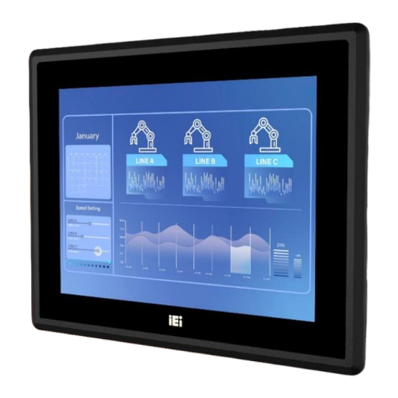
PPC2-xxx-ADLP Panel PC 1.1 Overview Figure 1-1: PPC2-xxx-ADLP Series Panel PC PPC2-xxx-ADLP series is a panel PC powered by 12th Generation Intel® Alder Lake-P Core™ i7/i5/i3 processor with a rich variety of functions and peripherals. The Intel® Alder Lake-P Core™ i7/i5/i3 Processor is a SoC (System-on-Chip) that ensures optimal memory, graphics, and peripheral I/O support. -
Page 17: Model Variations
PPC2-xxx-ADLP Panel PC 1.2 Model Variations The model number and model variation are listed below. Model Size Resolution Processor i3-1220P PPC2-C104-ADLP-i3/8G 800 x 600 10.4” i5-1240P PPC2-C104-ADLP-i5/8G i7-1260P PPC2-C104-ADLP-i7/8G i3-1220P PPC2-C121-ADLP-i3/8G 1024 x 768 12.1” i5-1240P PPC2-C121-ADLP-i5/8G i7-1260P PPC2-C121-ADLP-i7/8G i3-1220P PPC2-CW133-ADLP-i3/8G 1920 x1080 13.3”... -
Page 18: Features
PPC2-xxx-ADLP Panel PC i3-1220P PPC2-C190-ADLP-i3/8G 1280 x 1024 19.0” i5-1240P PPC2-C190-ADLP-i5/8G i7-1260P PPC2-C190-ADLP-i7/8G i3-1220P PPC2-CW215-ADLP-i3/8G 1920 x 1080 21.5” i5-1240P PPC2-CW215-ADLP-i5/8G i7-1260P PPC2-CW215-ADLP-i7/8G Table 1-1: Model Variation 1.3 Features The PPC2-xxx-ADLP Series Panel PC features are listed below: 12th Generation Intel® Alder Lake-P Core™ i7/i5/i3/Celeron® processor ... -
Page 19: Rear Panel
PPC2-xxx-ADLP Panel PC Figure 1-2: Front View 1.5 Rear Panel The rear panel provides access to retention screw holes that support VESA mounting. See Figure 1-3. Figure 1-3: Rear View Page 19... -
Page 20: I/O Panels
PPC2-xxx-ADLP Panel PC 1.6 I/O Panels The I/O Panels of the PPC2-xxx-ADLP Series Panel PC have the following connectors and switches. Figure 1-4: Bottom Panel 1.7 System Specifications The technical specifications for the PPC2-xxx-ADLP Series Panel PC systems are listed in Table 1-2. - Page 21 PPC2-xxx-ADLP Panel PC 8GB on-board dual-channel LPDDR4x RAM Ethernet LAN1: Intel ® I225V 2.5GbE controller LAN2: Intel ® I225-LM 2.5GbE controller (Intel AMT) 1 x M.2 M key 2242 (PCIe Gen4x4) Expansion 1 x M.2 M key 2280 (PCIe Gen4x4) 1 x M.2 E key 2230 (PCIe + USB signal) 2 x 2.5GbE LAN 2 x RS-232/422/485 by DB9...
-
Page 22: Table 1-2: System Specifications
PPC2-xxx-ADLP Panel PC IP Level IP 65 compliant front panel Safety/EMC CE/ EMC, FCC, UKCA Power Requirement 12V DC Thermal Solution Fanless Windows10/11, Linux ErP 2009/125/EC Table 1-2: System Specifications PPC2-C150-ADLP PPC2-CW156-ADLP PPC2-C170-ADLP Model LCD Size 15” (4:3) 15.6” (16:9) 17”... - Page 23 PPC2-xxx-ADLP Panel PC 1 x M.2 M key 2280 (PCIe Gen4x4) 1 x M.2 E key 2230 (PCIe + USB signal) 2 x 2.5GbE LAN 2 x RS-232/422/485 by DB9 2 x RS-232 by DB9 1 x USB 2.0 2 x USB 3.2 Gen 1 I/O Ports 2 x USB 3.2 Gen 2 and Switches...
-
Page 24: Table 1-3: System Specifications
PPC2-xxx-ADLP Panel PC Windows10/11, Linux ErP 2009/125/EC Table 1-3: System Specifications PPC2-CW185-ADLP PPC2-C190-ADLP PPC2-CW215-ADLP Model LCD Size 18.5” (16:9) 19” (5:4) 21.5” (16:9) Resolution 1920 (W) x 1080 (H) 1280 (W) x 1024 (H) 1920 (W) x 1080 (H) Brightness 350 cd/m²... -
Page 25: Table 1-4: System Specifications
PPC2-xxx-ADLP Panel PC Color Silver + Black Operating Temperature -10 ~ 50 ºC (Ambient with air flow) Storage Temperature -20ºC ~ 60 ºC Humidity 10% ~ 95%@40 ºC (non-condensing) IP Level IP 65 compliant front panel Safety/EMC CE/ EMC, FCC, UKCA Power Requirement 12V DC Thermal Solution... -
Page 26: Dimensions
PPC2-xxx-ADLP Panel PC 1.8 Dimensions The PPC2-xxx-ADLP Series Panel PC dimensions are shown below. 1.8.1 PPC2-C104-ADLP Dimensions Figure 1-5: PPC2-C104-ADLP Dimensions (mm) Page 26... -
Page 27: Ppc2-C121-Adlp Dimensions
PPC2-xxx-ADLP Panel PC 1.8.2 PPC2-C121-ADLP Dimensions Figure 1-6: PPC2-C121-ADLP Dimensions (mm) Page 27... -
Page 28: Ppc2-Cw133-Adlp Dimensions
PPC2-xxx-ADLP Panel PC 1.8.3 PPC2-CW133-ADLP Dimensions Figure 1-7: PPC2-CW133-ADLP Dimensions (mm) Page 28... -
Page 29: Ppc2-C150-Adlp Dimensions
PPC2-xxx-ADLP Panel PC 1.8.4 PPC2-C150-ADLP Dimensions Figure 1-8: PPC2-C150-ADLP Dimensions (mm) Page 29... -
Page 30: Sppc2-Cw156-Adlp Dimensions
PPC2-xxx-ADLP Panel PC 1.8.5 sPPC2-CW156-ADLP Dimensions Figure 1-9: PPC2-CW156-ADLP Dimensions (mm) Page 30... -
Page 31: Ppc2-C170-Adlp Dimensions
PPC2-xxx-ADLP Panel PC 1.8.6 PPC2-C170-ADLP Dimensions Figure 1-10: PPC2-C170-ADLP Dimensions (mm) Page 31... -
Page 32: Ppc2-Cw185-Adlp Dimensions
PPC2-xxx-ADLP Panel PC 1.8.7 PPC2-CW185-ADLP Dimensions Figure 1-11: PPC2-CW185-ADLP Dimensions (mm) Page 32... -
Page 33: Ppc2-C190-Adlp Dimensions
PPC2-xxx-ADLP Panel PC 1.8.8 PPC2-C190-ADLP Dimensions Figure 1-12: PPC2-C190-ADLP Dimensions (mm) Page 33... -
Page 34: Ppc2-Cw215-Adlp Dimensions
PPC2-xxx-ADLP Panel PC 1.8.9 PPC2-CW215-ADLP Dimensions Figure 1-13: PPC2-CW215-ADLP Dimensions (mm) Page 34... -
Page 35: Unpacking
PPC2-xxx-ADLP Panel PC Chapter Unpacking Page 35... -
Page 36: Unpacking
PPC2-xxx-ADLP Panel PC 2.1 Unpacking To unpack the panel PC, follow the steps below: WARNING! The front side LCD screen has a protective plastic cover stuck to the screen. Only remove the plastic cover after the panel PC has been properly installed. -
Page 37: Packing List
PPC2-xxx-ADLP Panel PC 2.2 Packing List NOTE: If any of the components listed in the checklist below are missing, do not proceed with the installation. Contact the IEI reseller or vendor the PPC2-xxx- ADLP was purchased from or contact an IEI sales representative directly by sending an email to sales@ieiworld.com. -
Page 38: Optional Items
PPC2-xxx-ADLP Panel PC 2.3 Optional Items The following are optional components which may be separately purchased: Item and Part Number Image VESA 75/100 wall mount kit (P/N: AFLWK-19B) (P/N: ARM-11-RS) Stand for VESA 75/100 (P/N: STAND-C12-R10) LCD monitor stand with adjustable hinge (P/N: VSTAND-A10-R11) Table 2-2: Optional Items If any of these items are missing or damaged, contact the distributor or sales representative... -
Page 39: Installation
PPC2-xxx-ADLP Panel PC Chapter Installation Page 39... -
Page 40: Anti-Static Precautions
PPC2-xxx-ADLP Panel PC 3.1 Anti-static Precautions WARNING: Failure to take ESD precautions during the maintenance of the PPC2- xxx-ADLP may result in permanent damage to the PPC2-xxx-ADLP and severe injury to the user. Electrostatic discharge (ESD) can cause serious damage to electronic components, including the PPC2-xxx-ADLP Series Panel PC. -
Page 41: Installation And Configuration Steps
PPC2-xxx-ADLP Panel PC Anti-static Discharge: If a user opens the rear panel of the panel PC, to configure the jumpers or plug in added peripheral devices, ground themselves first and wear an anti-static wristband. 3.3 Installation and Configuration Steps The following installation steps must be followed. -
Page 42: Module Installation
PPC2-xxx-ADLP Panel PC Figure 3-1: Back Cover Retention Screws Step 2: Slide the back cover toward the I/O panel until it is disengaged from the locking mechanism. Then, lift the back cover off the chassis. See Figure 3-2. Figure 3-2: Remove the Back Cover 3.5 M.2 Module Installation To install a M.2 module into the PPC2-xxx-ADLP, please follow the steps below: Step 1:... -
Page 43: Figure 3-3: M.2 Module Slot Location
PPC2-xxx-ADLP Panel PC Figure 3-3: M.2 Module Slot Location Step 3: Line up the notch on the M.2 module with the notch on the connector. Slide the M.2 module into the socket at an angle of about 20º. Step 4: Secure the M.2 module with the retention screw. -
Page 44: Clear Cmos
PPC2-xxx-ADLP Panel PC 3.6 Clear CMOS If the PPC2-xxx-ADLP fails to boot due to improper BIOS settings, the clear CMOS jumper clears the CMOS data and resets the system BIOS information. To do this, push the clear CMOS button for three seconds, then restart the system. The clear CMOS button location is shown in Figure 3-5. -
Page 45: At Power Mode
PPC2-xxx-ADLP Panel PC 3.7.1 AT Power Mode With the AT mode selected, the power is controlled by a central power unit rather than a power switch. The PPC2-xxx-ADLP panel PC turns on automatically when the power is connected. The AT mode benefits a production line to control multiple panel PCs from a central management center and other applications including: ... -
Page 46: Wall Mounting
PPC2-xxx-ADLP Panel PC 3.8.1 Wall Mounting To mount the panel PC onto the wall, please follow the steps below. Step 1: Select the location on the wall for the wall-mounting bracket. Step 2: Carefully mark the locations of the four screw holes in the bracket on the wall. Step 3: Drill four pilot holes at the marked locations on the wall for the bracket retention screws. - Page 47 PPC2-xxx-ADLP Panel PC WARNING: Please use the M4 screws provided in the wall mount kit for the rear panel. If the screw is missing, the thread depth of the replacement screw should be not more than 4 mm. Step 7: Align the mounting screws on the monitor rear panel with the mounting holes on the bracket.
-
Page 48: Figure 3-8: Chassis Support Screws
PPC2-xxx-ADLP Panel PC Figure 3-8: Chassis Support Screws Step 9: Secure the panel PC by fastening the retention screw of the wall-mounting bracket (Figure 3-9: Secure the Panel PC). Figure 3-9: Secure the Panel PC Page 48... -
Page 49: Arm Mounting
PPC2-xxx-ADLP Panel PC 3.8.2 Arm Mounting The PPC2-xxx-ADLP is VESA (Video Electronics Standards Association) compliant and can be mounted on an arm with a 100 mm interface pad. To mount the PPC2-xxx-ADLP on an arm, please follow the steps below. Step 1: The arm is a separately purchased item. -
Page 50: Stand Mounting
PPC2-xxx-ADLP Panel PC Step 4: Secure the PPC2-xxx-ADLP to the interface pad by inserting four retention screws through the mounting arm interface pad and into the PPC2-xxx-ADLP. Figure 3-11: Arm Mounting 3.8.3 Stand Mounting To mount the PPC2-xxx-ADLP using the stand mounting kit, please follow the steps below. Step 1: Locate the screw holes on the rear of the PPC2-xxx-ADLP. -
Page 51: V-Stand Mounting
PPC2-xxx-ADLP Panel PC Figure 3-12: Stand Mounting (Stand-Cxx) 3.8.4 V-Stand Mounting To mount the PPC2-xxx-ADLP using the optional V-Stand mounting kit, please follow the steps below. Step 1: Carefully mark the locations of the four V-Stand screw holes on the mounting area. -
Page 52: Figure 3-14: Secure V-Stand To System
PPC2-xxx-ADLP Panel PC Step 2: Align the screw holes on the V-Stand with the VESA mount screw holes on the system rear panel. Step 3: Insert the four VESA mount screws into the four screw holes on the system rear panel. -
Page 53: Panel, Rack And Cabinet Installation
PPC2-xxx-ADLP Panel PC 3.8.5 Panel, Rack and Cabinet Installation To mount the PPC2-xxx-ADLP panel PC into a panel, please follow steps 1-5. For rack and cabinet installation, please follow Steps 1-7. NOTE: For the PPC-XXX-ADLP Series panel PC, all mounting kit must be installed (Figure 3-16). -
Page 54: Figure 3-17: Ppc2-C104-Adlp Panel Cutout Dimensions
PPC2-xxx-ADLP Panel PC Figure 3-17: PPC2-C104-ADLP Panel Cutout Dimensions Figure 3-18: PPC2-C121-ADLP Panel Cutout Dimensions Figure 3-19: PPC2-CW133-ADLP Panel Cutout Dimensions Page 54... -
Page 55: Figure 3-20: Ppc2-C150-Adlp Panel Cutout Dimensions
PPC2-xxx-ADLP Panel PC Figure 3-20: PPC2-C150-ADLP Panel Cutout Dimensions Figure 3-21: PPC2-C170-ADLP Panel Cutout Dimensions Figure 3-22: PPC2-C190-ADLP Panel Cutout Dimensions Page 55... -
Page 56: Figure 3-23: Ppc2-Cw156-Adlp Panel Cutout Dimensions
PPC2-xxx-ADLP Panel PC Figure 3-23: PPC2-CW156-ADLP Panel Cutout Dimensions Figure 3-24: PPC2-CW185-ADLP Panel Cutout Dimensions Figure 3-25: PPC2-CW215-ADLP Panel Cutout Dimensions Page 56... -
Page 57: Figure 3-26: Machine Mounted To Panel
PPC2-xxx-ADLP Panel PC Step 7: Slide the PPC2-xxx-ADLP through the hole until the aluminum frame is flush against the panel (Figure 3-26). Figure 3-26: Machine mounted to panel Step 8: Insert the panel mount kit into the prefabricated holes along the rear edge of the PPC2-xxx-ADLP Series (Figure 3-27). -
Page 58: Figure 3-28: Tighten The Mounting Screws
PPC2-xxx-ADLP Panel PC Step 9: Tighten the screws that pass through the mounting clamps until the plastic caps at the front of all the screws are firmly secured to the panel (Figure 3-28). Figure 3-28: Tighten the Mounting Screws Step 10: Slide the PPC2-xxx-ADLP Series with the attached rack/cabinet bracket into a rack or cabinet (Figure 3-29). -
Page 59: Powering On The System
PPC2-xxx-ADLP Panel PC Step 11: Once the flat panel PC with the attached rack/cabinet bracket has been properly inserted into the rack or cabinet, secure the front of the rack/cabinet bracket to the front of the rack or cabinet (Figure 3-29). 3.9 Powering on the System WARNING: To reduce potential safety issues, only the power adapter provided with... -
Page 60: Reset The System
PPC2-xxx-ADLP Panel PC 3.10 Reset the System The reset button enables user to reboot the system when the system is turned on. The reset button location is shown in Figure 3-31. Press the reset button to reboot the system. Figure 3-31: Reset Button Location 3.11 Software Installation All the drivers for the PPC2-xxx-ADLP are available on IEI Resource Download Center (https://download.ieiworld.com). - Page 61 PPC2-xxx-ADLP Panel PC Step 1: Go to https://download.ieiworld.com. Type PPC2-xxx-ADLP and press Enter. Step 2: All product-related software, utilities, and documentation will be listed. You can choose Driver to filter the result. Step 3: Click the driver file name on the page and you will be prompted with the ...
-
Page 62: Adjust Brightlight
PPC2-xxx-ADLP Panel PC NOTE: To install software from the downloaded ISO image file in Windows 8, 8.1 or 10, double-click the ISO file to mount it as a virtual drive to view its content. On Windows 7 system, an additional tool (such as Virtual CD-ROM Control Panel from Microsoft) is needed to mount the file. -
Page 63: System Maintenance
PPC2-xxx-ADLP Panel PC Chapter System Maintenance Page 63... -
Page 64: System Maintenance Introduction
PPC2-xxx-ADLP Panel PC 4.1 System Maintenance Introduction If the components of the PPC2-xxx-ADLP fail they must be replaced. Please contact the system reseller or vendor to purchase the replacement parts. Back cover removal instructions for the PPC2-xxx-ADLP are described below. 4.2 Anti-static Precautions WARNING: Failure to take ESD precautions during the maintenance of the PPC2-... -
Page 65: Turn Off The Power
PPC2-xxx-ADLP Panel PC 4.3 Turn off the Power WARNING: Failing to turn off the system before opening it can cause permanent damage to the system and serious or fatal injury to the user. Before any maintenance procedures are carried out on the system, make sure the system is turned off. -
Page 66: Bios
PPC2-xxx-ADLP Panel PC Chapter BIOS Page 66... -
Page 67: Introduction
PPC2-xxx-ADLP Panel PC 5.1 Introduction The BIOS is programmed onto the BIOS chip. The BIOS setup program allows changes to certain system settings. This chapter outlines the options that can be changed. NOTE: Some of the BIOS options may vary throughout the life cycle of the product and are subject to change without prior notice. -
Page 68: Using Setup
PPC2-xxx-ADLP Panel PC 5.1.2 Using Setup The BIOS Setup menu can be navigated by using a keyboard or a touchscreen. 5.1.2.1 Keyboard Navigation For keyboard navigation, use the navigation keys shown in Table 5-1. Function Up arrow Move to previous item Down arrow Move to next item Left arrow... -
Page 69: Table 5-2: Bios On-Screen Navigation Keys
PPC2-xxx-ADLP Panel PC 5.1.2.2 Touch Navigation For touchscreen navigation, use the on-screen navigation keys shown below. On-screen Button Function Previous Values Load the last value you set. Optimized Defaults Load the factory default values in order to achieve the best performance. Back Return to the previous menu. -
Page 70: Getting Help
PPC2-xxx-ADLP Panel PC 5.1.3 Getting Help When F1 is pressed a small help window describing the appropriate keys to use and the possible selections for the highlighted item appears. To exit the Help Window, press the key. 5.1.4 Unable to Reboot after Configuration Changes If the computer cannot boot after changes to the system configuration is made, CMOS defaults. -
Page 71: Main
PPC2-xxx-ADLP Panel PC 5.2 Main The Main BIOS menu appears when the BIOS Setup program is entered. The Main menu gives an overview of the basic system information. BIOS Menu 1: Main (1/2) BIOS Menu 2: Main (2/2) Page 71... - Page 72 PPC2-xxx-ADLP Panel PC BIOS Information The BIOS Information lists a brief summary of the BIOS. The fields in BIOS Information cannot be changed. The items shown in the system overview include: BIOS Vendor: Installed BIOS vendor Core Version: Current BIOS version ...
-
Page 73: Advanced
PPC2-xxx-ADLP Panel PC System Date [xx/xx/xx]: Use the System Date option to set the system date. Manually enter the day, month and year. System Time [xx:xx:xx]: Use the System Time option to set the system time. Manually enter the hours, minutes and seconds. 5.3 Advanced Use the Advanced menu to configure the CPU and peripheral devices through the following sub-menus:... -
Page 74: Cpu Configuration
PPC2-xxx-ADLP Panel PC Case Open Detection [Disabled] When the Case Open Detection is enabled, if anyone opens the computer's chassis, or case, Windows will notify the user with a pop-up message the next time he turns on his computer. ... - Page 75 PPC2-xxx-ADLP Panel PC BIOS Menu 5: CPU Configuration (2/2) Intel (VMX) Virtualization Technology [Enabled] Use the Intel (VMX) Virtualization Technology option to enable or disable virtualization on the system. When combined with third party software, Intel® Virtualization technology allows several OSs to run on the same system at the same time. ...
- Page 76 PPC2-xxx-ADLP Panel PC Active Efficient-cores [All] Use the Active Efficient-cores BIOS option to enable numbers of Efficient-cores in the processor package. Enable all cores in the processor package. EFAULT Enable one core in the processor package. Enable two cores in the processor package.
- Page 77 PPC2-xxx-ADLP Panel PC Enables CPU to go to C states when it’s not Enabled 100% utilized. Power Limit 1 Use the Power Limit 1 to set Power Limit in Milli Watts. BIOS will round to the nearest 1/8W when programming. 0 = no custom override. For 12.50W, enter 12500. Overclocking SKU: Value must be between Max and Min Power Limits.
-
Page 78: Trusted Computing
PPC2-xxx-ADLP Panel PC 5.3.2 Trusted Computing Use the Trusted Computing menu (BIOS Menu 6) to configure settings related to the Trusted Computing Group (TCG) Trusted Platform Module (TPM). BIOS Menu 6: Trusted Computing Security Device Support [Enable] Use the Security Device Support option to enable or disable BIOS support for security device. -
Page 79: Rtc Wake Setting
PPC2-xxx-ADLP Panel PC 5.3.3 RTC Wake Setting The RTC Wake Settings menu (BIOS Menu 7) configures RTC wake event. BIOS Menu 7: RTC Wake Settings Wake system with Fixed Time [Enabled] Use the Wake system with Fixed Time option to enable or disable the system wake on alarm event. - Page 80 PPC2-xxx-ADLP Panel PC Enabled If selected, the Wake up every day option appears EFAULT allowing you to enable to disable the system to wake every day at the specified time. Besides, the following options appear with values that can be selected: Wake up date Wake up hour Wake up minute...
-
Page 81: F81966 Super Io Configuration
PPC2-xxx-ADLP Panel PC 5.3.4 F81966 Super IO Configuration Use the F81966 Super IO Configuration menu (BIOS Menu 8) to set or change the configurations for serial ports. BIOS Menu 8: F81966 Super IO Configuration Page 81... - Page 82 PPC2-xxx-ADLP Panel PC 5.3.4.1 Serial Port 1 Configuration Use the Serial Port 1 Configuration menu (BIOS Menu 9) to configure the serial port. BIOS Menu 9: Serial Port 1 Configuration Menu Serial Port [Enabled] Use the Serial Port option to enable or disable the serial port. ...
- Page 83 PPC2-xxx-ADLP Panel PC 5.3.4.2 Serial Port 2 Configuration Use the Serial Port 2 Configuration menu (BIOS Menu 10) to configure the serial port. BIOS Menu 10: Serial Port 2 Configuration Menu Serial Port [Enabled] Use the Serial Port option to enable or disable the serial port. ...
- Page 84 PPC2-xxx-ADLP Panel PC 5.3.4.3 Serial Port 3 Configuration Use the Serial Port 3 Configuration menu (BIOS Menu 11) to configure the serial port. BIOS Menu 11: Serial Port 3 Configuration Menu Serial Port [Enabled] Use the Serial Port option to enable or disable the serial port. ...
- Page 85 PPC2-xxx-ADLP Panel PC The serial port mode is RS-232 RS232 EFAULT RS422 with Register The serial port mode is RS-422 RS485 with Register The serial port mode is RS-485 5.3.4.4 Serial Port 4 Configuration Use the Serial Port 4 Configuration menu (BIOS Menu 11) to configure the serial port. BIOS Menu 12: Serial Port 4 Configuration Menu ...
-
Page 86: H/W Monitor
PPC2-xxx-ADLP Panel PC Serial Port I/O port address is 2E8h and the interrupt IO=2E8h; address is IRQ10 IRQ=10 Device Mode [RS232] Use the Device Mode option to change the serial port mode. The serial port mode is RS-232 RS232 EFAULT RS422 with Register... -
Page 87: Serial Port Console Redirection
PPC2-xxx-ADLP Panel PC PC Health Status The following system parameters and values are shown. The system parameters that are monitored are: System Temperatures: CPU Temperature System Temperature1 System Temperature2 CPU_FAN1 Speed: CPU_FAN1 Speed Voltages: +VCCCORE +5VS +12S +V3.3S +VDDQ... - Page 88 PPC2-xxx-ADLP Panel PC BIOS Menu 14: Serial Port Console Redirection (1/2) Page 88...
- Page 89 PPC2-xxx-ADLP Panel PC BIOS Menu 15: Serial Port Console Redirection (2/2) Console Redirection [Disabled] Use Console Redirection option to enable or disable the console redirection function. Disabled Disabled the console redirection function EFAULT Enabled Enabled the console redirection function The Console Redirection Settings submenu will be available when the Console Redirection option is enabled.
- Page 90 PPC2-xxx-ADLP Panel PC BIOS Menu 16: COM Console Redirection Settings Terminal Type [ANSI] Use the Terminal Type option to specify the remote terminal type. VT100 The target terminal type is VT100 The target terminal type is VT100+ VT100+ ...
- Page 91 PPC2-xxx-ADLP Panel PC Sets the serial port transmission speed at 57600. 57600 115200 Sets the serial port transmission speed at 115200. EFAULT Data Bits [8] Use the Data Bits option to specify the number of data bits. ...
-
Page 92: Nvme Configuration
PPC2-xxx-ADLP Panel PC 5.3.7 NVMe Configuration Use the NVMe Configuration (BIOS Menu 17) menu to display the NVMe controller and device information. BIOS Menu 17: NVMe Configuration Page 92... -
Page 93: Chipset
PPC2-xxx-ADLP Panel PC 5.4 Chipset Use the Chipset menu (BIOS Menu 18) to access the PCH IO and System Agent (SA) configuration menus. WARNING! Setting the wrong values for the Chipset BIOS selections in the Chipset BIOS menu may cause the system to malfunction. BIOS Menu 18: Chipset Page 93... -
Page 94: System Agent (Sa) Configuration
PPC2-xxx-ADLP Panel PC 5.4.1 System Agent (SA) Configuration Use the System Agent (SA) Configuration menu to configure the System Agent (SA) parameters. BIOS Menu 19: System Agent (SA) Configuration VT-d [Enabled] Use the VT-d option to enable or disable the VT-d capability. ... - Page 95 PPC2-xxx-ADLP Panel PC 5.4.1.1 Memory Configuration Use the Memory Configuration submenu (BIOS Menu 20) to view memory information. BIOS Menu 20: Memory Configuration Page 95...
- Page 96 PPC2-xxx-ADLP Panel PC 5.4.1.2 Graphics Configuration Use the Graphics Configuration (BIOS Menu 21) menu to configure the video device connected to the system. BIOS Menu 21: Graphics Configuration Page 96...
- Page 97 PPC2-xxx-ADLP Panel PC 5.4.1.3 VMD Configuration BIOS Menu 22: VMD Configuration Enable VMD Controller [Enabled] Enable/Disable to VMD controller. Disabled Disable the VMD controller Enabled Enable the VMD controller EFAULT Page 97...
- Page 98 PPC2-xxx-ADLP Panel PC 5.4.1.4 PEG Configuration Use the PEG Configuration (BIOS Menu 23) menu to configure the M2_M1 slot and the M2_M2 slot. BIOS Menu 23: PEG Configuration Detect Non-Compliance Device [Disabled] Use the Detect Non-Compliance Device option to configure whether to detect if a non- compliance PCI Express device is connected to the PCI Express port.
- Page 99 PPC2-xxx-ADLP Panel PC BIOS Menu 24: M2_M1 M2_M1 [Enabled] Use the M2_M1 to Control the PEG Root Port. Disabled Disable the M2_M1 Enable the M2_M1 Enabled EFAULT PCIe Speed [Auto] Use the PCIe Speed option to specify the PCI Express port speed. Configuration options are listed below.
- Page 100 PPC2-xxx-ADLP Panel PC Configure PCIe Speed to Gen4. Gen4 Gen5 Configure PCIe Speed to Gen5. 5.4.1.4.2 M2_M2 Use the M2_M2 menu (BIOS Menu 25) to change and/or set the configuration of the M2_M2 devices installed in the system. BIOS Menu 25: M2_M2 ...
- Page 101 PPC2-xxx-ADLP Panel PC Configure PCIe Speed to Gen1. Gen1 Gen2 Configure PCIe Speed to Gen2. Gen3 Configure PCIe Speed to Gen3. Gen4 Configure PCIe Speed to Gen4. Configure PCIe Speed to Gen5. Gen5 Page 101...
-
Page 102: Pch-Io Configuration
PPC2-xxx-ADLP Panel PC 5.4.2 PCH-IO Configuration Use the PCH-IO Configuration menu (BIOS Menu 26) to configure the PCH parameters. BIOS Menu 26: PCH-IO Configuration(1/2) Page 102... - Page 103 PPC2-xxx-ADLP Panel PC BIOS Menu 27: PCH-IO Configuration (2/2) Auto Power Button Function [Disabled (AT)] Use the Auto Power Button Function BIOS option to show the power mode state. Use the J_ATX_AT1 to switch the AT/ATX power mode. Enabled (AT) The system power mode is AT.
- Page 104 PPC2-xxx-ADLP Panel PC Power Saving Function (EUP) [Disabled] Use the Power Saving Function (EUP) BIOS option to enable or disable the power saving function. Disabled Power saving function is disabled. EFAULT Power saving function is enabled. It will reduce power Enabled consumption when the system is off.
- Page 105 PPC2-xxx-ADLP Panel PC Sets the USB power source to +5V dual +5V DUAL EFAULT Sets the USB power source to +5V 5.4.2.1 PCI Express Configuration Use the PCI Express Configuration submenu (BIOS Menu 28) to configure the PCI Express slots.
- Page 106 PPC2-xxx-ADLP Panel PC BIOS Menu 29: M2_E1 PCIe Speed [Auto] Use the PCIe Speed option to specify the PCI Express port speed. Configuration options are listed below. Auto Auto mode. EFAULT Gen1 Configure PCIe Speed to Gen1. ...
- Page 107 PPC2-xxx-ADLP Panel PC Detect if a non-compliance PCI Express device is Enabled connected to the PCI Express port. 5.4.2.2 HD Audio Configuration Use the HD Audio Configuration menu (BIOS Menu 30) to configure the PCH Azalia settings. BIOS Menu 30: HD Audio Configuration ...
-
Page 108: Security
PPC2-xxx-ADLP Panel PC The onboard High Definition Audio controller is enabled. Enabled EFAULT 5.5 Security Use the Security menu (BIOS Menu 31) to set system and user passwords. BIOS Menu 31: Security (1/2) Page 108... - Page 109 PPC2-xxx-ADLP Panel PC BIOS Menu 32: Security (2/2) Administrator Password Use the Administrator Password to set or change an administrator password. User Password Use the User Password to set or change a user password. Page 109...
-
Page 110: Boot
PPC2-xxx-ADLP Panel PC 5.6 Boot Use the Boot menu (BIOS Menu 33) to configure system boot options. BIOS Menu 33: Boot 5.6.1 Boot Configuration Quiet Boot [Enabled] Use the Quiet Boot BIOS option to select the screen display when the system boots. ... -
Page 111: Boot Option Priorities
PPC2-xxx-ADLP Panel PC Enable the lan pxe Enabled 5.6.2 Boot Option Priorities Use the Boot Option # N to choose the system boots from the peripherals you selected. The following Boot Options are listed as an example. Boot Option #1 Sets the system boot order ADATA SP580 as the first priority. -
Page 112: Save & Exit
PPC2-xxx-ADLP Panel PC 5.7 Save & Exit Use the Save & Exit menu (BIOS Menu 34) to load default BIOS values, optimal failsafe values and to save configuration changes. BIOS Menu 34: Save & Exit Save Changes and Reset Use the Save Changes and Reset option to save the changes made to the BIOS options and reset the system. - Page 113 PPC2-xxx-ADLP Panel PC Save as User Defaults Use the Save as User Defaults option to save the changes done so far as user defaults. Restore User Defaults Use the Restore User Defaults option to restore the user defaults to all the setup options. Page 113...
-
Page 114: Interface Connectors
PPC2-xxx-ADLP Panel PC Chapter Interface Connectors Page 114... -
Page 115: Peripheral Interface Connectors
PPC2-xxx-ADLP Panel PC 6.1 Peripheral Interface Connectors The PPC2-xxx-ADLP panel PC motherboard comes with a number of peripheral interface connectors and configuration jumpers. The connector locations are shown in Figure 6-1 and Figure 6-2. The Pin 1 locations of the on-board connectors are also indicated in the diagram below. -
Page 116: Internal Peripheral Connectors
PPC2-xxx-ADLP Panel PC Figure 6-2: Main Board Layout Diagram (Solder Side) 6.2 Internal Peripheral Connectors Internal peripheral connectors are found on the motherboard and are only accessible when the motherboard is outside of the chassis. The table below shows a list of the peripheral interface connectors on the PPC2-xxx-ADLP Series Panel PC motherboard. -
Page 117: Touch Panel Connector (J_Touch1)
PPC2-xxx-ADLP Panel PC Connector Type Label M.2 M-Key Slot M-key slot M2_M2 eDP Connector 40-pin connector EDP1 LVDS Panel Connector 30-pin connector LVDS1 5-pin connector LVDS Backlight Power INV1 CPU Fan Connector 4-pin wafer CPU_FAN1 3-pin header MPS PWM IC Programmer Connector Flash Descriptor Security Override 2-pin header ME_FLASH1... -
Page 118: For Ec Debug Connector (Ec_Dbg1)
PPC2-xxx-ADLP Panel PC 6.2.3 For EC Debug Connector (EC_DBG1) PIN NO. DESCRIPTION EDICS EDIDO EDICLK EDIDI Table 6-4: For EC Debug Connector (EC_DBG1) Pinouts 6.2.4 EC Programmer Connector (EC_SPI1) PIN NO. DESCRIPTION PIN NO. DESCRIPTION VCC3.3V MISO HOLD DET# MOSI Table 6-5: EC Programmer Connector (EC_SPI1) Pinouts 6.2.5 Speaker Connector (SPK1) PIN NO. -
Page 119: Digital Mic Connector (Dmic1)
PPC2-xxx-ADLP Panel PC 6.2.7 Digital MIC Connector (DMIC1) DESCRIPTION DMIC_CLK DMIC_DATA VCC3.3V Table 6-8: Digital MIC Connector (DMIC1) Pinouts 6.2.8 CMOS Battery Header (BAT1) PIN NO. DESCRIPTION VBAT+ Table 6-9: CMOS Battery Header (BAT1) Pinouts 6.2.9 M.2 A-Key Slot (M2_AE1) PIN NO. -
Page 120: M-Key Slot (M2_M1)
PPC2-xxx-ADLP Panel PC PIN NO. DESCRIPTION PIN NO. DESCRIPTION PETP0 PETN0 PERP0 PERN0 PCIE_CLK+ PCIE_CLK- PLT_RST CLKREQ0# Pull up PCIE_WAKE W_DIS I2C_DAT I2C_CLK +3.3V +3.3V +3.3V Table 6-10: M.2 A-Key Slot (M2_AE1) Pinouts 6.2.10 M.2 M-Key Slot (M2_M1) PIN NO. DESCRIPTION PIN NO. - Page 121 PPC2-xxx-ADLP Panel PC PIN NO. DESCRIPTION PIN NO. DESCRIPTION PERP3 DAS/DSS# PETN3 +3.3V PETP3 +3.3V +3.3V PERN2 +3.3V PERP2 PETN2 PETP2 PERN1 PERP1 PETN1 PETP1 DEVSLP PERN0 PERP0 PETN0 PETP0 PERST# CLKREQ PCIECLKN PEWAKE PCIECLKP PEDET +3.3V Page 121...
-
Page 122: M-Key Slot (M2_M2)
PPC2-xxx-ADLP Panel PC PIN NO. DESCRIPTION PIN NO. DESCRIPTION +3.3V +3.3V +3.3V Table 6-11: M.2 M-Key Slot (M2_M1) Pinouts 6.2.11 M.2 M-Key Slot (M2_M2) PIN NO. DESCRIPTION PIN NO. DESCRIPTION +3.3V +3.3V PERN3 PERP3 DAS/DSS# PETN3 +3.3V PETP3 +3.3V +3.3V PERN2 +3.3V PERP2... -
Page 123: Edp Connector (Edp1)
PPC2-xxx-ADLP Panel PC PIN NO. DESCRIPTION PIN NO. DESCRIPTION CLKREQ PCIECLKN PEWAKE PCIECLKP Table 6-12: M.2 M-Key Slot (M2_M2) Pinouts 6.2.12 eDP Connector (EDP1) PIN NO. DESCRIPTION PIN NO. DESCRIPTION +VCC_LCD LANE3_N DET_N LANE3_P LANE2_N LANE2_P LANE1_N LANE1_P LANE0_N BKLT_EN LANE0_P BKLT_PWM AUX_P... -
Page 124: Lvds Panel Connector (Lvds1)
PPC2-xxx-ADLP Panel PC 6.2.13 LVDS Panel Connector (LVDS1) PIN NO. DESCRIPTION PIN NO. DESCRIPTION CLK1P CLK1N CLK2P CLK2N DET_N (GND) +VCC_LCD +VCC_LCD +VCC_LCD +VCC_LCD Table 6-14: LVDS Panel Connector (LVDS1) Pinouts 6.2.14 LVDS Backlight Power (INV1) PIN NO. DESCRIPTION BKLT_PWM VCC12V ON/OFF Table 6-15: LVDS Backlight Power (INV1) Pinouts... -
Page 125: Mps Pwm Ic Programmer Connector (J1)
PPC2-xxx-ADLP Panel PC VCC12V FANIO Table 6-16: CPU Fan Connector (CPU_FAN1) Pinouts 6.2.16 MPS PWM IC Programmer Connector (J1) PIN NO. DESCRIPTION Table 6-17: MPS PWM IC Programmer Connector (J1) 6.2.17 Flash Descriptor Security Override (ME_FLASH1) PIN NO. DESCRIPTION Table 6-18: Flash Descriptor Security Override (ME_FLASH1) 6.2.18 Chassis Pin Header (J_CHASSIS1) PIN NO. -
Page 126: Jumper Less Setting
PPC2-xxx-ADLP Panel PC 6.3 Jumper less Setting Type Jumper LABEL PWM Power Selection 3-pin header J_PWM1 Backlight Enable Power Selection 3-pin header J_BL_EN Backlight VCC Selection 3-pin header J_BL_VCC LVDS Power Selection 3-pin header J_VLVDS Flash Mode Header 3-pin header J_FLASH1 Table 6-21: Jumper less Setting 6.3.1 Panel +VCC_LCD Power Setting (J_PW1) -
Page 127: Lvds Power Selection (J_Vlvds1)
PPC2-xxx-ADLP Panel PC 6.3.4 LVDS Power Selection (J_VLVDS1) J_VLVDS1 DESCRIPTION +3.3V(Default) Table 6-25: LVDS Power Selection (J_VLVDS1) 6.3.5 Flash Descriptor Security Override J_FLASH1 DESCRIPTION 1-2(default)* Disabled-Default Short 2-3 Enabled Table 6-26: Flash Descriptor Security Override 6.4 External Interface Panel Connectors This chapter describes how to connect peripherals, switches and indicators to the AFL4- W101/W121/12/W133-ADLP-MB V1.00 board. -
Page 128: Rs-232/422/485 Serial Ports (Com1/2/3/4)
PPC2-xxx-ADLP Panel PC 6.4.1 RS-232/422/485 Serial Ports (COM1/2/3/4) PIN NO. DESCRIPTION DATA CARRIER DETECT (DCD) RECEIVE DATA (RXD) TRANSMIT DATA (TXD) DATA TERMINAL READY (DTR) GND (GND) DATA SET READY (DSR) REQUEST TO SEND (RTS1/2) CLEAR TO SEND (CTS1/2) RING INDICATOR (RI1/2) Table 6-28: External Serial Port Connector (COM1/2/3/4) Pinouts 6.4.2 RJ45 LAN Connector (LAN1/2) PIN NO. -
Page 129: Usb 2.0 Connectors (Usb5)
PPC2-xxx-ADLP Panel PC PIN NO. DESCRIPTION PIN NO. DESCRIPTION HDMI_GND HDMI_DATA0# HDMI_GND HDMI_CLK HDMI_GND HDMI_GND HDMI_CLK# HDMI_GND Table 6-30: HDMI1 Connector (HDMI1) Pinouts 6.4.4 USB 2.0 Connectors (USB5) PIN NO. DESCRIPTION USB_PN- USB_PP+ Table 6-31: USB 2.0 Connectors (USB5) Pinouts 6.4.5 USB 3.2 Gen 1 Connectors (USB3/4) PIN NO. -
Page 130: Usb 3.2 Gen 2 Connectors (Usb1)
PPC2-xxx-ADLP Panel PC 6.4.6 USB 3.2 Gen 2 Connectors (USB1) PIN NO. DESCRIPTION USB_PN- USB_PP+ USB3_RX_N USB3_RX_P USB3_TX_N USB3_TX_P Table 6-33: USB 3.2 Gen 2 Connectors (USB1) Pinouts 6.4.7 Power Button (PWR_SW1) PIN NO. DESCRIPTION PIN NO. DESCRIPTION Table 6-34: Power Button (PWR_SW1) Pinouts 6.4.8 DC Jack PIN NO. - Page 131 PPC2-xxx-ADLP Panel PC Appendix Regulatory Compliance Page 131...
- Page 132 PPC2-xxx-ADLP Panel PC DECLARATION OF CONFORMITY This equipment is in conformity with the following EU directives: EMC Directive (2014/30/EU) Low-Voltage Directive (2014/35/EU) RoHS II Directive (2015/863/EU) If the user modifies and install other devices in the equipment, the CE conformity declaration may no longer apply.
- Page 133 PPC2-xxx-ADLP Panel PC Česky [Czech] IEI Integration Corp tímto prohlašuje, že tento zařízení je ve shodě se základními požadavky a dalšími příslušnými ustanoveními směrnice 2014/53/EU. Dansk [Danish] IEI Integration Corp erklærer herved, at følgende udstyr overholder de væsentlige krav og øvrige relevante krav i direktiv 2014/53/EU.
- Page 134 PPC2-xxx-ADLP Panel PC Malti [Maltese] IEI Integration Corp jiddikjara li dan prodott jikkonforma mal-ħtiġijiet essenzjali u ma provvedimenti oħrajn relevanti li hemm fid-Dirrettiva 2014/53/EU. Magyar [Hungarian] IEI Integration Corp nyilatkozom, hogy a berendezés megfelel a vonatkozó alapvetõ követelményeknek és az 2014/53/EU irányelv egyéb elõírásainak. Polski [Polish] IEI Integration Corp oświadcza, że wyrobu jest zgodny z zasadniczymi wymogami oraz pozostałymi stosownymi postanowieniami Dyrektywy 2014/53/EU.
- Page 135 PPC2-xxx-ADLP Panel PC ROHS STATEMENT The label on the product indicates this product conforms to European (EU) Restriction of Hazardous Substances (RoHS) that set maximum concentration limits on hazardous materials used in electrical and electronic equipment. UKCA WARNING Hereby, IEI INTEGRATION CORP declares that the radio equipment type AFL4-W101- ADLP 、AFL4-W121-ADLP、AFL4-12-ADLP、AFL4-W133-ADLP are in compliance with the Radio Equipment Regulations 2017(S.I.
- Page 136 PPC2-xxx-ADLP Panel PC FCC WARNING This equipment complies with Part 15 of the FCC Rules. Operation is subject to the following two conditions: This device may not cause harmful interference, and This device must accept any interference received, including interference ...
- Page 137 PPC2-xxx-ADLP Panel PC Appendix Safety Precautions Page 137...
- Page 138 PPC2-xxx-ADLP Panel PC WARNING: The precautions outlined in this chapter should be strictly followed. Failure to follow these precautions may result in permanent damage to the PPC2-xxx-ADLP. B.1 Safety Precautions Please follow the safety precautions outlined in the sections that follow: B.1.1 General Safety Precautions Please ensure the following safety precautions are adhered to at all times.
- Page 139 PPC2-xxx-ADLP Panel PC If considerable amounts of dust, water, or fluids enter the device, turn off the power supply immediately, unplug the power cord, and contact the PPC2-xxx-ADLP vendor. RTC battery safety precautions: RISK OF EXPLOSION IF BATTERY IS REPLACED BY AN INCORRECT TYPE Disposal of a battery into fire or a hot oven, or mechanically crushing or cutting of a battery, that can result in an explosion...
- Page 140 PPC2-xxx-ADLP Panel PC Self-grounding: Before handling any electrical component, touch any grounded conducting material. During the time the electrical component is handled, frequently touch any conducting materials that are connected to the ground. Use an anti-static pad: When configuring or working with an electrical component, place it on an anti-static pad.
- Page 141 PPC2-xxx-ADLP Panel PC the shop where you purchased the product. The mark on electrical and electronic products only applies to the current European Union Member States. Please follow the national guidelines for electrical and electronic product disposal. B.2 Maintenance and Cleaning Precautions When maintaining or cleaning the PPC2-xxx-ADLP, please follow the guidelines below.
- Page 142 PPC2-xxx-ADLP Panel PC B.2.2 Cleaning Tools Some components in the PPC2-xxx-ADLP may only be cleaned using a product specifically designed for the purpose. In such case, the product will be explicitly mentioned in the cleaning tips. Below is a list of items to use when cleaning the PPC2-xxx-ADLP. ...
- Page 143 PPC2-xxx-ADLP Panel PC Appendix Watchdog Timer Page 143...
- Page 144 PPC2-xxx-ADLP Panel PC NOTE: The following discussion applies to DOS. Contact IEI support or visit the IEI website for drivers for other operating systems. The Watchdog Timer is a hardware-based timer that attempts to restart the system when it stops working. The system may stop working because of external EMI or software bugs. The Watchdog Timer ensures that standalone systems like ATMs will automatically attempt to restart in the case of system problems.
- Page 145 PPC2-xxx-ADLP Panel PC NOTE: The Watchdog Timer is activated through software. The software application that activates the Watchdog Timer must also deactivate it when closed. If the Watchdog Timer is not deactivated, the system will automatically restart after the Timer has finished its countdown. EXAMPLE PROGRAM: ;...
- Page 146 PPC2-xxx-ADLP Panel PC Appendix Hazardous Materials Disclosure Page 146...
- Page 147 PPC2-xxx-ADLP Panel PC D.1.1 RoHS II Directive (2015/863/EU) The details provided in this appendix are to ensure that the product is compliant with the RoHS II Directive (2015/863/EU). The table below acknowledges the presences of small quantities of certain substances in the product, and is applicable to RoHS II Directive (2015/863/EU).
- Page 148 PPC2-xxx-ADLP Panel PC D.1.2 China RoHS 此附件旨在确保本产品符合中国 RoHS 标准。以下表格标示此产品中某有毒物质的含量符 合中国 RoHS 标准规定的限量要求。 本产品上会附有”环境友好使用期限”的标签,此期限是估算这些物质”不会有泄漏或突变”的 年限。本产品可能包含有较短的环境友好使用期限的可替换元件,像是电池或灯管,这些元 件将会单独标示出来。 部件名称 有毒有害物质或元素 壳体 印刷电路板 金属螺帽 电缆组装 风扇组装 电力供应组装 电池 O: 表示该有毒有害物质在该部件所有物质材料中的含量均在 SJ/T11364-2014 與 GB/T26572- 2011 标准规定的限量要求以下。 X: 表示该有毒有害物质至少在该部件的某一均质材料中的含量超出 SJ/T11364-2014 與 GB/T26572-2011 标准规定的限量要求。 Page 148...
Need help?
Do you have a question about the PPC2 ADLP Series PPC2-C104-ADLP-i3/8G and is the answer not in the manual?
Questions and answers