Table of Contents
Advertisement
Quick Links
Advertisement
Chapters
Table of Contents

Related Manuals for IEI Technology PPC-F D-ULT5 Series


Summary of Contents for IEI Technology PPC-F D-ULT5 Series
- Page 1 PPC-FxxD-ULT5 ePPC-FxxD-ULT5 Panel PC MODEL: MODEL: PPC-FxxD-ULT5 Modular Panel PC with 8 Gen. Intel® Core™ i5-8365UE / Celeron® 4305UE CPU, DDR4, HDMI, USB 3.2 Gen 2, Triple GbE, RS-232/422/485, M.2 M-key/A-key, PoE, IP66 and RoHS Compliant User Manual Page i Rev.
- Page 2 PPC-FxxD-ULT5 Revision Date Version Changes December 1, 2020 1.00 Initial release Page ii...
- Page 3 PPC-FxxD-ULT5 Safety Instructions Warning! Read the user manual before connecting the system to the power source. Vorsicht! Bitte lesen Sie die Bedienungsanleitung, bevor Sie das System an eine Stromquelle anschließen. Attention! Avant de brancher le système à la source d'alimentation, consultez le mode d'emploi.
- Page 4 PPC-FxxD-ULT5 Warning! Ultimate disposal of this product should be handled according to all national laws and regulations. Vorsicht! Die Entsorgung dieses Produkts sollte gemäß allen Bestimmungen und Gesetzen des Landes erfolgen. Attention! La mise au rebut ou le recyclage de ce produit sont généralement soumis aux lois et/ou directives de respect de l'environnement.
- Page 5 PPC-FxxD-ULT5 Copyright COPYRIGHT NOTICE The information in this document is subject to change without prior notice in order to improve reliability, design and function and does not represent a commitment on the part of the manufacturer. In no event will the manufacturer be liable for direct, indirect, special, incidental, or consequential damages arising out of the use or inability to use the product or documentation, even if advised of the possibility of such damages.
- Page 6 PPC-FxxD-ULT5 Manual Conventions WARNING Warnings appear where overlooked details may cause damage to the equipment or result in personal injury. Warnings should be taken seriously. CAUTION Cautionary messages should be heeded to help reduce the chance of losing data or damaging the product. NOTE These messages inform the reader of essential but non-critical information.
-
Page 7: Table Of Contents
PPC-FxxD-ULT5 Table of Contents 1 INTRODUCTION ......................1 1.1 O ........................2 VERVIEW 1.2 M ....................3 ODEL ARIATIONS 1.3 F ........................3 EATURES 1.4 F ......................4 RONT ANEL 1.5 B ......................4 OTTOM ANEL 1.6 R ....................... 5 ANEL 1.7 T .................. - Page 8 PPC-FxxD-ULT5 3.8.2 Panel Mounting ....................31 3.8.3 Rack and Cabinet Installation ................. 34 3.8.4 Wall Mounting ....................36 3.9 RS-232/422/485 S (COM1) S ..........38 ERIAL ELECTION 3.9.1 COM1 Pinouts ....................38 3.9.2 COM1 Pin 9 Selection ..................39 3.10 C CMOS ......................
- Page 9 PPC-FxxD-ULT5 4.3.9 USB Configuration ................... 64 4.3.10 CSM Configuration ..................65 4.3.11 NVMe Configuration ..................66 4.3.12 IEI Feature ..................... 67 4.4 C ........................68 HIPSET 4.4.1 System Agent (SA) Configuration ..............68 4.4.1.1 Memory Configuration ................69 4.4.1.2 Graphics Configuration ................70 4.4.2 PCH-IO Configuration ..................
- Page 10 PPC-FxxD-ULT5 5.3.5 RS-232 RJ-45 Serial Port (COM2) ..............91 5.3.6 USB 3.2 Gen 2 Connectors (USB_CON1, USB_CON2) ......... 92 5.4 J ........................92 UMPERS 5.4.1 Flash Descriptor Security Override Jumper ............ 92 A REGULATORY COMPLIANCE ................94 B SAFETY PRECAUTIONS ..................99 B.1 S ...................
- Page 11 PPC-FxxD-ULT5 List of Figures Figure 1-1: PPC-FxxD-ULT5 Series Panel PC ................2 Figure 1-2: Front Panel ........................4 Figure 1-3: Bottom Panel ....................... 4 Figure 1-4: Rear Panel ........................5 Figure 1-5: PPC-F15D-ULT5 Dimensions (Unit: mm) ..............10 Figure 1-6: PPC-FW15D-ULT5 Dimensions (Unit: mm) ............. 11 Figure 1-7: PPC-F17D-ULT5 Dimensions (Unit: mm) ..............
- Page 12 PPC-FxxD-ULT5 Figure 3-24: Tighten the Mounting Clamp Screws ..............33 Figure 3-25: The Rack/Cabinet Bracket ..................34 Figure 3-26: Secure the Rack/Cabinet Bracket ................35 Figure 3-27: Install into a Rack/Cabinet ..................35 Figure 3-28: Wall-mounting Bracket ................... 36 Figure 3-29: Mount the Chassis ....................37 Figure 3-30: Secure the Chassis ....................
- Page 13 PPC-FxxD-ULT5 List of Tables Table 1-1: Model Variations ......................3 Table 1-2: Technical Specifications (15" & 15.6") ............... 7 Table 1-3: Technical Specifications (17" & 18.5") ............... 9 Table 2-1: Package List ........................ 16 Table 2-2: Optional Items ......................16 Table 3-1: RS-232/422/485 Serial Port (COM1) Pinouts ............
- Page 14 PPC-FxxD-ULT5 List of BIOS Menus BIOS Menu 1: Main ........................48 BIOS Menu 2: Advanced ......................49 BIOS Menu 3: CPU Configuration ....................50 BIOS Menu 4: PCH-FW Configuration ..................52 BIOS Menu 5: PTT Configuration ....................53 BIOS Menu 6: Trusted Computing ....................54 BIOS Menu 7: ACPI Settings .......................
-
Page 15: Introduction
PPC-FxxD-ULT5 Chapter Introduction Page 1... -
Page 16: Overview
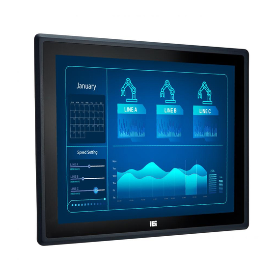
PPC-FxxD-ULT5 1.1 Overview Figure 1-1: PPC-FxxD-ULT5 Series Panel PC ® ® The PPC-FxxD-ULT5 series is a quad-core Intel Core™ i5-8365UE / Celeron 4305UE powered flat bezel touchscreen panel PC with a rich variety of functions and peripherals. It has a unique modular design to achieve high flexibility by assembling the FLEX series system with the LCD touchscreen module. -
Page 17: Model Variations
PPC-FxxD-ULT5 1.2 Model Variations The model variations of the PPC-FxxD-ULT5 panel PC series are listed below. Size Resolutions Processor + Memory PPC-F15D-ULT5-i5/4G/PC 15" 1024x768 PPC-FW15D-ULT5-i5/4G/PC 15.6" 1366x768 ® Intel Core™ i5-8365UE CPU PPC-F17D-ULT5-i5/4G/PC 17" 1280x1024 4 GB DDR4 SO-DIMM PPC-FW19D-ULT5-i5/4G/PC 18.5"... -
Page 18: Front Panel
PPC-FxxD-ULT5 1.4 Front Panel The front side of the PPC-FxxD-ULT5 is a flat panel LCD with P-CAP touchscreen surrounded by a metal frame. Figure 1-2: Front Panel 1.5 Bottom Panel An overview of the bottom panel is shown below. Figure 1-3: Bottom Panel Page 4... -
Page 19: Rear Panel
PPC-FxxD-ULT5 1.6 Rear Panel The rear panel has retention screw holes that support VESA mounting. The rear panel also provides access to the HDD bay and the PoE card slots. Figure 1-4: Rear Panel Page 5... -
Page 20: Technical Specifications
PPC-FxxD-ULT5 1.7 Technical Specifications 1.7.1 15" & 15.6" Specifications PPC-F15D-ULT5 PPC-FW15D-ULT5 LCD Size 15" 15.6" Max. Resolution 1024 x 768 1366 x 768 Brightness (cd/m²) Contrast Ratio 800:1 500:1 LCD Color 16.2M 16.2M Pixel Pitch (mm) 0.29 x 0.29 0.252 x 0.252 Viewing Angle (H/V) 160°/150°... -
Page 21: Table 1-2: Technical Specifications (15" & 15.6")
PPC-FxxD-ULT5 4 x USB 3.2 Gen 2 (10 Gb/s) Type-A Realtek ALC888 HD codec Audio 1 x Line-out jack Display Output 1 x HDMI Expansion 1 x M.2 A-key (2230, PCIe x2 / USB 2.0 / I C), supports Wi-Fi + BT module 1 x Power button with LED indicator Buttons and 1 x Reset button... -
Page 22: 17" & 18.5" Specifications
PPC-FxxD-ULT5 1.7.2 17" & 18.5" Specifications PPC-F17D-ULT5 PPC-FW19D-ULT5 LCD Size 17" 18.5" Max. Resolution 1280 x 1024 1366 x 768 Brightness (cd/m²) Contrast Ratio 1000:1 1000:1 LCD Color 16.7M 16.7M Pixel Pitch (mm) 0.26 x 0.26 0.3 x 0.3 Viewing Angle (H/V) 170°/160°... -
Page 23: Table 1-3: Technical Specifications (17" & 18.5")
PPC-FxxD-ULT5 Realtek ALC888 HD codec Audio 1 x Line-out jack Display Output 1 x HDMI Expansions 1 x M.2 A-key (2230, PCIe x2 / USB 2.0 / I C), supports Wi-Fi + BT module 1 x Power button with LED indicator Buttons and 1 x Reset button Indicators... -
Page 24: Dimensions
PPC-FxxD-ULT5 1.8 Dimensions 1.8.1 PPC-F15D-ULT5 Dimensions Figure 1-5: PPC-F15D-ULT5 Dimensions (Unit: mm) Page 10... -
Page 25: Ppc-Fw15D-Ult5 Dimensions
PPC-FxxD-ULT5 1.8.2 PPC-FW15D-ULT5 Dimensions Figure 1-6: PPC-FW15D-ULT5 Dimensions (Unit: mm) Page 11... -
Page 26: Ppc-F17D-Ult5 Dimensions
PPC-FxxD-ULT5 1.8.3 PPC-F17D-ULT5 Dimensions Figure 1-7: PPC-F17D-ULT5 Dimensions (Unit: mm) Page 12... -
Page 27: Ppc-Fw19D-Ult5 Dimensions
PPC-FxxD-ULT5 1.8.4 PPC-FW19D-ULT5 Dimensions Figure 1-8: PPC-FW19D-ULT5 Dimensions (Unit: mm) Page 13... -
Page 28: Unpacking
PPC-FxxD-ULT5 Chapter Unpacking Page 14... -
Page 29: Unpacking
PPC-FxxD-ULT5 2.1 Unpacking To unpack the panel PC, follow the steps below: Step 1: Use box cutters, a knife or a sharp pair of scissors that seals the top side of the external (second) box. Step 2: Open the external (second) box. Step 3: Use box cutters, a knife or a sharp pair of scissors that seals the top side of the internal (first) box. -
Page 30: Optional Items
PPC-FxxD-ULT5 96 W power adapter Power cord Screws (M4*8) for VESA mounting Screws (M3*4) for HDD installation Backup screws (M4*4) for rear panel installation Table 2-1: Package List 2.3 Optional Items The following items are optional accessories for the PPC-FxxD-ULT5 series: Item PPC-F15D PPC-FW15D... -
Page 31: Installation
PPC-FxxD-ULT5 Chapter Installation Page 17... -
Page 32: Anti-Static Precautions
PPC-FxxD-ULT5 3.1 Anti-static Precautions WARNING: Failure to take ESD precautions during the maintenance of the PPC-FxxD-ULT5 may result in permanent damage to the PPC-FxxD-ULT5 and severe injury to the user. Electrostatic discharge (ESD) can cause serious damage to electronic components, including the WAFER series motherboard and the power module. -
Page 33: Installation Procedure
PPC-FxxD-ULT5 may only be carried out by qualified personnel who are familiar with the associated dangers. Never open the equipment. For safety reasons, the equipment should be opened only by qualified skilled person. Air Circulation: Make sure there is sufficient air circulation when installing the PPC-FxxD-ULT5. -
Page 34: Hdd Installation
PPC-FxxD-ULT5 3.4 HDD Installation To install the HDD into the system, please follow the steps below: Step 1: Remove the HDD cover retention screws located on the left side of the rear panel. Slide the cover upwards to remove it. Figure 3-1: HDD Cover Retention Screws Step 2: Remove the four HDD bracket retention screws and lift the HDD bracket off the... -
Page 35: Figure 3-3: Hdd Retention Screws
PPC-FxxD-ULT5 Step 3: Attach the HDD brackets to the HDD. To do this, align the four retention screw holes in the both sides of the HDD bracket with the retention screw holes on the sides of the HDD. Insert four retention screws into the HDD bracket (Figure 3-3). -
Page 36: Poe Pd Module Installation (Optional)
PPC-FxxD-ULT5 3.5 PoE PD Module Installation (Optional) An IEI PoE module must be installed before start using the panel PC as a PoE powered device (PD). To install the optional PoE module, follow the steps below. Step 1: Remove the PoE card cover retention screws located on the right side of the rear panel. -
Page 37: Ssd Installation (Optional)
PPC-FxxD-ULT5 Step 3: Remove the on-board PoE card retention screw. Step 4: Line up the notch on the PoE module with the notch on the connector. Slide the PoE module into the socket at an angle of about 20º. Step 5: Push the other end of the PoE module down and secure the module with the retention screw previously removed. -
Page 38: Figure 3-8: M.2 Slot Location
PPC-FxxD-ULT5 Figure 3-8: M.2 Slot Location Step 3: Remove the on-board retention screw as shown in Figure 3-9. Figure 3-9: Removing the M.2 Module Retention Screw Step 4: Line up the notch on the module with the notch on the slot. Slide the M.2 module into the socket at an angle of about 20º... -
Page 39: Figure 3-10: Inserting The M.2 Module Into The Slot At An Angle
PPC-FxxD-ULT5 Figure 3-10: Inserting the M.2 Module into the Slot at an Angle Step 5: Push the M.2 module down and secure it with the previously removed retention screw (Figure 3-11). Figure 3-11: Securing the M.2 Module Step 6: Re-install the rear covers and secure them with the eight retention screws previously removed.Step 0: Page 25... -
Page 40: Wireless Lan Module Installation (Optional)
PPC-FxxD-ULT5 3.7 Wireless LAN Module Installation (Optional) To install the optional wireless LAN (WLAN) module, please follow the steps below. Step 1: Remove the eight retention screws from the rear panel. Slide the two side covers upwards to remove them. And then, lift the center piece off the system. See Figure 3-7. -
Page 41: Figure 3-14: Inserting The Wlan Module
PPC-FxxD-ULT5 Step 5: Line up the notch on the WLAN module with the notch on the slot. Slide the WLAN module into the slot at an angle of about 20º (Figure 3-14). Figure 3-14: Inserting the WLAN Module Step 6: Secure the WLAN module with the screw previously removed (Figure 3-16). -
Page 42: Figure 3-16: Connecting Rf Cables
PPC-FxxD-ULT5 Figure 3-16: Connecting RF Cables Step 8: Remove the nut and washer from the SMA connector at the other end of the RF cable. Step 9: Insert the SMA connector to the antenna connector holes on the rear panel. Step 10: Secure the SMA connector by inserting the washer and tightening it with nut. -
Page 43: Mounting The System
PPC-FxxD-ULT5 3.8 Mounting the System The following sections describe the mounting methods supported by the PPC-FxxD-ULT5. 3.8.1 Arm Mounting The PPC-FxxD-ULT5 is VESA (Video Electronics Standards Association) compliant and can be mounted on an arm with a 75 mm or 100 mm interface pad. To mount the PPC-FxxD-ULT5 on an arm, please follow the steps below. -
Page 44: Figure 3-18: Arm Mount Retention Screw Holes
PPC-FxxD-ULT5 Figure 3-18: Arm Mount Retention Screw Holes Step 4: Secure the PPC-FxxD-ULT5 to the interface pad by inserting four retention screws through the mounting arm interface pad and into the PPC-FxxD-ULT5.S t e p 0 : Figure 3-19: Arm Mounting (ARM-11-RS) Page 30... -
Page 45: Panel Mounting
PPC-FxxD-ULT5 3.8.2 Panel Mounting To mount the PPC-FxxD-ULT5 panel PC into a panel, please follow the steps below. Step 1: Select the position on the panel to mount the PPC-FxxD-ULT5. Step 2: Cut out a section of the panel that corresponds to the rear panel dimensions of the PPC-FxxD-ULT5. -
Page 46: Figure 3-22: Ppc-F17D-Ult5 Panel Cutout Dimensions
PPC-FxxD-ULT5 Figure 3-22: PPC-F17D-ULT5 Panel Cutout Dimensions Figure 3-23: PPC-FW19D-ULT5 Panel Cutout Dimensions Step 3: Slide the PPC-FxxD-ULT5 through the hole until the aluminum frame is flush against the panel. Step 4: Insert the mounting clamps into the mounting brackets and pre-formed holes along the edges of the front panel, behind the frame (Figure 3-24). -
Page 47: Figure 3-24: Tighten The Mounting Clamp Screws
PPC-FxxD-ULT5 Figure 3-24: Tighten the Mounting Clamp Screws Page 33... -
Page 48: Rack And Cabinet Installation
PPC-FxxD-ULT5 3.8.3 Rack and Cabinet Installation The PPC-FxxD-ULT5 panel PC can be installed into a cabinet or rack. The installation procedures are similar to the panel mounting installation. To do this, please follow the steps described in the following sections. NOTE: When purchasing the cabinet/rack installation bracket, make sure it is compatible with both the PPC-FxxD-ULT5 panel PC and the... -
Page 49: Figure 3-26: Secure The Rack/Cabinet Bracket
PPC-FxxD-ULT5 Figure 3-26: Secure the Rack/Cabinet Bracket Step 4: Slide the PPC-FxxD-ULT5 with the attached rack/cabinet bracket into a rack or cabinet (Figure 3-27). Figure 3-27: Install into a Rack/Cabinet Step 5: Once the panel PC with the attached rack/cabinet bracket has been properly inserted into the rack or cabinet, secure the front of the rack/cabinet bracket to the front of the rack or cabinet (Figure 3-27).Step 0:... -
Page 50: Wall Mounting
PPC-FxxD-ULT5 3.8.4 Wall Mounting To mount the PPC-FxxD-ULT5 flat panel PC onto a wall, please follow the steps below. Step 1: Select the location on the wall for the wall-mounting bracket. Step 2: Carefully mark the locations of the four bracket screw holes on the wall. Step 3: Drill four pilot holes at the marked locations on the wall for the bracket retention screws. -
Page 51: Figure 3-29: Mount The Chassis
PPC-FxxD-ULT5 Ensure that all four of the mounting screws fit snuggly into their respective slotted holes. NOTE: In the diagram below the bracket is already installed on the wall. Figure 3-29: Mount the Chassis Step 9: Secure the panel PC with the wall-mounting kit. To do this, stick the protective cushion to the wall-mounting kit first. -
Page 52: Rs-232/422/485 Serial Port (Com1) Selection
PPC-FxxD-ULT5 Figure 3-30: Secure the Chassis 3.9 RS-232/422/485 Serial Port (COM1) Selection The bottom panel of the PPC-FxxD-ULT5 has one D-sub 9 male connectors for RS-232/422/485 connection. The serial communication mode selection can be made through the BIOS options (see Section 4.3.7.1.1). 3.9.1 COM1 Pinouts The pinouts of COM1 external serial port are detailed below. -
Page 53: Com1 Pin 9 Selection
PPC-FxxD-ULT5 3.9.2 COM1 Pin 9 Selection Pin 9 on the COM1 DB-9 connector can be set as the ring (RI) signal, +5 V or +12 V. The jumper selection options are shown in Table 3-2. Description Short 1-2 COM1 RI Pin use +12 V Short 3-4 COM1 RI Pin use RI (Default) Short 5-6... -
Page 54: Clear Cmos
PPC-FxxD-ULT5 3.10 Clear CMOS If the PPC-FxxD-ULT5 fails to boot due to improper BIOS settings, the clear CMOS jumper clears the CMOS data and resets the system BIOS information. To do this, push the clear CMOS button for three seconds, then restart the system. The clear CMOS button location is shown in Figure 3-32. -
Page 55: Power-On Procedure
PPC-FxxD-ULT5 3.12 Power-On Procedure 3.12.1 Installation Checklist WARNING: Make sure a power supply with the correct input voltage is being fed into the system. Incorrect voltages applied to the system may cause damage to the internal electronic components and may also cause injury to the user. To power on the panel PC please make sure of the following: ... -
Page 56: Reset The System
PPC-FxxD-ULT5 3.13 Reset the System The reset button enables user to reboot the system when the system is on. The reset button location is shown in Figure 3-35. Press the reset button to reboot the system. Figure 3-35: Reset Button Location 3.14 Software Installation All the drivers for the PPC-FxxD-ULT5 are available on IEI Resource Download Center (https://download.ieiworld.com). -
Page 57: Driver Download
PPC-FxxD-ULT5 3.14.1 Driver Download To download drivers from IEI Resource Download Center, follow the steps below. Step 1: Go to https://download.ieiworld.com. Type PPC-FxxD-ULT5 and press Enter. Step 2: All product-related software, utilities, and documentation will be listed. You can choose Driver to filter the result. Step 3: Click the driver file name on the page and you will be prompted with the ... - Page 58 PPC-FxxD-ULT5 NOTE: To install software from the downloaded ISO image file in Windows 8, 8.1 or 10, double-click the ISO file to mount it as a virtual drive to view its content. Page 44...
-
Page 59: Bios
PPC-FxxD-ULT5 Chapter BIOS Page 45... -
Page 60: Introduction
PPC-FxxD-ULT5 4.1 Introduction The BIOS is programmed onto the BIOS chip. The BIOS setup program allows changes to certain system settings. This chapter outlines the options that can be changed. NOTE: Some of the BIOS options may vary throughout the life cycle of the product and are subject to change without prior notice. -
Page 61: Getting Help
PPC-FxxD-ULT5 Function Decrease the numeric value or make changes Page up Move to the next page Page down Move to the previous page Main Menu – Quit and do not save changes into CMOS Status Page Setup Menu and Option Page Setup Menu -- Exit current page and return to Main Menu F1 key General help, only for Status Page Setup Menu and Option... -
Page 62: Main
PPC-FxxD-ULT5 4.2 Main The Main BIOS menu (BIOS Menu 1) appears when the BIOS Setup program is entered. Aptio Setup Utility – Copyright (C) 2020 American Megatrends, Inc. Main Advanced Chipset Security Boot Save & Exit BIOS Information BIOS Vendor American Megatrends Set the Date. -
Page 63: Advanced
PPC-FxxD-ULT5 System Date [xx/xx/xx] Use the System Date option to set the system date. Manually enter the day, month and year. System Time [xx:xx:xx] Use the System Time option to set the system time. Manually enter the hours, minutes and seconds. -
Page 64: Cpu Configuration
PPC-FxxD-ULT5 4.3.1 CPU Configuration Use the CPU Configuration menu (BIOS Menu 3) to view detailed CPU specifications and configure the CPU. Aptio Setup Utility – Copyright (C) 2020 American Megatrends, Inc. Advanced CPU Configuration When enabled, a VMM can utilize the additional Type Intel(R) Core(TM) hardware capabilities... -
Page 65: Active Processor Cores [All]
PPC-FxxD-ULT5 Active Processor Cores [All] Use the Active Processor Cores BIOS option to enable numbers of cores in the processor package. Enable all cores in the processor package. EFAULT Enable one core in the processor package. Enable two cores in the processor package. -
Page 66: Pch-Fw Configuration
PPC-FxxD-ULT5 4.3.2 PCH-FW Configuration The PCH-FW Configuration menu (BIOS Menu 4) allows Intel® Active Management Technology (AMT) options to be configured. Aptio Setup Utility – Copyright (C) 2020 American Megatrends, Inc. Advanced AMT BIOS Features [Enabled] When disabled AMT BIOS Unconfigure ME [Disabled] Features are no longer... -
Page 67: Ptt Configuration
PPC-FxxD-ULT5 4.3.2.1 PTT Configuration Use the PTT Configuration menu (BIOS Menu 6) to configure settings related to the Trusted Platform Module (TPM). Aptio Setup Utility – Copyright (C) 2020 American Megatrends, Inc. Advanced PTT Capability / State 1 / 0 Select TPM device: PTT or dTPM. -
Page 68: Trusted Computing
PPC-FxxD-ULT5 4.3.3 Trusted Computing Use the Trusted Computing menu (BIOS Menu 6) to configure settings related to the Trusted Computing Group (TCG) Trusted Platform Module (TPM). Aptio Setup Utility – Copyright (C) 2020 American Megatrends, Inc. Advanced Configuration Enables or Disables TPM Security Device Support [Disable] support. -
Page 69: Acpi Settings
PPC-FxxD-ULT5 4.3.4 ACPI Settings The ACPI Settings menu (BIOS Menu 7) configures the Advanced Configuration and Power Interface (ACPI) options. Aptio Setup Utility – Copyright (C) 2020 American Megatrends, Inc. Advanced ACPI Settings Select the highest ACPI sleep state the system ACPI Sleep State [S3 (Suspend to RAM] will enter when the... -
Page 70: Rtc Wake Settings
PPC-FxxD-ULT5 4.3.5 RTC Wake Settings The RTC Wake Settings menu (BIOS Menu 8) configures RTC wake event. Aptio Setup Utility – Copyright (C) 2020 American Megatrends, Inc. Advanced Wake system with Fixed Time [Disabled] Enable or disable System wake on alarm event. When enabled, System will wake on the date::hr::min::sec... -
Page 71: Iwdd H/W Monitor
PPC-FxxD-ULT5 Wake up second After setting the alarm, the computer turns itself on from a suspend state when the alarm goes off. 4.3.6 iWDD H/W Monitor The iWDD H/W Monitor menu (BIOS Menu 9) contains the fan configuration submenus and displays operating temperature, fan speeds and system voltages. Aptio Setup Utility –... -
Page 72: F81866 Super Io Configuration
PPC-FxxD-ULT5 +V3.3A +V1.05A +VCCSA 4.3.7 F81866 Super IO Configuration Use the F81866 Super IO Configuration menu (BIOS Menu 10) to set or change the configurations for the serial ports. Aptio Setup Utility – Copyright (C) 2020 American Megatrends, Inc. Advanced F81866 Super IO Configuration Set Parameters of Serial Port 1 (COMA) -
Page 73: Serial Port N Configuration
PPC-FxxD-ULT5 4.3.7.1 Serial Port n Configuration Use the Serial Port n Configuration menu (BIOS Menu 11) to configure the serial port n. Aptio Setup Utility – Copyright (C) 2020 American Megatrends, Inc. Advanced Serial Port 1 Configuration Enable or Disable Serial Port (COM) Serial Port [Enabled]... -
Page 74: Serial Port Console Redirection
PPC-FxxD-ULT5 4.3.7.1.2 Serial Port 2 Configuration Serial Port [Enabled] Use the Serial Port option to enable or disable the serial port. Disabled Disable the serial port Enable the serial port Enabled EFAULT 4.3.8 Serial Port Console Redirection The Serial Port Console Redirection menu (BIOS Menu 12) allows the console redirection options to be configured. -
Page 75: Legacy Console Redirection Settings
PPC-FxxD-ULT5 Console Redirection [Disabled] Use Console Redirection option to enable or disable the console redirection function. Disabled the console redirection function Disabled EFAULT Enabled the console redirection function Enabled 4.3.8.1 Legacy Console Redirection Settings The Legacy Console Redirection Settings menu (BIOS Menu 13) allows the legacy console redirection options to be configured. -
Page 76: Console Redirection Settings
PPC-FxxD-ULT5 4.3.8.2 Console Redirection Settings The Console Redirection Settings menu (BIOS Menu 14) allows the console redirection options to be configured. The option is active when Console Redirection option is enabled. Aptio Setup Utility – Copyright (C) 2020 American Megatrends, Inc. Advanced COM1 Emulation: ANSI:... -
Page 77: Bits Per Second [115200]
PPC-FxxD-ULT5 Bits per second [115200] Use the Bits per second option to specify the serial port transmission speed. The speed must match the other side. Long or noisy lines may require lower speeds. 9600 Sets the serial port transmission speed at 9600. ... -
Page 78: Usb Configuration
PPC-FxxD-ULT5 Stop Bits [1] Use the Stop Bits option to specify the number of stop bits used to indicate the end of a serial data packet. Communication with slow devices may require more than 1 stop bit. Sets the number of stop bits at 1. EFAULT ... -
Page 79: Csm Configuration
PPC-FxxD-ULT5 Legacy USB Support [Enabled] Use the Legacy USB Support BIOS option to enable USB mouse and USB keyboard support. Normally if this option is not enabled, any attached USB mouse or USB keyboard does not become available until a USB compatible operating system is fully booted with all USB drivers loaded. -
Page 80: Nvme Configuration
PPC-FxxD-ULT5 CSM Support [Enabled] Use the CSM Support BIOS option to enable or disable CSM support. CSM support disabled Disabled CSM support enabled Enabled EFAULT 4.3.11 NVMe Configuration Use the NVMe Configuration (BIOS Menu 17) menu to display the NVMe controller and device information. -
Page 81: Iei Feature
PPC-FxxD-ULT5 4.3.12 IEI Feature Use the IEI Feature menu (BIOS Menu 18) to configure One Key Recovery function. Aptio Setup Utility – Copyright (C) 2020 American Megatrends, Inc. Advanced iEi Feature Auto Recovery Function Reboot and recover Auto Recovery Function [Disabled] system automatically within 10 min, when OS... -
Page 82: Chipset
PPC-FxxD-ULT5 4.4 Chipset Use the Chipset menu (BIOS Menu 19) to configure the system chipset. Aptio Setup Utility – Copyright (C) 2020 American Megatrends, Inc. Main Advanced Chipset Security Boot Save & Exit > System Agent (SA) Configuration System Agent (SA) >... -
Page 83: Memory Configuration
PPC-FxxD-ULT5 VT-d [Disabled] Use the VT-d option to enable or disable VT-d support. Disable VT-d support. Disabled EFAULT Enable VT-d support. Enabled 4.4.1.1 Memory Configuration Use the Memory Configuration submenu (BIOS Menu 21) to display the memory information. -
Page 84: Graphics Configuration
PPC-FxxD-ULT5 4.4.1.2 Graphics Configuration Use the Graphics Configuration menu (BIOS Menu 22) to configure the graphics settings. Aptio Setup Utility – Copyright (C) 2020 American Megatrends, Inc. Chipset Graphics Configuration Select DVMT 5.0 Pre-Allocated (Fixed) DVMT Pre-Allocated [32M] Graphics Memory size used DVMT Total Gfx Mem [MAX] by the Internal Graphics... -
Page 85: Pch-Io Configuration
PPC-FxxD-ULT5 EFAULT Primary IGFX Boot Display [VBIOS Default] Use the Primary IGFX Boot Display option to select the display device used by the system when it boots. VBIOS Default EFAULT HDMI LVDS Backlight Control [LED] Use the Backlight Control option to specify the backlight control mode. -
Page 86: Restore Ac Power Loss [Last State]
PPC-FxxD-ULT5 Restore AC Power Loss [Last State] Use the Restore AC Power BIOS option to specify what state the system returns to if there is a sudden loss of power to the system. Power Off The system remains turned off ... -
Page 87: Pci Express Configuration
PPC-FxxD-ULT5 4.4.2.1 PCI Express Configuration Use the PCI Express Configuration submenu (BIOS Menu 24) to configure the PCI Express slots. Aptio Setup Utility – Copyright (C) 2020 American Megatrends, Inc. Chipset PCI Express Configuration PCI Express Root Port Settings. > M2_A1 >... -
Page 88: Sata And Rst Configuration
PPC-FxxD-ULT5 Detect Non-Compliance Device [Disabled] Use the Detect Non-Compliance Device option to enable or disable detecting if a non-compliance PCI Express device is connected to the PCI Express slot. Disabled Disables to detect if a non-compliance PCI EFAULT Express device is connected to the PCI Express slot. -
Page 89: Sata Mode Selection [Ahci]
PPC-FxxD-ULT5 SATA Mode Selection [AHCI] Use the SATA Mode Selection option to configure how the SATA controller(s) operate. Configures SATA devices as AHCI device. AHCI EFAULT Intel RST Configures SATA devices as RAID device. Premium with Intel Optane System Acceleration... -
Page 90: Security
PPC-FxxD-ULT5 4.5 Security Use the Security menu (BIOS Menu 26) to set system and user passwords. Aptio Setup Utility – Copyright (C) 2020 American Megatrends, Inc. Main Advanced Chipset Security Boot Save & Exit Password Description Set Administrator Password If ONLY the Administrator’s password is set, then this only limits access to Setup and is only asked for when entering Setup ---------------------... -
Page 91: Boot
PPC-FxxD-ULT5 4.6 Boot Use the Boot menu (BIOS Menu 27) to configure system boot options. Aptio Setup Utility – Copyright (C) 2020 American Megatrends, Inc. Main Advanced Chipset Security Boot Save & Exit Boot Configuration Select the keyboard Bootup NumLock State [On] NumLock state Quiet Boot... -
Page 92: Quiet Boot [Enabled]
PPC-FxxD-ULT5 Quiet Boot [Enabled] Use the Quiet Boot BIOS option to select the screen display when the system boots. Normal POST messages displayed Disabled OEM Logo displayed instead of POST messages Enabled EFAULT Launch PXE OpROM [Disabled] Use the Launch PXE OpROM option to enable or disable boot option for legacy network devices. -
Page 93: Save & Exit
PPC-FxxD-ULT5 4.7 Save & Exit Use the Save & Exit menu (BIOS Menu 28) to load default BIOS values, optimal failsafe values and to save configuration changes. Aptio Setup Utility – Copyright (C) 2020 American Megatrends, Inc. Main Advanced Chipset Security Boot Save &... -
Page 94: Interface Connectors
PPC-FxxD-ULT5 Chapter Interface Connectors Page 80... -
Page 95: Peripheral Interface Connectors
PPC-FxxD-ULT5 5.1 Peripheral Interface Connectors The PPC-FxxD-ULT5 panel PC motherboard comes with a number of peripheral interface connectors and configuration jumpers. The connector locations are shown in Figure 5-1. The Pin 1 locations of the on-board connectors are also indicated in the diagram below. The connector pinouts for these connectors are listed in the following sections. -
Page 96: Internal Peripheral Connectors
PPC-FxxD-ULT5 5.2 Internal Peripheral Connectors Internal peripheral connectors are found on the motherboard and are only accessible when the motherboard is outside of the chassis. The table below shows a list of the peripheral interface connectors on the motherboard. Pinouts of these connectors can be found in the following sections. -
Page 97: Digital I/O Connector (Dio1)
PPC-FxxD-ULT5 5.2.2 Digital I/O Connector (DIO1) PIN NO. DESCRIPTION PIN NO. DESCRIPTION DOUT3 DOUT2 DOUT1 DOUT0 DIN3 DIN2 DIN1 DIN0 Table 5-3: Digital I/O Connector (DIO1) Pinouts 5.2.3 Inverter Connector (INVERTER1) PIN NO. -
Page 98: A-Key Slot (M2_A1)
PPC-FxxD-ULT5 A7P_L A7M_L A6P_L A6M_L A5P_L A5M_L A4P_L A4M_L A3P_L A3M_L CLK1P_L CLK1M_L A2P_L A2M_L A1M_L A1P_L A0M_L A0P_L Table 5-5: LVDS Connector (LVDS1) Pinouts 5.2.5 M.2 A-Key Slot (M2_A1) PIN NO. DESCRIPTION PIN NO. DESCRIPTION +V3.3A USB+ +V3.3A USB- Module Key Module Key Module Key... -
Page 99: M-Key Slot (M2_M2)
PPC-FxxD-ULT5 PCIE_TX+ PCIE_TX- PCIE_RX+ PCIE_RX- CLK_PCIE+ CLK_PCIE- BUF_PLT_RST# BT_DISABLE PCIE_WAKE# WIFI_DISABLE SMB_DATA SMB_CLK +V3.3A +V3.3A Table 5-6: M.2 A-Key Slot (M2_A1) Pinouts 5.2.6 M.2 M-key Slot (M2_M2) PIN NO. DESCRIPTION PIN NO. DESCRIPTION +3.3VA +3.3VA PCIE_RX- Page 85... - Page 100 PPC-FxxD-ULT5 PCIE_RX+ +3.3VA PCIE_TX- +3.3VA PCIE_TX+ +3.3VA +3.3VA PCIE_RX- +3.3VA PCIE_RX+ PCIE_TX- PCIE_TX+ PCIE_RX- PCIE_RX+ PCIE_TX- PCIE_TX+ SATA_SLP PCIE_RX+ PCIE_RX- PCIE_TX- PCIE_TX+ PCIE_RST# PCIEx4_CLKREQ CLK_PCIE_M2_M- LAN_WAKE# CLK_PCIE_M2_M+ M2_IFDET +3.3VA +3.3VA Page 86...
-
Page 101: Power Button Connector (Pwr_Btn2)
PPC-FxxD-ULT5 +3.3VA Table 5-7: M.2 M-key Slot (M2_M2) Pinouts 5.2.7 Power Button Connector (PWR_BTN2) PIN NO. DESCRIPTION PW_BN Table 5-8: Power Button Connector (PWR_BTN2) Pinouts 5.2.8 SATA Connector (SATA1) PIN NO. DESCRIPTION PIN NO. DESCRIPTION +V5S SATA_RX+ SATA_RX- +V5S +V5S SATA_TX- +V5S SATA_TX+... -
Page 102: Smbus Connector (Smb1)
PPC-FxxD-ULT5 5.2.9 SMBus Connector (SMB1) PIN NO. DESCRIPTION SMBCLK SMBDATA Table 5-10: SMBus Connector (SMB1) Pinouts 5.2.10 SPI Flash Connector (JSPI1) PIN NO. DESCRIPTION +V3.3M_SPI_CON SPI_CS#0_CN SPI_SO_SW SPI_CLK_SW SPI_SI_SW Table 5-11: SPI Flash Connector (JSPI1) Pinouts 5.2.11 USB Connector (TOUCH_USB1) PIN NO. -
Page 103: Usb Connector (Ext_Usb1)
PPC-FxxD-ULT5 5.2.12 USB Connector (EXT_USB1) PIN NO. DESCRIPTION +V5A USB_DATA4- USB_DATA4+ Table 5-13: USB Connector (EXT_USB1) Pinouts 5.3 External Interface Panel Connectors The table below lists the rear panel connectors on the motherboard. Pinouts of these connectors can be found in the following sections. Connector Type Label... -
Page 104: Ethernet Connectors (Lan1, J1, J2)
PPC-FxxD-ULT5 5.3.1 Ethernet Connectors (LAN1, J1, J2) PIN NO. DESCRIPTION PIN NO. DESCRIPTION MDIA0+ MDIA2- MDIA0- MDIA1- MDIA1+ MDIA3+ MDIA2+ MDIA3- Table 5-15: Ethernet Connectors (LAN1, J1, J2) Pinouts Description Description on: linked off: 10 Mb/s blinking: data is being sent/received green: 100 Mb/s orange: 1000 Mb/s Table 5-16: Ethernet Connector LEDs... -
Page 105: Power Connector (Pwr3)
PPC-FxxD-ULT5 5.3.3 Power Connector (PWR3) Table 5-18: Power Connector (PWR3) Pinouts 5.3.4 RS-232/422/485 DB-9 Serial Port (COM1) RS-232 RS-422 RS-485 DCD1 TXD422- TXD485- SIN1 TXD422+ TXD485+ SOUT1 RXD422+ DTR1 RXD422- DSR1 RTS1 CTS1 Table 5-19: RS-232/422/485 DB-9 Serial Port (COM1) Pinouts 5.3.5 RS-232 RJ-45 Serial Port (COM2) PIN NO. -
Page 106: Usb 3.2 Gen 2 Connectors (Usb_Con1, Usb_Con2)
PPC-FxxD-ULT5 5.3.6 USB 3.2 Gen 2 Connectors (USB_CON1, USB_CON2) PIN NO. DESCRIPTION PIN NO. DESCRIPTION USB_VCC USB2_D0- USB2_D0- USB3_RXD0- USB3_RXD0+ USB3_TXD0- USB3_TXD0+ USB_VCC USB2_D1- USB2_D1+ USB3_RXD1- USB3_RXD1+ USB3_TXD1- USB3_TXD1+ Table 5-21: USB 3.2 Gen 2 Connectors (USB_CON1, USB_CON2) Pinouts 5.4 Jumpers The following table shows a list of jumpers on the PPC-FxxD-ULT5 motherboard. -
Page 107: Table 5-23: Flash Descriptor Security Override Jumper Settings
PPC-FxxD-ULT5 Setting Description Open Disabled (default) Short Enabled Table 5-23: Flash Descriptor Security Override Jumper Settings To update the ME firmware, please follow the steps below. Step 1: Before turning on the system power, short the Flash Descriptor Security Override jumper. Step 2: Update the BIOS and ME firmware, and then turn off the system power. -
Page 108: A Regulatory Compliance
PPC-FxxD-ULT5 Appendix Regulatory Compliance Page 94... - Page 109 PPC-FxxD-ULT5 DECLARATION OF CONFORMITY This equipment is in conformity with the following EU directives: EMC Directive (2014/30/EU) Low-Voltage Directive (2014/35/EU) RoHS II Directive (2011/65/EU, 2015/863/EU) If the user modifies and/or install other devices in the equipment, the CE conformity declaration may no longer apply.
- Page 110 PPC-FxxD-ULT5 Español [Spanish] IEI Integration Corp declara que el equipo cumple con los requisitos esenciales y cualesquiera otras disposiciones aplicables o exigibles de la Directiva 2014/53/EU. Ελληνική [Greek] IEI Integration Corp ΔΗΛΩΝΕΙ ΟΤΙ ΕΞΟΠΛΙΣΜΟΣ ΣΥΜΜΟΡΦΩΝΕΤΑΙ ΠΡΟΣ ΤΙΣ ΟΥΣΙΩΔΕΙΣ ΑΠΑΙΤΗΣΕΙΣ ΚΑΙ ΤΙΣ ΛΟΙΠΕΣ ΣΧΕΤΙΚΕΣ ΔΙΑΤΑΞΕΙΣ ΤΗΣ ΟΔΗΓΙΑΣ 2014/53/EU.
- Page 111 PPC-FxxD-ULT5 Româna [Romanian] IEI Integration Corp declară că acest echipament este in conformitate cu cerinţele esenţiale şi cu celelalte prevederi relevante ale Directivei 2014/53/EU. Slovensko [Slovenian] IEI Integration Corp izjavlja, da je ta opreme v skladu z bistvenimi zahtevami in ostalimi relevantnimi določili direktive 2014/53/EU.
- Page 112 PPC-FxxD-ULT5 FCC WARNING Any changes or modifications not expressly approved by the party responsible for compliance could void the user's authority to operate the equipment. This equipment complies with FCC radiation exposure limits set forth for an uncontrolled environment. This equipment should be installed and operated with a minimum distance of 20cm between the radiator &...
-
Page 113: B Safety Precautions
PPC-FxxD-ULT5 Appendix Safety Precautions Page 99... -
Page 114: Safety Precautions
PPC-FxxD-ULT5 WARNING: The precautions outlined in this chapter should be strictly followed. Failure to follow these precautions may result in permanent damage to the PPC-FxxD-ULT5. B.1 Safety Precautions Please follow the safety precautions outlined in the sections that follow: B.1.1 General Safety Precautions Please ensure the following safety precautions are adhered to at all times. -
Page 115: Anti-Static Precautions
PPC-FxxD-ULT5 If considerable amounts of dust, water, or fluids enter the device, turn off the power supply immediately, unplug the power cord, and contact the PPC-FxxD-ULT5 vendor. This equipment is not suitable for use in locations where children are likely to be present. -
Page 116: Product Disposal
PPC-FxxD-ULT5 B.1.3 Product Disposal CAUTION: Risk of explosion if the battery is replaced by an incorrect type; Replacement of a battery with an incorrect type that can defeat a safeguard (for example, in the case of some lithium battery types); Disposal of a battery into fire or a hot oven, or mechanically crushing or cutting of a battery, that can result in an explosion;... -
Page 117: Maintenance And Cleaning Precautions
PPC-FxxD-ULT5 B.2 Maintenance and Cleaning Precautions When maintaining or cleaning the PPC-FxxD-ULT5, please follow the guidelines below. WARNING: For safety reasons, turn-off the power and unplug the panel PC before cleaning. If you dropped any material or liquid such as water onto the panel PC when cleaning, unplug the power cable immediately and contact your dealer or the nearest service center. - Page 118 PPC-FxxD-ULT5 Water or rubbing alcohol–A cloth moistened with water or rubbing alcohol can be used to clean the device. Using solvents–The use of solvents is not recommended when cleaning the device as they may damage the plastic parts. ...
-
Page 119: Cbios Menu Options
PPC-FxxD-ULT5 Appendix BIOS Menu Options Page 105... -
Page 120: Bios Configuration Options
PPC-FxxD-ULT5 C.1 BIOS Configuration Options Below is a list of BIOS configuration options described in Chapter 4. System Date [xx/xx/xx] ......................49 System Time [xx:xx:xx] ....................... 49 ® Intel (VMX) Virtualization Technology [Disabled] ............50 Active Processor Cores [All] ....................51 Hyper-threading [Enabled] .................... - Page 121 PPC-FxxD-ULT5 Primary IGFX Boot Display [VBIOS Default] ..............71 Backlight Control [LED] ...................... 71 Restore AC Power Loss [Last State] ................. 72 Power Saving Function(ERP) [Disabled] ................72 HD Audio [Enabled] ......................72 USB Power SW [+5V DUAL] ....................72 M2_A1 / M2_M2 [Enabled] ....................
-
Page 122: D Watchdog Timer
PPC-FxxD-ULT5 Appendix Watchdog Timer Page 108... - Page 123 PPC-FxxD-ULT5 NOTE: The following discussion applies to DOS environment. IEI support is contacted or the IEI website visited for specific drivers for more sophisticated operating systems, e.g., Windows and Linux. The Watchdog Timer is provided to ensure that standalone systems can always recover from catastrophic conditions that cause the CPU to crash.
- Page 124 PPC-FxxD-ULT5 NOTE: When exiting a program it is necessary to disable the Watchdog Timer, otherwise the system resets. Example program: ; INITIAL TIMER PERIOD COUNTER W_LOOP: AX, 6F02H ;setting the time-out value BL, 30 ;time-out value is 48 seconds ; ADD THE APPLICATION PROGRAM HERE EXIT_AP, 1 ;is the application over? W_LOOP...
-
Page 125: E Error Beep Code
PPC-FxxD-ULT5 Appendix Error Beep Code Page 111... -
Page 126: Pei Beep Codes
PPC-FxxD-ULT5 E.1 PEI Beep Codes Number of Beeps Description Memory not Installed Memory was installed twice (InstallPeiMemory routine in PEI Core called twice) Recovery started DXEIPL was not found DXE Core Firmware Volume was not found Recovery failed S3 Resume failed Reset PPI is not available E.2 DXE Beep Codes Number of Beeps... -
Page 127: F Hazardous Materials Disclosure
PPC-FxxD-ULT5 Appendix Hazardous Materials Disclosure Page 113... -
Page 128: Rohs Ii Directive (2015/863/Eu)
PPC-FxxD-ULT5 F.1 RoHS II Directive (2015/863/EU) The details provided in this appendix are to ensure that the product is compliant with the RoHS II Directive (2015/863/EU). The table below acknowledges the presences of small quantities of certain substances in the product, and is applicable to RoHS II Directive (2015/863/EU). -
Page 129: China Rohs
PPC-FxxD-ULT5 F.2 China RoHS 此附件旨在确保本产品符合中国 RoHS 标准。以下表格标示此产品中某有毒物质的含量符 合中国 RoHS 标准规定的限量要求。 本产品上会附有”环境友好使用期限”的标签,此期限是估算这些物质”不会有泄漏或突变”的 年限。本产品可能包含有较短的环境友好使用期限的可替换元件,像是电池或灯管,这些 元件将会单独标示出来。 部件名称 有毒有害物质或元素 壳体 印刷电路板 金属螺帽 电缆组装 风扇组装 电力供应组装 电池 O: 表示该有毒有害物质在该部件所有物质材料中的含量均在 SJ/T11364-2014 與 GB/T26572-2011 标准规定的限量要求以下。 X: 表示该有毒有害物质至少在该部件的某一均质材料中的含量超出 SJ/T11364-2014 與 GB/T26572-2011 标准规定的限量要求。 Page 115...
Need help?
Do you have a question about the PPC-F D-ULT5 Series and is the answer not in the manual?
Questions and answers