Sign In
Upload
Manuals
Brands
IEI Technology Manuals
Touch Panel
PPC-2706
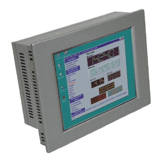
IEI Technology PPC-2706 TFT Panel PC Manuals
Manuals and User Guides for IEI Technology PPC-2706 TFT Panel PC. We have
1
IEI Technology PPC-2706 TFT Panel PC manual available for free PDF download: User Manual
IEI Technology PPC-2706 User Manual (124 pages)
AMD Geode LX800 CPU and Ip65 Protection Panel PC
Brand:
IEI Technology
| Category:
Touch Panel
| Size: 4 MB
Table of Contents
Table of Contents
4
User Manual
1
1 Introduction
11
Ppc-2706/Ppc-2708 Flat Panel Pc Overview
12
Model Variations
12
Applications
12
Standard Features
12
Table 1-1: PPC-2706 and PPC-2708 Model Variations
12
External Overview
13
General Description
13
Front Panel
13
Figure 1-1: PPC-2706/PPC-2708 Front View
13
Figure 1-2: PPC-2706 Rear View
14
Figure 1-3: PPC-2708 Rear View
14
Rear Panel
14
Top Panel
14
Bottom Panel
15
Figure 1-4: PPC-2706 Top View
15
Figure 1-5: PPC-2708 Top View
15
Internal Overview
16
Specifications
16
Preinstalled Hardware Components
16
Figure 1-6: PPC-2706 Bottom View
16
Figure 1-7: PPC-2708 Bottom View
16
System Specifications
17
Motherboard Specifications
18
Table 1-2: PPC-2706/PPC-2708 Specifications
18
Flat Panel Screen
19
PPC-2706 Flat Panel Screen Specifications
19
Table 1-3: Motherboard Specifications
19
Table 1-4: 6.5" TFT LCD Monitor Specifications
20
PPC-2708 Flat Panel Screen Specifications
21
Table 1-5: 8.4" TFT LCD Monitor Specifications
21
Dimensions
22
PPC-2706 Dimensions
22
Figure 1-8: PPC-2706 Dimensions (Units in MM)
22
PPC-2708 Dimensions
23
Figure 1-9: PPC-2708 Dimensions (Units in MM)
23
2 Wafer-Lx Motherboard
24
Introduction
25
Cpu Support
25
AMD Geode™ LX 800 500Mhz Specifications
25
AMD Geode™ LX 800 500Mhz Power Management
26
System Chipset
26
Ethernet Controller Specifications
27
Overview
27
Features
27
Peripheral Device Interfaces, Connectors, and Slots
28
OEM Options
28
Internal Slots
28
Internal Peripheral Device Connectors
28
External Peripheral Device Connectors
29
3 Installation and Configuration
30
Installation Precautions
31
Preinstalled Components
31
Installation and Configuration Steps
31
Unpacking
32
Packing List
33
Remove the
33
PPC-2706 Back Cover Removal
33
Cover
33
PPC-2708 Back Cover Removal
34
Figure 3-1: PPC-2706 Back Cover Retention Screws
34
Figure 3-2: PPC-2708 Back Cover Retention Screws (Real Panel)
34
Jumper Settings
35
JP1: at Power Select Jumper Settings
36
CN7: Clear CMOS Setup
36
Table 3-1: at Power Select Jumper Settings
36
JP2: COM3 Setup Jumper Settings
37
System Fan Installation
37
PPC-2706 System Fan Installation
37
Figure 3-3: Jumper Locations
36
Table 3-2: Clear CMOS Jumper Settings
37
Table 3-3: COM3 Setup Jumper Settings
37
Figure 3-4: PPC-2706 Fan Bracket Removal
38
Figure 3-5: PPC-2706 System Fan Installation
38
Figure 3-6: PPC-2706 Fan Module Cables
39
Figure 3-7: PPC-2706 Fan Connector Location
39
Figure 3-8: PPC-2708 System Fan Installation
40
Figure 3-9: PPC-2708 Fan Module Cables
40
PPC-2708 System Fan Installation
40
Hdd Installation
41
PPC-2706 HDD Installation
41
Figure 3-10: PPC-2706 Fan Connector Location
41
Figure 3-11: PPC-2708 Fan Bracket Installation
41
Figure 3-12: PPC-2706 HDD Bracket Retention Screws
42
PPC-2708 HDD Installation
42
Figure 3-13: HDD Bracket Retention Screws
43
Figure 3-14: PPC-2708 HDD Bracket Retention Screws
43
Compactflash® Card Installation
44
PPC-2706 CF Card Installation
44
Figure 3-15: PPC-2706 Chassis Retention Screws
44
Figure 3-16: PPC-2706 Motherboard Retention Screws
45
Figure 3-17: PPC-2706 Motherboard Copper Pillar
45
Figure 3-18: PPC-2706 CF Card Location
45
Figure 3-19: PPC-2706 Grounding Cable
46
Figure 3-20: PPC-2708 Chassis Retention Screws (Bottom Panel)
46
PPC-2708 CF Card Installation
46
Figure 3-21: PPC-2708 Chassis Retention Screws (Inside)
47
Figure 3-22: PPC-2708 CF Card Location
47
Memory Module Installation
47
Figure 3-23: SO-DIMM Module Installation
48
Installation Steps During Windows XP Installation
49
Installation Steps under Existing Windows XP
50
Sata - al Iraid Driver Installation
48
Mounting the System
51
Wall Mounting
51
Figure 3-24: Wall-Mounting Bracket
52
Figure 3-25: Chassis Support Screws
52
Panel Mounting
53
PPC-2706 Panel Mounting
53
Figure 3-26: Mount the Chassis
53
Figure 3-27: PPC-2706 Panel Opening
54
Figure 3-28: PPC-2706 Panel Mounting
55
Figure 3-29: PPC-2708 Panel Opening
55
PPC-2708 Panel Mounting
55
Arm Mounting
56
Figure 3-30: Tighten the Panel Mounting Clamp Screws
56
Figure 3-31: Arm Mounting Retention Screw Holes
57
Cabinet and Rack Installation
58
PPC-2706 Cabinet and Rack Installation
58
Figure 3-32: the Rack/Cabinet Bracket
58
Figure 3-33: PPC-2706 Rack and Cabinet Mounting
59
Figure 3-34: Install into a Rack/Cabinet
59
Figure 3-35: the Rack/Cabinet Bracket
60
PPC-2708 Cabinet and Rack Installation
60
DIN Mounting
61
Figure 3-36: Secure the Rack/Cabinet Bracket
61
Figure 3-37: DIN Rail Mounting Bracket
62
Figure 3-38: Screw Locations
62
Rear Panel Connectors
63
LCD Panel Connection
63
Figure 3-39: Mounting the DIN RAIL
63
Figure 3-40: Secure the Assembly to the DIN Rail
63
Ethernet Connection
64
Keyboard and Mouse Connection
64
System Maintenance
64
USB Connection
64
4 Gasket Replacement
65
Replacement
65
Figure 4-1: Gasket Replacement
66
5 Ami Bios Setup
67
Introduction
68
Starting Setup
68
Using Setup
68
Getting Help
69
Unable to Reboot after Configuration Changes
69
Main BIOS Menu
69
Table 5-1: BIOS Navigation Keys
69
Exit Without Saving
71
Load Fail-Safe Defaults
71
Load Optimized Defaults
71
Save & Exit Setup
71
Set Supervisor Password
71
Set User Password
71
Date [Day MM:DD:yyyy]
72
IDE Master and IDE Slave
72
Standard Cmos Features
72
Time [Hh/MM/Ss]
72
Drive a [None]
73
Halt on [All, but Keyboard]
73
IDE Primary Master/Slave
74
Base Memory
74
Extended Memory
74
IDE HDD Auto-Detection [Press Enter]
74
IDE Primary Master [Auto]
74
Total Memory
74
Access Mode [Auto]
75
Capacity
75
Cylinder
75
Advanced Bios Features
76
Head
76
Landing Zone
76
Precomp
76
Sector
76
CPU Internal Cache [Enabled]
77
Quick Power on Self Test [Enabled]
77
Virus Warning [Disabled]
77
Boot Device
78
Boot from LAN Control [Disabled]
78
SATA Boot ROM Control [Disabled]
78
Boot Other Device [Enabled]
79
Boot up Floppy Seek [Disabled]
79
Boot up Numlock Status [On]
80
Gate A20 Option [Fast]
80
Typematic Rate (Chars/Sec) [6]
80
Typematic Rate Setting [Disabled]
80
Security Option [Setup]
81
Typematic Delay (Msec) [250]
81
Advanced Chipset Features
82
Delay for HDD (Secs) [3]
82
OS Select for DRAM > 64MB [Non-OS2]
82
Small Logo (EPA) Show [Disabled]
82
Video BIOS Shadow [Enabled]
82
CPU Frequency [500Mhz]
83
Memory Frequency [333Mhz]
83
CAS Latency [Auto]
84
Interleave Select [LOI]
84
Output Display [Panel & CRT]
84
Flat Panel Configuration
85
Video Memory Size [8M]
84
Flat Panel Configuration [Press Enter]
85
Onboard Audio [Enabled]
85
Data Bus Type [9 - 24 Bits, 1 Ppc]
86
Refresh Rate [60Hz]
86
Resolution [800 X 600]
86
HSYNC Polarity [High]
87
Integrated Peripherals
87
LP Active Period [Free Running]
87
SHFCLK Active Period [Free Running]
87
VSYNC Polarity Active [Low]
87
Drive PIO Mode [Auto]
88
On-Chip IDE Channel 1 [Enabled]
88
IDE HDD Block Mode [Enabled]
89
IDE UDMA [Auto]
89
IT8888 ISA Decode IO
89
IT8888 ISA Decode Memory
89
Onboard FDC Controller [Disabled]
90
Onboard Serial Port 1 [3F8/IRQ4]
90
Onboard Serial Port 2 [2F8/IRQ3]
90
Onboard Parallel Port [378/IRQ7]
91
Onboard Serial Port 3 [Disabled]
91
Parallel Port Mode [SPP]
91
ECP Mode Use DMA [1]
92
IT8888 ISA Decode IO
93
EPP Mode Select [EPP1.7]
92
Decode IO Address N 0:15 [XX]
94
Decode IO Size N [Fast Speed]
94
IT8888 ISA Decode Memory
96
Decode IO Space N [Enabled]
94
Decode IO Speed N [Fast Speed]
94
Decode Memory Space N [Enabled]
96
Decode Memory Address N [XX]
97
Decode Memory Size N [XX]
97
Decode Memory Speed N [Fast Speed]
97
Power Management Setup
97
ACPI Function [Disabled]
98
ACPI Suspend Type [S1(POS)]
99
Power Management [ACPI]
99
Standby Mode [Disabled]
99
Suspend Mode [Disabled]
100
PNP os Installed [No]
101
Pnp/Pci Configurations
101
Soft-Off by PWR-BTTN [Instant-Off]
101
Reset Configuration Data [Disabled]
102
Resources Controlled by [Auto (ESCD)]
102
IRQ Resources [Press Enter]
103
Memory Resources [Press Enter]
104
Reserved Memory Base [N/A]
104
Pc Health Status
105
PCI/VGA Palette Snoop [Disabled]
105
Reserved Memory Length [8K]
105
CPU Warning Temperature [Disabled]
106
Shutdown Temperature
106
System Temperature
106
System Fan
107
Voltages
107
A Interface Connectors
108
Peripheral Interface Connectors
109
Tableea-1: at Power Connector (CN1) Pinouts
109
Tableea-2: ATX Power Connector (CN2) Pinouts
109
Tableea-3: ATX Power Button Connector (CN13) Pinouts
109
Tableea-4: Audio Connector (CN8) Pinouts
109
Tableea-5: Battery Connector (CN7) Pinouts
110
Tableea-6: Compact Flash Connector (CN32) Pinouts
110
Tableea-7: Fan Connector (CN4) Pinouts
111
Tableea-8: FDD Connector (CN31) Pinouts
111
Tableea-9: GPIO Connector (CN14) Pinouts
111
Tableea-10: Secondary IDE Connector (CN30) Pinouts
112
Tableea-11: Inverter Power Connector (CN3) Pinouts
112
Tableea-12: Keyboard/Mouse Connector (CN17) Pinouts
113
Tableea-13: LED Connector (CN5) Pinouts
113
Tableea-14: Parallel Port Connector (CN15) Pinouts
113
Tableea-15: Reset Button Connector (CN12) Pinouts
113
Tableea-16: RS-232/422/485 Serial Port Connector (CN16) Pinouts
114
Tableea-17: SATA Drive Connector (CN23 & CN25) Pinouts
114
Tableea-18: TFT LCD LVDS Port Connector (CN29) Pinouts
114
Tableea-19: TFT LCD TTL Port Connector (CN28) Pinouts
115
B Bios Configuration Options
116
B.1 BIOS Configuration Options
117
Bios Configuration Options
117
C Safety Precautions
120
Safety Precautions
121
General Safety Precautions
121
Anti-Static Precautions
122
Product Disposal
123
Maintenance and Cleaning Precautions
123
Maintenance and Cleaning
123
Cleaning Tools
124
Advertisement
Advertisement
Related Products
IEI Technology PPC-2708
IEI Technology PPC2-CW15-ADL
IEI Technology PPC2 ADLP Series PPC2-C104-ADLP-i3/8G
IEI Technology PPC2-C104-ADLP-i5/8G
IEI Technology PPC2-C104-ADLP-i7/8G
IEI Technology PPC2-CW215-ADLP-i7/8G
IEI Technology PPC2-C121-ADLP-I3/8G-R10
IEI Technology PPC2-C104-ADLP-I7/8G-R10
IEI Technology PPC2-C150-ADLP-i3/8G-R10
IEI Technology PPC2-CW133-ADLP-i7/8G
IEI Technology Categories
Motherboard
Touch Panel
Computer Hardware
Single board computers
Desktop
More IEI Technology Manuals
Login
Sign In
OR
Sign in with Facebook
Sign in with Google
Upload manual
Upload from disk
Upload from URL