
Related Manuals for Nortrac NorTrac 35XT


Summary of Contents for Nortrac NorTrac 35XT
- Page 1 NorTrac 35XT Tractor Owner’s Manual Sold By Northern Tool & Equipment, Inc. P.O. Box 1299 Burnsville, MN 55337 Tel.: 1-800-222-5381 www.northerntool.com...
- Page 2 User Notices NorTrac 35XT Tractor Product Identification Data Sheet Product Part Number Product Model Machine Serial Number Chassis Serial Number Engine Model Engine Serial Number Date of Purchase Where Purchased/Contact Information Owner Name Complete this form carefully at purchase. All serial numbers in this form should be recorded completely (including letters).
- Page 3 User Notices Thank You Thank you for purchasing a NorTrac tractor from Northern Tool & Equipment Company. We value you as a customer and wish you many years of safe and satisfied use of your tractor. Using Your Owner’s Manual This Owner’s Manual is an important part of your tractor and should remain with the tractor if you sell it.
- Page 4 Overview This manual describes safety precautions as well as running-in, proper usage, technical maintenance, adjustment, faults and troubleshooting methods for various parts of the NorTrac XT tractors. The manual gives an in-depth look and should be used as a reference tool for owners and maintenance personnel. In this manual, the safety alert symbol prompts important safety information.
-
Page 5: Table Of Contents
Table of Contents Table of Contents 1. Safety Precautions ........................... 1 1.1 Safety rules and notices of use......................... 1 1.2 Safety warning symbols........................... 6 1.3 Preventing farm machine hazards......................10 2. Operating Instructions .......................... 14 2.1 Product description ..........................15 2.2 Tractor operating controls and instrumentation .................. - Page 6 Table of Contents 4.9 Air filter use and maintenance ....................... 63 4.10 Fan belt tensioning adjustment ......................64 4.11 Engine oil maintenance and changing the oil ..................65 4.12 Fuel filter maintenance ........................66 4.13 Engine oil filter maintenance....................... 66 4.14 Lifter hydraulic oil filter maintenance ....................
-
Page 7: Safety Precautions
Safety Precautions 1. Safety Precautions 1.1 Safety Rules and Notices of Use Reading Prior to Use The instructions for use, maintenance, and the safety warning identifiers should be fully read and understood. The correct usage and operating method should be observed. Local traffic rules and safety regulations must be observed at all times. - Page 8 Safety Precautions Waste Oil Disposal 1. Used machine oil is a hazardous waste. Dispose of it properly. 2. The used acid from the battery is also a hazardous waste. Dispose of it properly. Waste oil disposal Fig.1-5 Hydraulic Line Leaks Do not use your hand to check for leaks in the high-pressure hydraulic oil lines.
- Page 9 Safety Precautions Emergency Procedures 1. In case of a brake failure, hold the steering wheel firmly, wait until the tractor has come to a complete stop and then shut down the engine. 2. If the steering malfunctions, brake immediately and shut down the engine. 3.
- Page 10 Safety Precautions tipping. 10. When crossing or going under a bridge or going through a tunnel, pay full attention to the load height. 11. Use the lowest gear with the clutch enabled on a down slope. Never put the tractor in neutral and coast downhill as this can cause instability.
- Page 11 Safety Precautions under load, as this can damage the universal joint or the PTO shaft. When the PTO shaft is not in use, the PTO lever should be returned to the neutral position. After parking and before shutting down the tractor, the driver should remove the key from the ignition, set all gearshift levers to the neutral position, and lock the brake handle.
-
Page 12: Safety Warning Symbols
Safety Precautions the tractor. 5. Antifreeze should always be used in the engine cooling system. 6. The front driving axle of tractor should only be engaged in agricultural instances and when roads are muddy. Overuse of the front drive axle may result in premature wear of the tires and transmission problems. - Page 13 Safety Precautions Please keep a safe distance from the tractor when it is operating, to avoid any personal injuries. Location: left from the rear side of mudguard. Fig. 1-11 Safety warning identifier Never sit on the fender when the tractor is operating as this could result in falling from the vehicle and possible injury.
- Page 14 Safety Precautions Always start the engine from a secure position in the driver’s seat. Location: in front of the instrument panel. Fig. 1-16 Safety startup symbol Read and understand all instruction for use, including the meaning of all non-lettered safety symbols. Location: in front of the instrument panel.
- Page 15 Safety Precautions For battery service, carefully read the instructions in order to understand the correct maintenance procedures. Location: on the surface of the battery. Fig. 1-20 Battery symbol To prevent from fire To prevent the risk of fire, never refuel the tractor while it is running. 1 It is prohibited to refuel on the work site and during the operation of tractor...
-
Page 16: Preventing Farm Machine Hazards
Safety Precautions 1.3 Preventing Farm Machine Hazards The following article describes important general safety precautions for machinery such as the NT-204C/NT-254 tractor. It is reprinted here with permission from Professor Thomas L. Bean, Safety Leader and Professor, Department of Food, Agricultural, and Biological Engineering, The Ohio State University Extension, The Ohio State University. - Page 17 Safety Precautions Both shear and cutting points are created on machinery designed to cut, such as harvesters, and on those that are not designed to cut, such as augers. They are hazardous because of their cutting force and they often move so rapidly that they may not be visible, so it is easy to forget they are operating or to underestimate the hazard.
- Page 18 Safety Precautions Check all equipment for potential wrap points and, if possible, shield those that can be shielded. Replace any damaged manufacturer-installed warning labels and place warnings on equipment parts not previously labeled. In addition, consider painting them a bright color, perhaps with wide stripes. Be aware of wrap points and be alert to their danger.
- Page 19 Safety Precautions Springs Compressed springs (Fig. 4 below) will expand with great force when released, and springs that are stretched will contract rapidly when released. Know what direction a spring will move and how it might affect another machine part when released, and stay out of its path. Figure 4 Burn Points Be aware of burn points: mufflers, manifolds and even gear cases under adverse climatic conditions.
-
Page 20: Operating Instructions
Operation Description 2. Operator Instruction NOTE: operating the tractor properly can maximize the efficiency of the tractor, reduce tractor wear, and prevent accidents. It can enable the operator to complete farm and road operations fast, efficiently and safely with low fuel consumption. Table 2-1 Common symbols Symbols Definition... -
Page 21: Product Description
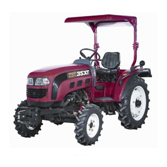
The following information will help you use, maintain, and troubleshoot the NorTrac 35XT series tractor. The NorTrac 35XT tractor is a medium-sized tractor that can be used on a variety of types of land. The tractor has a compact structure and is easy to control with responsive steering, a high lift capacity and low maintenance. - Page 22 Operation Description 2.2.2 Instruments and Switches 1. Fuel Gauge 2. Water Temperature Gauge 3. Tachometer 4. Hour Meter 5. Oil Pressure Gauge 6. Ampeter Figure 2-2 Instrument Panel IMPORTANT ISSUES : Observe all warning lights and pay attention to the instrument panel during operations.
- Page 23 Operation Description Water Temperature Gauge The Water Temperature Gauge displays the engine cooling fluid temperature, increasing from left to right with the red area indicating high temperature Figure 2-4 Water Temperature Gauge Engine Tachometer and Hour Meter The Engine Tachometer shows the operating rotary speed of the engine in rpm once the tractor is started.
- Page 24 Operation Description Engine Oil Pressure Warning Light When the key is turned to the ignition position this light is lit. After the engine starts the light will go out. This means the oil lube system pressure is normal. When the engine is idling, the light may come on because it is normal that pressure in the lubrication system is low during idling.
- Page 25 Operation Description Right Rocker Switch Combination 1 Headlight Switch 2 Hazard Warning Switch Figure 2-12 Right Rocker Switch Combinations Headlight Switch Position “1”: The headlights are dimmed (low beams). Position “0”: The headlights are off. Position “2”: The high beams are on. There are also headlight indicator lights on the instrument panel to indicate high/low beams.
-
Page 26: Ignition Switch
Operation Description Horn The horn is in the center of the steering wheel. Press down the horn button shown in the figure, and the horn will sound. Figure 2-15 Horn Ignition Switch Insert the key into the electric switch and turn it clockwise to the following positions: •... -
Page 27: Starting The Engine
Operation Description 2.3 Starting the Engine WARNING : Before operating, the tractor should be checked over thoroughly to eliminate potential accidents or breakdowns. 2.3.1 Engine Starting Preparations • Before starting the tractor, inspect for damaged or loose parts and leakage. •... - Page 28 Operation Description 2.3.3 Engine Starter IMPORTANT ISSUES: 1. Release the key immediately after starting of engine. The key will return to the ON position automatically (see Figure Igniting Lock). If not released, the engine will continue to rotate the starter, causing damage. 2.
-
Page 29: Driving The Tractor
Operation Description 2.3.4 Running the Engine • After the engine is started, ease up on the throttle immediately to allow the engine to run at idle. Check the engine oil pressure to ensure that the indicator on the oil pressure gauge is in the green zone. •... -
Page 30: Steering The Tractor
Operation Description 2.5 Steering the Tractor 1. When driving the tractor on the road, switch on the turn indicator (left or right) and reduce speed before making the turn. If you have to make a large turn, make the turn at a slow speed. 2. -
Page 31: Differential Lock Operation
Operation Description WARNING: 1. Bring the tractor to a full and complete stop before shifting between forward and reverse gears. Not doing so can damage the transmission. Always depress the clutch when shifting between forward and reverse, between low and high gear ranges, or when shifting gears. -
Page 32: Tractor Braking
Operation Description Disconnecting the Front Drive Axle Step on the clutch pedal. Push the control handle of the front drive axle forward to disconnect the front drive axle. IMPORTANT ISSUES : When driving the tractor on a hard-surface road, never connect the front drive axle. Engaging the front drive axle will cause front wheel wear and tear and increase fuel consumption. -
Page 33: Stopping The Tractor And Engine Shutoff Procedure
Operation Description 2.10 Stopping the Tractor and Engine Shutoff Procedures 1. Throttle down to decrease the engine speed. 2. Step on the clutch pedal, then the brake pedal and engage the parking brake. When the tractor stops moving, put the gearshift in neutral. The auxiliary shift lever (high/low gear range selector) and the shuttle shift lever (forward and reverse) can be left where they are. -
Page 34: Counterweight
Operation Description • The front wheel alignment and toe-in should be checked regularly. Failure to do so can result in excessive tire wear. When tire wear is nonuniform, the left and right tires can be switched. IMPORTANT ISSUES : The inflation pressure for the front and rear tires on a 4-wheel drive tractor should be the same in order to prevent the tires from being worn unevenly. -
Page 35: Driver's Seat Adjustment
Operation Description 2.13 Driver’s Seat Adjustment The driver seat for series XT tractors can be adjusted in forward and backward direction. To adjust the seat, turn the adjustment handle (A) on the outside lower left of the driver’s seat (see diagram). At the same time, move the seat forward or backward. - Page 36 Operation Description 2.14.2 Lowering Speed Adjustment Select a suitable lowering speed for the farm implement to keep it from being damaged by heavy impact when it contacts the ground. Before delivery of the tractor, the descending speed regulating valve was adjusted. The owner/operator can readjust the valve according to the weight of farm implement and ground hardness.
- Page 37 Operation Description WARNING : When transporting implements in the raised position over long distances, the hydraulic lock should be used to lock the implements in place. This will prevent an accidental move of the distributor control handle from making the farm implements drop suddenly and cause damage 2.14.5 Hydraulic Control Levers There are three levers that control the hydraulic system for farm implements towed by the tractor.
- Page 38 Operation Description IMPORTANT ISSUES: 1. When a quick disconnect is not used, the connector seat should be covered with a seal cover to avoid dust. After the hydraulic output device is used, the operating handle should be set to the neutral position, otherwise, the hydraulic system may overheat.
- Page 39 Operation Description IMPORTANT ISSUES 1. When plowing, never adjust the traction of the farm machinery by adjusting the limit rod. Instead, reduce the number of plowshares (blades) to match the tractor’s pulling capacity. This will help you avoid damaging the suspension mechanism.
- Page 40 Operation Description 2.14.8 Power Take Off (PTO) Shaft Use To connect and disconnect power to the power take off (PTO) shaft the double-acting clutch, the PTO gear shift handle, and the PTO disconnect control handle are used. When the clutch pedal is pushed down part way it disconnects the engine clutch, and when it is pushed down all the way down it disconnects the PTO clutch.
- Page 41 Operation Description 2.14.9.1 Battery The battery is used to store the electrical energy produced by the alternator. The battery can then supply electrical power to the electrical equipment on the tractor when the alternator is not turning or is running at low speed. It can also help with the power supply when the alternator is overloaded for a brief period.
- Page 42 Operation Description...
-
Page 43: Tractor Break-In
Operation Description 2.15 Tractor Break-in Before the tractor is put into service, it should run for a certain period under the specified conditions of lubrication, rotational speed and load, and at the same time have any necessary inspection, adjustments and maintenance, to normalize its technical state;... - Page 44 Operation Description The following types of break-in should not be implemented unless the engine is functioning normally. 2.15.3 Power Take Off Shaft Idle Break-in Put the throttle control handle in the medium position and let the engine run at medium speed. Let the power take off shaft run 5 minutes in low speed and 5 minutes in high speed and check for abnormalities.
- Page 45 Operation Description 2.15.5 Tractor Idle and Loaded Break-In After the engine idle, power take off shaft and hydraulic system break-in tests, confirm that the mechanical state of the tractor is normal before implementing the break-in of the whole tractor according to Tables 2-2 and 2-3. The total break-in time is 50 hours.
- Page 46 Operation Description front drive axle according to the specifications. • Carry out the technical maintenance for the diesel engine according to the specifications of the Diesel Engine Use and Maintenance Operation Manual. • Drain the engine coolant then add new coolant, with a 50/50 water/antifreeze mixture. Never run the engine without coolant in the cooling system.
- Page 47 Maintenance Instructions Table 2-1 Break-in Time for Each Stage Unit: hours Tractor Gear Forward Gear Reverse Gear High High High High High High High High Idle, no load Loaded with 3t weight with a trailer, road transportation should used Operating on sandy soil with a plow,...
-
Page 48: Tractor Faults And Troubleshooting
Maintenance Instructions Fault Causes Troubleshooting (1) The heads of the three clutch Make adjustments according fingers are not in the same plane. requirements. (2) The clutch plate and the clutch (2) Clean the friction plate and the clutch 3. The tractor shakes when fingers have grease on them. - Page 49 Maintenance Instructions 2.16.1.3 Rear Axle and Brake Faults and Troubleshooting Table 2-4 Rear Axle and Brake Faults and Troubleshooting Fault Causes Troubleshooting (1) The bearing play of the small conical (1) Adjust according to requirements. gear is too large. (2) Readjust according to (2) Gear engagement is abnormal.
- Page 50 Maintenance Instructions 2.16.1.4 Four-Wheel Drive System Faults and Troubleshooting Table 2-5 Four-Wheel Drive System Faults and Troubleshooting Fault Causes Troubleshooting (1) The rim or the radial plate of the front (1) Align the front wheel rim or wheel is deformed. the radial plate.
- Page 51 Maintenance Instructions 2.16.1.5 Hydraulic Steering System Faults and Troubleshooting Table 2-6 Hydraulic Steering System Faults and Troubleshooting Fault Causes Troubleshooting (1) Rubber O-rings at various pipe joints are (1) Replace the O-ring or damaged or loose. tighten the fitting. (2) O-rings in hydraulic steering gear valve (2) Clean or replace the O- ring.
- Page 52 Maintenance Instructions (1) The clearance between the valve core and (1) Replace valve. the valve housing is too large. (2) Replace shaft or pin. (2) The clearance between the interlocking shaft (3) Replace shaft or rotor. 5. Steering is slow to and the fork pin is too large.
- Page 53 Maintenance Instructions Fault Causes Troubleshooting (3) Gear oil pump failure. (4) Add lubricating oil according to the (4) Hydraulic oil level is too low. requirements. (1) The tightness of the check valve in (1) Clean the check valve. the hydraulic flow hydraulic flow (2) Clean or replace the lowering valve.
- Page 54 Maintenance Instructions 2.16.2 Electrical System Faults and Troubleshooting 2.16.2.1 Starter Faults and Troubleshooting Table 2-9 Starter Faults and Troubleshooting Fault Causes Solutions (1) Battery capacity is insufficient. Charge battery (2) Battery terminal is dirty of the cable is loose according to the specifications. (3) Cable connection is loose (2) Remove dirt and corrosion (4) The wires in control circuits such as the start...
- Page 55 Maintenance Instructions 2.16.2.2 Alternator Faults and Troubleshooting Table 2-10 Alternator Faults and Troubleshooting Fault Causes Solutions (1) Wiring is wrong, broken, and/or (1) Check and repair the circuits. making poor contact. (2) Replace alternator. (2) Rotor circuit broken. (3) Replace alternator. 1.
- Page 56 Maintenance Instructions 2.16.2.4 Instrument Faults and Troubleshooting Table 2-12 Instruments Faults and Troubleshooting Fault Causes Solutions (1) Break in the circuit or the plug is making poor (1) Overhaul the circuit, or 1. The water temperature contact. remove the dirt at the plug. gauge always indicates a (2) The water temperature sensor is damaged.
-
Page 57: Accessories And Consumables
Accessories and Consumables Accessories and Consumables 3.1 Accessories 3.1.1 Safety Frame (optional) The 35XT series tractor can be equipped with an OSHA safety frame to prevent the driver from being hurt by an accidental turnover. 3.2 List of Consumables (Not Included With Tractor Purchase) Table 3-1 List of Consumables, Such As Bulbs, Glass Products, Filters, etc. -
Page 58: Maintenance Instructions
Maintenance Instructions 4. Maintenance Instructions 4.1 Technical Maintenance Procedures Carrying out the technical maintenance specifications of the tractor is the effective way to prolong the service life of the tractor and reduce accidents. The technical maintenance schedule for 35XT series tractors is based on the accumulated work hours, which includes maintenance for: every shift (per 10 work hours), every 50 work hours, every 200 work hours, every 400 work hours,every 800 work hours, every 1600 work hours, and winter and long-term storage. - Page 59 Maintenance Instructions 4.1.2 Technical Maintenance for Every 50 Hours 1. Perform all the requirements of the technical maintenance per shift. 2. Check the air filter and remove the dust. 3. Check the tightness of the fan belt. When pressing the belt, it should deflect 15 - 20mm (0.6 - 0.8 in.).
- Page 60 Maintenance Instructions 4.1.6 Technical Maintenance for Every 1600 Hours 1. Perform all technical maintenance required for every 800 work hours. 2. Check engine to manufacturer’s specifications. 3. Change the lube oil in the central drive and the final drive of the front drive axle. 4.
- Page 61 Maintenance Instructions Table 4-1 35XT Series Tractors Maintenance Table Maintenance Part Operation Content No. of Maintenance Points Interval Engine Oil Pan Check Oil Level Per Shift Battery Check Connections Per Shift Radiator Check Coolant Level Per Shift Fuel Injection Pump Check Oil Level Per Shift Clutch...
-
Page 62: Clutch Adjustment
Maintenance Instructions Clutch Adjustment In order to ensure the normal operation of the clutch, a clearance of (2–2.5mm) should be kept between the end of disengaging lever 4 of the main clutch and the surface of release bearing 5; a clearance of B = (10–11mm) should be kept between the end of disengaging lever 6 of the auxiliary clutch and the surface of release bearing 5. - Page 63 Maintenance Instructions IMPORTANT ISSUES: 1. Adjusting the clutch requires technical skills and specific tools. If uncomfortable completing this task call NorTrac Technical Support. 2. In order to keep the friction plate from the oil, keep drain hole clear of any blockage below the flywheel casing.
-
Page 64: Brake Adjustment
Maintenance Instructions 4.3 Brake Adjustment 4.3.1 When Any of the Following Occurs, the Brake Should Be Adjusted: • The free play of the brake pedal is too large, which can cause a braking failure. • The free play of the brake pedal is too small, which can cause too little clearance between the brake shoe and the brake drum and cause the brakes to drag. -
Page 65: Differential Lock Adjustment
Maintenance Instructions WARNING Adjust the free strokes so that the left and right brake pedals are consistant, or the tractor will turn to one side during hard braking, which can cause an accident. 4.4 Differential Lock Adjustment Adjustment of differential lock is performed through adjustment of the bolts (1 and 2). During the adjustment, the clearance between the right coupling (3) and left coupling (4) is about 2mm. -
Page 66: Steering System Adjustment
Maintenance Instructions 4.5 Steering System Adjustment 4.5.1 Full Hydraulic Steering System Precautions The 35XT Series 4-wheeled tractors use a full hydraulic steering mode, as shown in the following figure. Before each tractor leaves the factory the steering system is adjusted. Pay attention to the following when using the tractor: •... -
Page 67: Front Drive Axle Adjustment
Maintenance Instructions 4.6 Front Drive Axle Adjustment 4.6.1 Front Drive Axle Side Drive Adjustment Adjustment of the side clearance between the drive gear and driven gear of the first level intermediate drive of the side drive of the front drive axle can be done by adjusting the adjusting shim (1). Adjustment of the side clearance between the drive gear and the driven gear of the second level and drive can be accomplished by adjusting the adjusting shim (5). -
Page 68: Hydraulic Lifting Mechanism Adjustment
Maintenance Instructions 4.7 Hydraulic Lifting Mechanism Adjustment First put the farm implement raise and lower control handle in the neutral position as shown in the following figure. Then adjust the distance between the block on the push rod and the stop pin fixed on the lift shaft. -
Page 69: Battery Maintenance
Maintenance Instructions 4.8 Battery Maintenance 4.8.1 Maintenance of Maintenance-free Battery • Inspection of the Battery. Normally the maintenance-free battery does not require any special maintenance. You can observe the power levels from the view hole of the liquid densimeter: Green=full power; Grey=lack of power; Dark=no power. -
Page 70: Fan Belt Tensioning Adjustment
Maintenance Instructions 4.9.2 Air Filter Maintenance • Take out the air filter element. Use a brush to clean the inner case of the air filter and remove the dust from the rubber dust bag. • Turn the filter element, and use compressed air of less than 500KPa (72.5 psi) to blow the dust from the inside of the filter element. -
Page 71: Engine Oil Maintenance And Changing The Oil
Maintenance Instructions 4.11 Engine Oil Maintenance and Changing the Oil (1)Raise the tractor hood and remove the oil dipstick (A) in top right of the engine, and check whether the oil level is between the upper scale mark and the lower scale mark. -
Page 72: Fuel Filter Maintenance
Maintenance Instructions 4.12 Fuel Filter Maintenance The diesel fuel filter is located on the top left of the engine. Open the tractor hood to access it. Never wash the paper filter element of the filter. The fuel filter element should be replaced after every 200 working hours. -
Page 73: Front Drive Oil Level Maintenance
Maintenance Instructions 4.15 Front Drive Oil Level Maintenance When checking the front drive oil level, the oil dipstick (A) should be unscrewed and the oil level should fall within the scale range on the dipstick, Otherwise, oil needs to be added. The left and right final drives also have fill ports where the oil level can be checked. -
Page 74: Lifter Assembly Maintenance
Maintenance Instructions 4.17 Lifter Maintenance • Unscrew the oil dipstick (A) on the hydraulic auxiliary tank located above the lifter (as shown in Figure 4-19). If the oil level does not reach the lower scale mark, oil should be added. •... -
Page 75: Engine Cooling System Maintenance
Maintenance Instructions 4.20 Engine Cooling System Maintenance The engine cooling system uses a 50/50 water/antifreeze blend. In general the antifreeze is good for a period of 2 years or 1,600 hours. After that the coolant should be replaced. The cooling system should be flushed out before new coolant is added. -
Page 76: Storage
Storage 5 Storage When the tractor is going to be out of use for an extended period of time (more than one month) it should be kept in a proper storage building. The storage facility should provide protection from the elements so as to keep the tractor clean and prevent rust and corrosion. -
Page 77: Tractor Storage Maintenance
Storage 5.3 Tractor Storage Maintenance • Check on the tractor and its parts at least once a month to see whether there is any rust, corrosion, aging and distortion happenings • Start the tractor bi-monthly and allow the engine to run. This will prevent interior rust. •... -
Page 78: Transportation
Transportation 6 Transportation If the tractor is transported by driving it, local traffic regulations should be strictly observed with at least 180 feet of distance maintained between vehicles. If the tractor is being transported by truck or train, the following points should be followed: 1. -
Page 79: Technical Specifications
Technical Specifications for 35XT Series Tractors 7. Technical Specifications 7.1 Main Technical Specifications for 30XT Series Tractors Table 7-1 Main Technical Specifications for NorTrac 35XT Series Tractors 35XT Model Unit Type —— 4×4 Wheeled Rated Traction Force Maximum Power of the Power 21.88... - Page 80 Technical Specifications for 35XT Series Tractors Model Unit 35XT Cylinder Diameter × 85×95 Stroke Nominal Power 25.7 Nominal Speed r/min 2,350 Maximum N·m/ Torque/ ≥124/1,650±100 Rotational Speed Specific Fuel Consumption ≤248 Rated Conditions (g/k W h) Engine Consumption ≤2.04 Rated Conditions Lubrication ——...
- Page 81 Technical Specifications for 35XT Series Tractors Model Unit 35XT Axle Differential —— Closed Type, 2 Bevel Planet Gears Mechanism Differential Lock —— Teeth Embedding Type Rear Final Drive —— Built-in Type, Single Straight Spur Gear Rack —— Half Rack Type Tire Front Wheel 200~250...
- Page 82 Technical Specifications for 35XT Series Tractors Model Unit 35XT Specific M22×1.5 or NPT1/2 —— ation Form —— Non-Independent Type Power Take φ35, 6 Tooth Rectangle Spline Shaft (φ35, 8 tooth rectangle Specification —— spline shaft may be selected) Shaft Rotational Speed r/min 540/1,000 Tractio...
- Page 83 Technical Specifications for 35XT Series Tractors Model Unit 35XT Radiator Fuel Tank Engine Oil Pan Filling Used Capacity Transmission Box Oil Used in Lifter Oil Used in Front Drive Axle...
-
Page 84: Disassembly And Disposal
Disassembly and Disposal 8. Disassembly and Disposal After the machine reaches the end of its service life, for your personal safety and the protection of the environment, please deliver it to the licensed company specialized in the disassembly and recycle of such products. -
Page 85: Limited Warranty
Limited Warranty LIMITED WARRANTY 4WD Diesel Tractor & Compact Crawler / Bulldozer NorTrac™ equipment is sold by NorTrac; a division of Northern Tool & Equipment Company, Inc. NorTrac will repair or replace, at its option, any part(s) thereof of the NorTrac™ 4WD diesel tractor or compact crawler / bulldozer that are shown to be defective in material and/or workmanship, under normal use during the applicable warranty period. - Page 86 Limited Warranty This limited warranty does not extend to use in applications for which the equipment was not designed or to damages resulting from misuse, abuse, or neglect. Disclaimer of Consequential Damage: Any implied warranty of merchantability or fitness for a particular purpose, to the extent that either may apply to any NorTrac™...
-
Page 87: Appendices
Appendices Appendices 10.1 Tractor Fuel, Oils and Solutions Table 10-1 Tractor Fuel, Oils and Solutions Application Locations Fuel, Oils and Solutions Oils Solutions Adopt ASTM D-975 fuel. Under general air temperatures, use 2-D International Fuel Tank grade fuel; when ambient temperatures are below 32 F, use 1-D grade standard fuel. -
Page 88: Main Bolts, Screws And Nuts Tightening Torque
Appendices 10.2 Main Bolts, Screws and Nuts Tightening Torque Table 10-2 Main Bolts, Screws, and Nuts Tightening Torque Table Thread Tightening Tightening Name and Assembly Position Specification Torque [N·m] Torque [LB FT] The bolt and nut connecting the engine and the 41~51 30~37 clutch housing. -
Page 89: Tractor Bearings
Appendices WARNING: When tightening the major bolts and nuts on the tractor, torque wrenches should be used to avoid a reduction in machine performance and personal injury, which is caused by a failure to meet the requirements for the tightening torques. 10.3 Tractor Bearings Table 10-3 Detailed List of Tractor Bearings... - Page 90 Appendices Bearing Code Bearing Name Assembly Position Quantity Code Front of the Power Take Off Shaft Rear of the Output Shaft of the Transfer Case Outer End of the Short GB/T 276 6307 Ball Bearing Half Axle Front of the Primary Shaft GB/T 276 6207N Ball Bearing...
- Page 91 Appendices Bearing Code Bearing Name Assembly Position Quantity Code Lower End of the Front Final Drive Shell Release Bearing of the 688711 Release Bearing Clutch Intermediate Shaft of the GB/T 5,846 K202,417 Needle Bearing Transfer Case Output Shaft of the GB/T 5,846 K25,3120 Needle Bearing...
-
Page 92: Seals On The Tractor Chassis
Appendices 10.4 Seals on the Tractor Chassis: Table 10-4 Detailed List of Tractor Chassis Seals Component Specification Assembly Position Qty. B35×55×8 Front of the Primary Shaft GB/T 9877.1 Inside of the Bearing Cover FB35×55×8 Rotary Shaft Lip of the Power Take Off Shaft Seal B50×72×8 Outside of the Drive Shaft... - Page 93 Appendices Component Specification Assembly Position Qty. Upper End of the Left and GB/T3,452.1 Right Steering Knuckle 30×3.55G O-Ring Both Ends of the Rocker Shaft GB/T9,877.1 Steering Rotary Shaft Lip B30×45×8 Steering Pitman Arm Shaft Gear Seal JB/T2,600 PD42×62×10 Lift Shaft Oil Seal 10×13.5 Oil Drain Plug...
- Page 94 Appendices Component Specification Assembly Position Qty. Shell Junction Surface of the Lifter 19×2.65G Shell Oil Pump 18×2.65G Suction Area of the Oil and Oil GB/T3,452.1 O-Ring 18×2.65G Pump Passage JB/T2,600 Output Shaft of the Transfer SG30×45×8 Oil Seal Case Shifting Fork Shaft of the 12.5×1.8G Transfer Transfer Case...
- Page 95 Appendices Component Specification Assembly Position Qty. 80×3.55G Back Support Bearing Block of the Mater 85×3.55G Pinion Shaft 170×3.55G Drive Shaft Cover Inner End of the Half Axle 175×3.55G Sleeve ATTENTION: Before using farm implements, operators should carefully read the “Use and Maintenance Instructions”...
- Page 96 On Line Spare Parts System Fill in Choose English http://222.132.52.85:8080/ Choose “Guest” Choose “Parts catalogue” Choose product Model and Code:...
- Page 97 Then search here TE25 Serials TE354-L161Q1K Then you can find the parts catalog and diagram of the tractor: TE25 Serials TE354-L161Q1K...
- Page 98 TE25 Serials TE354-L161Q1K...
Need help?
Do you have a question about the NorTrac 35XT and is the answer not in the manual?
Questions and answers