
Related Manuals for Nortrac XT20


Summary of Contents for Nortrac XT20
- Page 1 Nortrac XT20 and XT25 Tractors Owner’s Manual Sold By Northern Tool & Equipment, Inc. P.O. Box 1299 Burnsville, MN 55337 Tel.: 1-800-222-5381 www.northerntool.com YFXT20-25MAN...
- Page 2 Nortrac 20XT and 25XT Tractors Product Identification Data Sheet Product Part Number Product Model Machine Serial Number Chassis Serial Number Engine Model Engine Serial Number Date of Purchase Where Purchased/Contact Information Owner Name Complete this form carefully at purchase. All SNs in this form should be recorded completely (including letters).
- Page 3 User Notices Thank You Thank you for purchasing a NorTrac tractor from Northern Tool + Equipment Company. We value you as a customer and wish you many years of safe and satisfied use of your tractor. Using Your Owner’s Manual This Owner’s Manual is an important part of your tractor and should remain with the tractor if you sell it.
- Page 4 This manual describes safety precautions as well as running-in, proper usage, technical maintenance, adjustment, faults and troubleshooting methods for various parts of the Nortrac XT tractors. The manual gives an in-depth look and should be used as a reference tool for owners and maintenance personnel.
-
Page 5: Table Of Contents
Table of Contents Table of Contents 1.Safety Precautions .............................1 1.1 Safety rules and notices of use .........................1 1.2 Safety warning symbols ...........................6 1.3 Preventing farm machine hazards......................10 2. Operating Instructions...........................14 2.1 Product description..........................15 2.2 Tractor operating mechanism and instructions ..................15 2.3 Starting the engine..........................20 2.4 Starting the tractor ..........................22 2.5 Steering the tractor ..........................22... - Page 6 Table of Contents 4.8 Battery Maintenance..........................55 4.9 Dry air cleaner instructions ........................56 4.10 Fan belt adjustment..........................56 4.11 Engine oil sump level check and oil replacement.................57 4.12 Fuel filter maintenance .........................57 4.13 Engine oil filter maintenance........................58 4.14 Lifter hydraulic oil filter maintenance....................58 4.15 Front drive oil level check ........................58 4.16 Transmission mechanism maintenance ....................59 4.17 Lifter assembly maintenance ........................59...
-
Page 7: Safety Precautions
Safety Precautions 1. Safety Precautions 1.1 Safety Rules and Notices of Use Reading Prior to Use The instructions for use, maintenance, and the safety warning identifiers should be fully read and understood. The correct usage and operating method should be observed. Local traffic rules and safety regulations must be observed at all times. - Page 8 Safety Precautions Waste Oil Placement 1. Used machine oil is a waste fuel substance. Do not discard at random. 2. The used acid from the battery is harmful to the environment. Do not discard at random. Waste oil placement Fig.1-5 Pipeline Leaks Do not use your hand to check for leaks in the high-pressure oil pipe.
- Page 9 Safety Precautions Emergency Procedures In case of a brake failure, hold the steering wheel firmly, wait until the tractor has come to a complete stop and then shut down the engine. If the steering malfunctions, brake immediately and shut down the engine. If fire should occur, immediately shut down the engine.
- Page 10 Safety Precautions your vehicle when riding on the road shoulder. 16. Never overload the tractor. Running the tractor over the specified limits can cause damage to the tractor and can result in injury. 17. When driving at night, make sure that you have proper lighting to avoid any collisions. 18.
- Page 11 Safety Precautions Important: 1. Always operate the tractor according to the specified running-in requirements. This will prolong the life of your tractor. 2. Prior to starting the tractor, the oil system, cooling system and electric circuits must be examined. After startup, strict attention should be paid to the various instruments. 3.
-
Page 12: Safety Warning Symbols
Safety Precautions When detaching the tractor from any implements, the upper lever of the suspension unit should be adjusted to the shortest travel and the limit lever adjusted to prevent the implements from swinging out of control. The locking nuts on the upper and limit levers must be tighten in order to guarantee travel safety and to avoid damage to the tractor and the machinery. - Page 13 Safety Precautions Never sit on the fender when the tractor is operating as this could result in falling from the vehicle and possible injury. Post position: front side of the mudguard. Fig. 1-12 Safety warning identifier VI To avoid injury, stay a safe distance from the lifting lever when the lifting lever control system is in operation.
- Page 14 Safety Precautions Always start the engine from a secure position in the pilot seat. Post position: in front of the instrument panel. Post position: in front of the instrument panel. Fig. 1-16 Safety startup symbol Read and understand all instruction for use, including the meaning of all non-lettered safety symbols.
- Page 15 Safety Precautions For battery service, carefully read the instruction for use to understand the correct maintenance procedures. Post position: on the surface of the battery. Fig. 1-20 Battery symbol To prevent the risk of fire, never refuel the tractor while it is running. To prevent from fire 1 It is prohibited to refuel on the Clean grease, fuel and oil spill immediately.
-
Page 16: Preventing Farm Machine Hazards
Safety Precautions Preventing Farm Machine Hazards The following article describes important general safety precautions for machinery such as the NT-204C/NT-254 tractor. It is reprinted here with permission from Professor Thomas L. Bean, Safety Leader and Professor, Department of Food, Agricultural, and Biological Engineering, The Ohio State University Extension, The Ohio State University. AEX-593-91 Thomas L. - Page 17 Safety Precautions Both shear and cutting points are created on machinery designed to cut, such as harvesters, and on those that are not designed to cut, such as augers. They are hazardous because of their cutting force and they often move so rapidly that they may not be visible, so it is easy to forget they are operating or to underestimate the hazard.
- Page 18 Safety Precautions increase with shafts that are not round. Clothing is more likely to catch if there is dried mud or manure on the shaft, or if the shaft is nicked. Ends of shafts that protrude beyond bearings are also dangerous. Universal joints, keys and fastening devices can also snag clothing.
- Page 19 Safety Precautions Springs Compressed springs (Fig. 4 below) will expand with great force when released, and springs that are stretched will contract rapidly when released. Know what direction a spring will move and how it might affect another machine part when released, and stay out of its path. Figure 4 Burn Points Be aware of burn points: mufflers, manifolds and even gear cases under adverse climatic conditions.
-
Page 20: Operating Instructions
Operation Description 2. Operator Instruction Note: operating the tractor properly can bring efficiency of the tractor into full play to reduce tractor wear and prevent an accident and ensure operator to complete farm and road operations fast, efficiently, in low consumption and safety mode Table 2-1 Common symbols Symbols... -
Page 21: Product Description
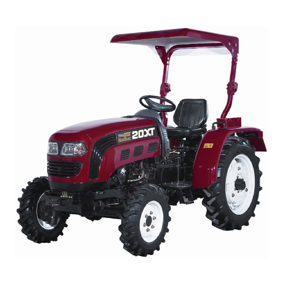
XT20 and XT25 The Nortrac XT series of tractors is a medium-sized tractor that can be used in a variety of land types. The tractor has a compact structure and is easy to control with responsive steering, a high lift capacity and low maintenance. - Page 22 Operation Description Instrumentation and Switches Figure 2-2 Instrumentation and Switches 1. Left rocker switch assembly 2. Start relay 3. Pressure regulator 4. Fuse box assembly 5. Ignition switch 6. Combined instrument 7. Right rocker switch assembly 8. Fuse box assembly IMPORTANT NOTES: Observe all warning lights and pay attention to the instrument panel during operations.
- Page 23 Operation Description Engine tachometer The engine tachometer shows the operating rotary speed of the engine once the tractor is started. Tractor running hours are displayed in the lower box. Figure 2-5 Engine Tachometer Amp meter The Amp meter is used to indicate the status of the battery. The indicator will be in the + when the battery is properly charged.
- Page 24 Operation Description Left Rocker Switch Assembly 1. Signal switch 2. Light switch Figure 2-9 Left Rocker Switch Combination Signal Switch Position 1: Left signal lamps are on. Position 0: Power supply off. Position 2: Right signal lamps are on. Figure 2-10 Signal Switch Work Lamp Switch Position 2: Both position lamp and rear lights are on.
- Page 25 Operation Description Hazard Warning Switch The hazard warning switch should be used in case of a tractor malfunction where the tractor is stopped in a potentially dangerous area. Figure 2-14 Hazard Warning Switch Horn Switch Horn switches are located on both arms of the steering wheel. Figure 2-15 Horn Switch Ignition Switch Put the key into the electric switch and turn it clockwise to the following...
-
Page 26: Starting The Engine
Operation Description 2.3 Starting the Engine WARNING: Before operating, the tractor should be checked over thoroughly to eliminate potential accidents or breakdowns. 2.3.1 Engine Starting Preparations Before starting the tractor, inspect for damaged or loose parts and leakage. Check the engine oil pan, the gearbox, the rear axle and the lube oil level on the hydraulic system. - Page 27 Operation Description 2.3.2.1 Battery Start • Starting at ambient temperature (above 23°F): Turn the key to the ON position to start the auxiliary and the control circuit. Then turn the key to the ST position to start the engine. Release the key immediately after starting (the key will return to the ON position automatically);...
-
Page 28: Starting The Tractor
Operation Description 2.4 Starting the Tractor • With the engine running at low speed, step on the clutch pedal. Then, put the gear box shift level in the right position. • Release the brake pedal lock device. • Check for obstructions and honk your horn. •... -
Page 29: Shifting The Tractor
Operation Description 2.6 Shifting the Tractor Shift 28+2, Shift Shuttle 8+8, Shift Creeping 16+4 • The main and auxiliary gear shift is controlled by one control handle to achieve 8+2 shifts. The main gear shift lever (A) has four gears (3 and one reverse shift–R. The auxiliary gear shift lever (B) has two speed ranges, L is low speed and H is high speed. -
Page 30: Front Drive Axle Operation
2.8 Front Drive Axle Use The Nortrac XT series of 4-wheel drive tractors can be used for normal operations in the field and on wet and soft soil. If only rear wheel drive is used, the traction performance of the tractor may not be enough. When this is the case, the front drive axle can be used to increase the traction force and decrease the slippage. -
Page 31: Tractor Parking And Engine Shutdown
Operation Description 2.10 Stopping the Tractor and Engine Flameout Procedures Throttle down to decrease the tractor’s running speed. Step on the clutch pedal, the brake pedal and lock the braking handle. When the tractor stops, put the gearshift in neutral. Release the clutch/brake pedal, and reduce the throttle to make the engine run smoothly. -
Page 32: Driver's Seat Adjustment
Operation Description NOTE: Remove the counterweights from the wheel before removing the rear wheel from the tractor to avoid injury or damage. 2.13 Driver’s Seat Adjustment The driver seat for series XT tractors can be adjusted in both a front and rear direction. During the course of adjusting, turn the adjustment handle (A) on the outside lower left of the driver’s seat (see diagram). - Page 33 Operation Description 2.14.3 Lowering Speed Adjustment Select a suitable lower speed for the farm implement to keep from being damaged by heavy impact when it contacts the ground. Before delivery, the descending speed regulating valve was adjusted. The owner/operator can readjust the valve according to the weight of farm machinery and ground hardness.
- Page 34 Operation Description (Optional) 2.14.5 Use of multiway valve • Switch off the engine. • Put the lifter in lowering position. • Move the hydraulic output valve operation handle forward and backward, in order to eliminate the pressure in the hydraulic adapter seat. •...
- Page 35 Operation Description Suspension Mechanism Application During tilling operations, the plow is adjusted vertically and horizontally to ensure that the tilling depth is the same. • Adjusting the horizontal in a longitudinal direction: Adjust the upper pull bar’s (A) length to keep the plow frame horizontal in a longitudinal direction for an equal tilling depth of each plow.
- Page 36 Operation Description 2.14.7.2 Power Take-Off (PTO) Shaft Use (with a dual-function clutch) Power for the PTO shaft is switched on and off by a 2-stage clutch, the PTO disengagement control handle and the power output gear shift knob on the left rear of the gearbox. When the power output disengagement control handle is pushed downwards from the front position, the control lever pushes the engagement sleeve in the gearbox back.
- Page 37 Operation Description 2.14.8.2 Alternator • The alternator should be used together with the regulator. • The alternator has a negative ground. Positive and negative poles of the alternator, regulator and battery need to be connected properly. If not, the alternator and the regulator will be damaged. •...
-
Page 39: Tractor Break-In
Operation Description 2.15 Tractor Break-In Before using, the tractor should run for a certain period with proper lubrication, at a certain rpm and without a full load. After the warm up period, the tractor should be checked and adjusted. This period of time is called running-in. - Page 40 Operation Description 2.15.5 Tractor break-in without a load and with a load After completing the PTO shaft and hydraulic system has been broke-in, proceed with tractor break-in procedures according to Table 2-2-3 on the condition that everything on the tractor checks out. Break-in time is 10 hours in total.
-
Page 41: Common Faults And Troubleshooting Methods
Operation Description Table 2-2 Running-in time for each stage (8F+2R shift bottom unit: h) Forward Shift Reverse Shift Tractor stopper gear 1 gear 2 gear 3 gear 4 Idle When loading 1 ton on a trailer, road transportation should be used. Operating on sandy soil with a plow, working depth 14cm. - Page 42 Operation Description Fault Fault Reasons Troubleshooting (1) Disengaging lever heads are not on the (1) Adjust according to requirements. same plane. (2) Clean friction lining and clutch plate. (2) Oil stain on the friction lining and clutch (3) Replace driven disk. 3.
- Page 43 Operation Description Fault Fault reasons Troubleshooting (1)The pre-tightening force is too much. (1)Readjust the bearing pre-tightening 2. Small conical force. gear and (2)Lubrication is poor. differential (2)Check the oil level, add if necessary. (3)The backlash at gear pair side of bearing is hot.
- Page 44 Operation Description Drive shaft and (1) The drive shaft is severely bent or (1) Replace the drive shaft sleeve become hot deformed creating friction. (4-wheel drive tractor). Auxiliary box (2) Speed gear is too high. (2) Put into low gear. noise (4-wheel (3) Bearing or gear is severely worn.
- Page 45 Operation Description 2.16.1.6 Hydraulic Suspension System Faults and Troubleshooting Table 2-9 Hydraulic Suspension System Faults and Troubleshooting Sequence Fault Fault Reasons Troubleshooting (1) Oil level inside the lifter is low. (1) Add oil to the specified oil level (2) The strainer of the oil filter is (2) Clean or replace the strainer of oil blocked.
- Page 46 Operation Description Sequence Fault Fault Reasons Troubleshooting lift position the lifter case to open the safety the force/position adjusting rod to valve. make the lift height lower that the distributor original position. emits a loud noise. (1) The oil inlet pipe of the oil cylinder (1) Fasten the control handle to lower Hydraulic is cut off.
- Page 47 Operation Description 2.16.2.2 Alternator Faults and Troubleshooting Table 2-12 Motor Faults and Troubleshooting Sequence Fault Fault Reasons Troubleshooting (1) Wiring is wrong, broken or not making good contact. (1) Check & repair the circuits. (2) Rotor circuit broken. (2) Replace alternator. (3) Rectified diode damaged.
- Page 48 Operation Description 2.16.2.4 Instrument Faults and Troubleshooting Table 2-14 Instrument Faults and Troubleshooting Sequence Fault Fault Reasons Troubleshooting (1) Circuit opened and contact at (1) Check & repair the circuits. The water plug-in is poor. Remove dirt at plug-in. temperature (2) Water temperature sensor damage.
-
Page 49: Accessories, Spare Parts And Consumables
3.2 List of consumables (not included with tractor purchase) Consumables for the Nortrac XT series wheeled tractor include: all bearings listed in appendix 10-2, all oil seals and sealing rings listed in appendix 10-3, all fuses listed in table 3-2,and the components listed in following table:... -
Page 50: Maintenance Instructions
Maintenance Instruction 4. Maintenance Instruction 4.1 Technical Maintenance Regulation Carrying out the technical maintenance specifications of the tractor is the effective way to prolong the service life of the tractor and reduce accidents. The technical maintenance schedule for XT series tractors is based on the accumulated work hours, which includes maintenance for: every shift, every 10 work hours, every 50 work hours, every 250 work hours, every 500 work hours,every 1000 work hours, every 1600 work hours, winter and long-term storage. - Page 51 Maintenance Instruction 4.1.2 Maintenance for every 50 hours (1) Perform all of the technical maintenance after every working shift. (2) Check the tightness of the fan belt (press down the belt with your hand and measure the sag (15–20mm), and make adjustments if necessary. (3) Spread the grease lubricant on the electrode contact of the storage battery to prevent corrosion.
- Page 52 Maintenance Instruction (7) Rinse the fuel tank and the filter in the fuel tank with solvent. (8) Maintain the diesel engine according to the requirement of level 4 technical maintenance described in the engine manual, 4.1.6 Maintenance for every 1600 hours (1) Perform all technical maintenance after 1-hour running.
- Page 53 Maintenance Instruction Table 4-1 Maintenance Table of XT Series Tractors Maintenance Part Operation Content Number Maintenance Period of Points Engine oil pan Check the oil level Per shift Oil filter Check the oil filter Per shift Hydraulic pump Check the oil level Per shift Battery Check the conectors...
-
Page 54: Clutch Adjustment And Maintenance
Maintenance Instruction Maintenance Part Operation Content Number Maintenance Period of Points Front drive axle central drive Replace the lubricating Per 1600 hours Front drive axle final drive Replace the lubricating Per 1600 hours 4.2 Clutch Pedal Adjustment 4.2.1 Clutch Adjustment The adjustment method of the clutch pedal working stroke is as flollows: Loosen the nut (1) (as shown in Frgure 4.2, unmarked dimension unit: mm), turn the stop screw (2) to make the working stoke below the clutch rocker arm (3) 23-26mm and then lock the nut (1). - Page 55 Maintenance Instruction 4.2.2 Adjustment of the clutch (double action) In order to ensure the normal operation of the clutch, the clearance between the master clutch disengaging lever 4 's working surface and the release bearing 5's end face must be kept within 2 to 2.5mm; that between the end faces of the slave clutch disengaging lever in 25-to-28 horse power model and the release bearing 5 must be kept within B=(10~10.5)mm (B=(10.5~11)mm for 30-to-32 horse...
-
Page 56: Brake Adjustment And Maintenance
IMPORTANT NOTES: 1.Adjusting the clutch requires technical skills and specific tools. If uncomfortable completing this task call Nortrac Technical Support. 2. In order to keep the friction plate from the oil, keep drain hole clear of any blockage below the flywheel casing. -
Page 57: Differential Lock Adjustment
Maintenance Instruction 4.4 Differential Lock Adjustment Adjustment of differential lock is performed through adjustment of the bolts (1 and 2). During the adjustment, the clearance between the right coupling (3) and left coupling (4) is about 2mm. Loosen the nut (2) and rotate the bolt (1) in, and the clearance increases. -
Page 58: Steering System Adjustment
Maintenance Instructions 4.5 Steering System Adjustment 4.5.1 Full Hydraulic Steering System Cautions full hydraulic steering system, as shown in the figure. The XT series four-wheel drive tractor uses a Before leaving the factory, the steering system of the tractor is adjusted. Pay attention to the followings during use: •... -
Page 59: Front Drive Axle Adjustment
Maintenance Instruction 4.6 Front Drive Axle Adjustment 4.6.1 Front Drive Axle Side Drive Adjustment Adjustment of the mesh mark and meshing-teeth side clearance of the initiative gear and passive gear of the first level intermediate drive of side drive of the front drive axle can be realized by adjusting the adjusting shim (1). -
Page 60: Hydraulic Lifting Mechanism Adjustment
Maintenance Instruction 4.7 Hydraulic Lifting Mechanism Adjustment Position the farm implement lifting handle in the neutral position, as shown in the figure, and then adjust the distance between the block on the push rod and the bumper pin fixed on the lifting shaft. The lifting position of the farm implement can then be controlled. -
Page 61: Battery Maintenance
Maintenance Instruction 4.8 Battery Maintenance 4.8.1 Maintenance of Maintenance-free Battery • State Inspection of the Battery. Normally the maintenance-free battery does not require any special maintenance. You can observe the power levels from the view hole of the liquid densimeter: Green=full power; Grey=lack of power; Dark=no power. -
Page 62: Dry Air Cleaner Instructions
Maintenance Instruction 4.9 Dry Air Cleaner Maintenance 4.9.1 Dry Air Cleaner Instructions • The main filter needs to be maintained every 50 to 100 hours in normal environments. • In dusty environments, keep up the maintenance on the filter elements per 8 hours or per each work sequence. -
Page 63: Engine Oil Sump Level Check And Oil Replacement
Maintenance Instruction 4.11 Engine Oil Sump Level Check and Oil Replacement (1) Remove the oil dipstick (A) on the left front of the oil pan and check if the oil level is between the upper scale mark and lower scale mark. If the oil level doesn’t reach the lower scale mark, add oil to the recommended level. -
Page 64: Engine Oil Filter Maintenance
Maintenance Instruction 4.13 Engine Oil Filter Maintenance The engine oil filter (A) is located in the middle lower part on the left side of the engine. The oil filter should be replaced according to the recommended maintenance schedule. Figure 4-25 Engine Oil Filter Maintenance 4.14 Lifter Hydraulic Oil Filter Maintenance The lifter hydraulic oil filter (A) is located inside the left upper part of the raiser shell (below the driver... -
Page 65: Transmission Mechanism Maintenance
Instruction on maintenance 4.16 Transmission Mechanism Maintenance Pull out the oil dipstick on the right of the main gear lever (as show in in the figure), wipe it clean and then insert the oil dipstick. If the oil level is lower than the lower scale mark, refill the transmission oil to a level between the upper scale mark and the lower scale mark of the dipstick... -
Page 66: Maintenance Of Fuel Tank
Maintenance Instruction 4.18 Fuel Tank Maintenance • Stop the tractor on level ground, switch off the engine and then remove the drain plug below the fuel tank. Discharge the sedimented dirt at the bottom of the fuel tank. Figure 4-31 Fuel Tank Maintenance •... -
Page 67: Engine Cooling System Maintenance
Maintenance Instruction 4.20 Engine Cooling System Maintenance The engine cooling system uses antifreeze only. In general, antifreeze is good for a period of 2 years or 1600 hours and then should be replaced, the cooling system should be flushed before new antifreeze is added. -
Page 68: Storage
Storage 5. Storage When the tractor needs to be stored for a period of time (more than one month) it should be kept in proper storage building. The storage facility should provide protection from the elements so as to prevent dirt rust and corrosion. -
Page 69: Storage Period Maintenance Of The Tractor
Storage • The tractor should be parked in a dry, well-ventilated area. Never store your tractor around flammables or corrosive materials. If you don’t have access to such an area, make sure that you cover the tractor with a waterproof covering. •... -
Page 70: Transportation
Storage 6. Transportation If the tractor is displaced by self-drive, local traffic regulations should be strictly observed with at least 180 feet of distance maintained between vehicles. If the tractor is being transported, the following points should be satisfied: 1. A smooth, level spot should be selected for loading and unloading the tractor. If available, a special unloading platform should be used. -
Page 71: Technical Specifications
Technical Specifications for XT Series Tractors 7. Technical Specifications for XT Series Tractors 7.1 Technical Specifications for 2W Drive XT Series Tractors Type 20XT 22XT 25XT Unit Type —— Wheeled 4x4 Length (incl. rear 2890/3030(excl. front counterweight) suspension Width 1470 Outline size Height(up to the top 1907,or1933/1863,or1889... - Page 72 Technical Specifications for XT Series Tractors Type 20XT 22XT 25XT Unit Clamping reverse 0.58,2.69 gear Type —— KM385T KM385T Type —— Vertical, water cool, 4 strokes diesel Number of cylinders —— Cylinder diameter x stroke 95×105/80×90 100×105/85×90 straight-injection or swirl Combustion chamber mode Engine Nominal power...
- Page 73 Technical Specifications for XT Series Tractors Type 20XT 22XT 25XT Unit Diameter of pothook φ20 Single-plate, dry type, spiral spring pressed, Clutch —— constant joint, single action or non-independent double actions. Combined (4+1) x 2; 8 drive gears; 2 reverse Gearbox ——...
-
Page 74: Main Technical Specifications For Xt Series Four-Wheel Drive Tractors
Technical Specifications for XT Series Tractors 7.2 Technical Specifications for 4W Drive XT Series Tractors Type FT204A FT224A FT254A Unit Type —— Wheeled 4x4 Length (incl. 3030(excl. front counterweight) rear suspension Outline size Width 1470 Wheelbase 1673/1743 Front wheel 1150 Tread Rear wheel 1150~1200、1300~1350(adjustable) - Page 75 Technical Specifications for XT Series Tractors Type FT204A FT224A FT254A Unit TY295IT/Y380T,or Y385T or Type —— LL380T KM385BT Type —— Vertical, water cool, 4 strokes diesel Number of cylinders —— Cylinder diameter x stroke 95×105/80×90 100×105/85×90 straight-injection or swirl Combustion chamber mode ——...
-
Page 76: Disassembly And Disposal
8. Disassembly and disposal After the machine reaches the end of its service life, for your personal safety and the protection of the environment, please deliver it to the licensed company specialized in the disassembly and recycle of such products. When done, the tractor should be disassembled in a sequence, from top to bottom, outside to inside. -
Page 77: Warranty Terms
All parts replaced as a result of this limited warranty become the property of NorTrac and must be returned upon request. All parts replaced will become a portion of the whole and will be warranted for the duration of the original equipment warranty. - Page 78 In no event will NorTrac or Northern Tool & Equipment Company, Inc. be liable for any loss of income, loss of time or use of the product, transportation, hiring of alternative services, commercial loss or any other incidental, consequential, or special damages and / or expenses.
-
Page 79: Appendixes
10. Appendixes 10.1 Tractor Fuel, Oils and Solutions Table 10-1 Tractor Fuel Oils and Solutions Application Locations of Oils Fuel, Oils and Solutions and Solutions International Adopt ASTM D-975 fuel. Under general air temperatures, use 2-D grade Fuel Tank fuel; when ambient temperatures are below 32 F, use 1-D grade fuel. standard Engine sump, injection pump, and governor use viscosity grades compliant International... -
Page 80: Torque Table Of Major Bolts And Nuts
10.2 Major Bolts and Nuts Tightening Torque Table Table 10-2 Major Bolts and Nuts Tightening Torque Table Name and Assembly Position Thread Tightening Tightening Torque Specification Torque[N·m] [LB FT] Connecting bolt and nut for the engine and 41~51 30~37 the clutch housing Connecting bolt for the clutch housing and M14×1.5 123~154... -
Page 81: Tractor Rolling Bearing
10.3 Tractor Rolling Bearing Table 10-3 Schedule of Tractor Rolling Bearings Sequence Code Bearing Code Name of Bearing Installation Position Quantity Deep groove ball GB/T 276 6203-Z Front end of clutch axle bearing Deep groove ball Front end of power take-off drive GB/T 276 6006 bearing... -
Page 82: Seals Of The Tractor Chassis
Sequence Code Bearing Code Name of Bearing Installation Position Quantity 688711 (for double -action clutch) Rolling needle GB/T 5846 K202417 Transfer-case idle shaft bearing Rolling needle GB/T 5846 K253120 Transfer-case output shaft bearing Rolling needle GB/T 5846 K283327 ~ Gear of driven gear bearing Rolling needle GB/T 5846... - Page 83 Part Specification Installation Position Quantity Both ends of rocking shaft JB/T2600 PD42×62×10 Lift shaft reinforced seal 10×13.5 Bleeder plug 10×13.5 Cylinder head JB/T 982 Sealing gasket 18×22 Hydraulic output hollow bolt Oiling ventilation plug 36×42 Raiser assembly Sealing part of cylinder 71×2.65G sleeve and housing Cylinder head regulating...
- Page 84 Part Specification Installation Position Quantity Bearing cap 75×2.65G External end of half shaft sleeve 80×3.55G Rear bearing Driving bevel gear bearing 85×3.55G saddle 170×3.55G Drive shaft cap Internal end of half shaft 175×3.55G sleeve NOTICE: Before using a supporting farm implement, the owner/operator should read the machines “operation and maintenance manual”...
- Page 85 On Line Spare Parts System Fill in Choose English http://222.132.52.85:8080/ Choose “Guest” Choose “Parts catalogue” Choose product Model and Code:...
- Page 86 Then search here TE25 Serials TE204-L161Q5K Then you can find the parts catalog and diagram of the tractor: TE25 Serials TE204-L161Q5K...
- Page 87 TE25 Serials TE204-L161Q5K...
- Page 88 On Line Spare Parts System Fill in Choose English http://222.132.52.85:8080/ Choose “Guest” Choose “Parts catalogue” Choose product Model and Code:...
- Page 89 Then search here TE25 Serials TE254-L161Q68K Then you can find the parts catalog and diagram of the tractor: TE25 Serials TE254-L161Q68K...
- Page 90 TE25 Serials TE254-L161Q68K...
Need help?
Do you have a question about the XT20 and is the answer not in the manual?
Questions and answers