Table of Contents

Related Manuals for Nortrac 40XTD


Summary of Contents for Nortrac 40XTD
- Page 1 40XTD Bulldozer Owner’s Manual WARNING: Read carefully and understand all ASSEMBLY AND OPERATION INSTRUCTIONS before operating. Failure to follow the safety rules and other basic safety precautions may result in serious personal injury. Item #819299...
- Page 2 Thank you very much for choosing a NorTrac™ product! For future reference, please complete the owner’s record below: Serial Number/Lot Date Code: ________________________________ Purchase Date: ____________________________________________ Save the receipt, warranty, and this manual. It is important that you read the entire manual to become familiar with this product before you begin using it.
-
Page 3: Table Of Contents
Table of Contents Intended Use ............................ 4 Packaging Contents ........................4 Technical Specifications ......................... 4 Important Safety Information ......................6 Specific Operation Warnings ......................8 Grounding ............................10 Safety and Product Labels ......................10 Before Each Use ..........................14 Operating Instructions ........................16 After Each Use .......................... -
Page 4: Intended Use
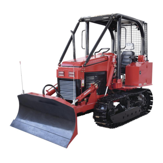
Intended Use The NorTrac 40XTD Bulldozer is incredibly strong and versatile, perfect for tough earth moving, ground leveling, road carving, and deforestation jobs for estate owners, landscape contractors, and builders. The 3- cylinder, diesel engine provides enough power to move tons of dirt, gravel, and other materials around your jobsite. - Page 5 Performance Part Property Specification Model 403F-E17T (Perkins) Type 3-cylinder, turbo-charged Cylinder bore 84 mm Piston stroke 100 mm Displacement 1.7 L Max. power 29 kw @ 2800 RPM Engine Max. torque 120 Nm @ 1800 RPM ± 5% Fuel Diesel Idling 800 r/min Direction of rotation...
-
Page 6: Important Safety Information
Part Property Specification 540 RPM @ engine 1812 RPM Two rotary speeds 1000 RPM @ engine 1772 RPM 35mm (13/8”), 6 splines Shaft diameter Fuel 28 l (7.4 gal) Engine oil sump 5.5 l (1.6 gal) Gearbox 11 l (2.9 gal) Service Capacity Hydraulic system 26 l (6.8 gal) - Page 7 ⚠WARNING WORK AREA SAFETY Inspect the work area before each use. Keep work area clean, dry, free of clutter, and well-lit. Cluttered, wet, or dark work areas can result in injury. Using the product in confined work areas may put you dangerously close to cutting tools and rotating parts.
-
Page 8: Specific Operation Warnings
perform its intended function. Replace damaged or worn parts immediately. Never operate the product with a damaged part. Do not use a product with a malfunctioning switch. Any power tool that cannot be controlled with the power switch is dangerous and must be repaired by an authorized service representative before using. ... - Page 9 • Wear proper hand and eye protection when searching for leaks. Never check for leaks with your hand while system is pressurized. Use wood or cardboard instead of hands • Relieve pressure on hydraulic system before servicing or disconnecting hoses. •...
-
Page 10: Grounding
The coolant is equipped with a heater which has a 3-prong plug. This needs to be grounded when plugged in to a 110-volt wall socket. Safety and Product Labels Ref.# Description Quantity NorTrac Decal Vehicle Reversing Warning Decal Crush Hazard (Hand) Warning Decal Crush Hazard (Body) Warning Decal Fall Hazard Warning Decal Entanglement Hazard Danger Decal... - Page 11 Ref.# Description Quantity Burn Hazard (Hot Coolant) Warning Decal #2 High-Pressure Fluid Hazard Warning Decal Hydraulic Filter Notice Decal ROPS Warning Decal Fire Hazard Danger Decal #2 Track Maintenance Warning Decal Start Up/Shut Down Procedure, Operational Warnings, Prop 65 Warning Decals Electrocution Hazard Danger Decal, Fall Hazard Warning Decals, Engine Notice Decal Diesel Fuel Decal Diesel Fuel Drain Decal...
- Page 12 Page 12 / 48...
- Page 13 Page 13 / 48...
-
Page 14: Before Each Use
Before Each Use ⚠WARNING • Always wear the proper protective equipment including ANSI Z87.1 compliant eye protection, hearing protection, steel toed boots, heavy-duty work gloves, and hard hat. • Follow all start up procedures before each use. • Before startup, check all fluids including engine oil, hydraulic oil, and coolant. •... - Page 15 Dozer Run-in 10 Minutes Run-in of the Engine at Idle Speed Start up the engine and increase the engine speed to raise coolant temperature and the engine oil pressure. Check if there is any oil or water leaking. Pay attention to the sound of the engine running and notice the indication of the ammeter, water thermometer, and the oil pressure gauge.
-
Page 16: Operating Instructions
Operating Instructions ⚠WARNING • Always wear the proper protective equipment including ANSI Z87.1 compliant eye protection, hearing protection, steel toed boots, heavy-duty work gloves, and hard hat. • Keep hands clear of all rotating parts and hot surfaces. • To prevent personal injury or property damage, retighten the nuts on driven wheel per working 50 hours. Torque is 160-180 Nm. - Page 17 • Do not operate without driveline shields that turn freely on driveline. • CRUSH AND DISMEMBERMENT HAZARD. Keep hands and feet away from track when engine is on. Shut engine off before servicing track. • ELECTROCUTION HAZARD. Serious injury or death can result from contact with electric lines. •...
- Page 18 Warm-up and Start-up Switch: Choke Control • When the key is in the OFF position, all circuits are off. • Turn clockwise to ‘H’ to warm up the engine. Continue to ‘ST’ to start it up (after warm-up). • When it’s turned clockwise to ON, all circuits, except warm-up and start-up circuit, are on (after start-up, the key is kept in this position).
- Page 19 Throttle Setting Switch & Lamp Switch (right side of meter) • The left switch defines the throttle adjustment range before the throttle control adjustment. Press and hold for 15 seconds to set the throttle. • The right switch controls the two head lights on the front cab. PTO Control Handle PTO control handle at left side of seat...
- Page 20 Engine Oil Level in the Engine Step 1. Find the oil dipstick. Step 2. Pull out the dipstick to check the oil lever before starting engine. Pull out the transmission fluid dipstick and check the transmission fluid at the floorboard before starting the engine.
- Page 21 Turn the water-trap tap semi-open. Water-trap Located on the lower left side of the diesel engine. Put the gearshift and PTO handle in the neutral position. Insert the key into the start-up ignition. Cautions During Start-up ⚠CAUTION • To prevent property damage, do not leave key in “H” position for more than 15 seconds. •...
- Page 22 Notice: The engine can only be started after pushing the clutch pedal completely in to connect the starting safety switch. Starting the Engine Warm-up the engine before using (when environment temperature is below 41° F or 5° C or the engine is cold).
- Page 23 R. Steering and Clutch Brake Pedal Pedal L. Steering and Auxiliary Brake Pedal Gearshift Main Gearshift Starting up after warm-up (when the environment temperature is less than 41° F or 5° C the engine is cold). 1. Press the clutch pedal all of the way in and turn the key to the ‘H’ position for 5-10 seconds. Then turn the key to the ‘ST’...
- Page 24 1. When driving, step down on one side of the steering and brake pedal (not completely) to disengage the steering partially. The bulldozer will turn to the same side. Step down on one side of the steering and brake pedal to the end to disengage the steering clutch completely and this side will brake completely causing the bulldozer to make a sharp turn or pivot.
- Page 25 be overloaded. (4). If the clutch slips or cannot engage completely or the steering lags, stop the bulldozer and address the concern. (5). While driving, do not put your foot on the clutch pedal or try to control the speed of the bulldozer using the clutch.
- Page 26 6-in-1 Rear Hydraulic Operation Output Handle Lever Rear 3-point PTO Hitch Operation Handle Six-blade Action Illustration Hitch system The hitch system control handle is located on right side of the 6-in-1 lever. When pulling the hitch handle back straight, the hitch rises. When pushing it forward, the hitch lowers. When the handle remains in the neutral position, the hitch floats between its present position and the highest position.
- Page 27 Take off the PTO Protection Cover Adjusting the Dozer’s Main Components This section instructs on how to check and adjust the main components of the chassis. To check and adjust the engine, refer to the 403F-E17T Perkins Operation and Maintenance Manual. Notice: The gearbox, main drive, and final drive of a new bulldozer have been adjusted by the manufacturer before delivery.
- Page 28 The normal clearance between the surfaces of the clutch release fingers and the clutch release bearing is 2- 3mm (see Fig. 3). When disengaging the clutch, a force is applied on the clutch pedal to eliminate the clearance. The moving distance of the top of the pedal is called “free play”. It should be 20-30mm. Continue to press in the pedal, the release rocker moves forward until it reaches the stopper bolt screw.
- Page 29 Fig 4. Fig. 5 Adjusting the Spiral Bevel Pinion Shaft After pre-tightening the spiral bevel pinion shaft’s tapered roller bearing, the measured total friction torque of the spiral pinion shaft should be 1.0~1.5 mm (see Fig. 4). Adjusting the Pair of Spiral Bevel Gears The two spiral bevel gear adjustments should be started after 1-2 minutes of testing in positive and negative directions, running when there is no oil in the gearbox case.
- Page 30 Adjusting the Spiral Bevel Pinion Shaft After pre-tightening the tapered roller bearing of the spiral bevel pinion shaft, the measured total friction torque of the spiral pinion shaft should be 1.0-1.5mm (see Fig. 6). Adjusting the Pair of Spiral Bevel Gears Begin adjusting the pair of spiral bevel gears after 1-2 minutes of testing in positive and negative directions, running when there is no oil in the gearbox case.
- Page 31 Fig. 6 The imprint of spiral bevel gears pair adjustment will be implemented by increasing or decreasing the number of shims of the spiral bevel pinion shaft and nuts adjustment on both sides of the bevel gear. At the same time, the adjusting nuts are also used to pre-tighten the tapered roller bearing of the main drive shaft.
- Page 32 The steering is integrated with the brake. Controlling the brake pedals also controls the steering clutches sequentially with the same pedals. Following steps instruct the operator on how to adjust. Screw in the two adjusting bolts until tight and then screw out the bolts for 4/5 to 1 round. The clearance between the brake and the hub should be 1.2-1.5mm.
-
Page 33: After Each Use
Fig. 9 After Each Use ⚠WARNING • Follow all shutdown procedures after each use. • NEVER STORE THE MACHINE WITH THE BLADE ABOVE GROUND! Always lower the blade to the ground and release the hydraulic pressure using the control levers. •... - Page 34 general condition of any tool be examined before it is used. Keep your dozer in good repair. Keep handles dry, clean, and free from oil and grease. Also refer to the engine manufacturer’s instruction manual for additional information about engine maintenance. The following chart is based on a normal operation schedule. Maintenance Maintenance Point Interval...
- Page 35 Maintenance Maintenance Point Interval • Replace the engine oil filter. • Check the fan belt tension (press down approximately 15mm with index finger). Radiator Fan belt To adjust the tension of the belt, loosen the bolts. • Maintain every 1000 hours. •...
- Page 36 Maintenance Maintenance Point Interval Air filter Screw off the lid and replace with a new air filter. • Replace the oil and oil filter. Replace with a new oil filter. • Replace the lubricant in the gearbox. Step 1. Screw off the four bolts on the magnetic cover and release the gear oil.
- Page 37 Maintenance Maintenance Point Interval Step 1. Open the plug with the hex wrench and empty the oil from the final drive case. Step 2. Put the sealing washer on the plug and then insert the plug. Step 3. Screw off the plug tap and fill the oil into tank.
- Page 38 Maintenance Maintenance Point Interval • Clean the air filter. (Dusty environments require daily maintenance.) • Change the engine oil filter (new or overhauled dozer only). • Change the hydraulic oil filter • Change the fuel filter (new or overhauled dozer only). 50-Hour •...
-
Page 39: Troubleshooting
Lubrication Points Fig. 10 Troubleshooting Use the table below to troubleshoot problems before contacting service personnel or your local dealer. If the problem continues after troubleshooting, call your local dealer for assistance. 1. Clutch Failure Possible Cause Corrective Action There is some grease or oil on the disc Replace and repair surface. - Page 40 Failure Possible Cause Corrective Action Axial force due to open tape of gear Replace the gear. teeth. Inspect the gearshift After shifting gears, drive and driven travel and the gears aren’t meshed completely. positions of gears. Teeth direction is incorrect or teeth Replace the gear.
- Page 41 3. Brake Failure Possible Cause Corrective Action There is grease or oil on brake Replace. Brakes are not bands. Brake bands are excessively worn. Replace. sensitive enough. The free stroke of brake is Re-adjust. excessive. The free stroke is too small. Re-adjust.
- Page 42 Possible Cause Corrective Action The implement is not fit for the Choose the proper bulldozer. implement. 6. Electrical System Failure Possible Cause Corrective Action • The battery is in poor condition. • Recharge or repair. A cable joint is loose. •...
- Page 43 Fig. 11 Fig. 12 43 / 48...
-
Page 44: Parts Diagram
Parts Diagram Parts List Reference Part Number Part Description Quantity Engine Tilt Cylinder Six-action Blade Angling Cylinder Idler Track Roller Track Chain Sprocket Hitch Linkage Gearshift Levers Seat Hitch Control Levers 6-in-1 Control Lever Dashboard Steering and Braking Pedals Lift Cylinder Clutch Pedal READ &... -
Page 45: Replacement Parts
Replacement Parts • For replacement parts and technical questions, please call Customer Service at 1-800-521-0438. • Not all product components are available for replacement. The illustrations provided are a convenient reference to the location and position of parts in the assembly sequence. •... -
Page 46: Limited Warranty
Disclaimer of Consequential Damage In no event will NorTrac or NTE Company, Inc. be liable for any loss of income, loss of time or use of the product, transportation, hiring of alternative services, commercial loss or any other incidental, consequential, indirect, or special damages and / or expenses. - Page 47 Distributed by: Northern Tool & Equipment Company, Inc. Burnsville, Minnesota 55306 www.northerntool.com Made in China Page 47 of 48...
Need help?
Do you have a question about the 40XTD and is the answer not in the manual?
Questions and answers