Intel ISP1100 Product Manual
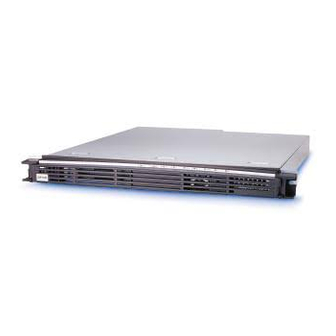
Internet server
Hide thumbs
Also See for ISP1100:
- Quick start manual (32 pages) ,
- Installation manual (24 pages) ,
- Installation manual (20 pages)

Related Manuals for Intel ISP1100


Summary of Contents for Intel ISP1100
-
Page 1: Product Guide
® Intel ISP1100 Internet Server Product Guide ® A Guide for Technically Qualified Assemblers of Intel Identified Subassemblies/Products Order Number: A10528-001... - Page 2 Disclaimer Intel Corporation (Intel) makes no warranty of any kind with regard to this material, including, but not limited to, the implied warranties of merchantability and fitness for a particular purpose. Intel assumes no responsibility for any errors that may appear in this document.
-
Page 3: Table Of Contents
Safety Compliance... 24 Electromagnetic Compatibility (EMC)... 24 Tools and Supplies Needed... 24 Removing the Server From the Rack... 24 Installing the Server in the Rack ... 25 Removing the Cover... 26 Replacing the Cover ... 26 Removing the Processor ... 27 Removing the Processor Heat Sink ... - Page 4 Preparing for the Upgrade ... 63 Performing the Upgrade... 65 Recovering the BIOS ... 65 4 Solving Problems Resetting the System ... 68 Initial System Startup... 68 Checklist ... 68 Running New Application Software... 69 Checklist ... 69 Intel ISP1100 Internet Server Product Guide...
- Page 5 Server Board Connectors and Components ... 9 Front Panel Controls, Connectors, and Indicators... 10 Back Panel Connectors ... 10 Removing/Installing the Server in the Rack ... 25 Removing/Replacing the Cover ... 26 Removing the Processor Heat Sink ... 27 Removing the Processor Chip ... 28 Removing the Processor Fan ...
- Page 6 Diskette Configuration Submenu ... 59 Event Log Configuration Submenu ... 59 Security Menu... 60 Boot Menu ... 60 System Management Menu ... 62 Exit Menu ... 63 Beep Codes... 75 Error Messages Description... 76 Intel ISP1100 Internet Server Product Guide...
-
Page 7: Description
1 Description System Components Figure 1 shows the location of the major system components in the Intel PCI Add-in Card Slots PCI Riser Card C. Server Board D. Power Supply 1-Inch Hard Drive Bracket 1-Inch Hard Drive Bracket G. 3.5-Inch Diskette Drive H. -
Page 8: Server Board Features
82371EB PCI ISA IDE Xcelerator (PIIX4E) Pro/100+ Server ( 82559) Ethernet controllers ® † interfaces for keyboard and mouse ® /AMI BIOS ® E28F008S585 8-Mbit boot block flash memory † Intel ISP1100 Internet Server Product Guide ™ processor in a... -
Page 9: Server Board Connectors And Components
Server Board Connectors and Components Figure 2 shows the locations of the server board connectors and components. Wake on LAN Connector Speaker PCI Riser Sideband and PCI Bus Connectors SMSC I/O Controller Battery Intel Pro/100+ Server (82559) Ethernet Controllers SCSI LED Connector... -
Page 10: Controls, Connectors, And Indicators
Controls, Connectors, and Indicators Front Panel Figure 3 shows the locations of the server front-panel controls, connectors, and indicators. Power LED Indicator (Green) System Fault LED Indicator (Amber) C. Hard Drive Activity LED Indicator (Green) D. LAN 1 Activity LED Indicator (Yellow) -
Page 11: Processors
Processors The server board supports a single Intel Pentium III processor or Celeron processor that plugs into a PGA370 socket connector that secures the processor chip with a zero-insertion-force (ZIF) arm. The host bus speed (66 MHz or 100 MHz) is automatically selected. Table 2 lists the processors supported by the server board. -
Page 12: Supported Memory Characteristics
Unbuffered DIMMs of the following sizes: 16 MB, 32 MB, 64 MB, 128 MB and 256 MB for a total memory size of 1 GB. Registered DIMMs of the following sizes: 64MB, 128Mb and 256MB for a maximum memory size of 1 GB. Only non-stacked DIMMs are supported because of a server board space constraint. Table 3. -
Page 13: Chipset
66 MHz or 100 MHz SDRAM. Chipset The Intel 82440BX AGPset consists of the Intel 82443BX PAC and the Intel 82371EB PIIX4E bridge chip. The PAC provides an optimized DRAM controller. The PAC’s accelerated graphics port (AGP) interface is not used. The I which is a highly integrated PCI ISA IDE Xcelerator Bridge. -
Page 14: Ide Support
The server board has two independent bus-mastering IDE interfaces that support: 1. ATAPI devices (such as CD-ROM drives). 2. ATA devices using the transfer modes listed in the Intel ISP1100 Internet Server Technical Product Specification. The BIOS supports logical block addressing (LBA) and extended cylinder head sector (ECHS) translation modes. -
Page 15: I/O Controller
I/O Controller The FDC37B807 I/O controller from SMSC is an ISA Plug and Play-compatible, multifunctional I/O device that provides the following features (see Chapter 13 in the Intel ISP1100 Internet Server Technical Product Specification for Plug and Play specification information): Two serial ports. -
Page 16: Keyboard And Mouse Interface
Keyboard and Mouse Interface The PS/2 keyboard and mouse connectors are located on the server back panel. The +5 V lines to these connectors are protected with a PolySwitch the connection after an overcurrent condition is removed. The keyboard controller contains the AMI keyboard and mouse controller code, provides the keyboard and mouse control functions, and supports password protection for power on/reset. -
Page 17: Scsi Hard Drive Led Connector
LED as the IDE controller. This connector can be connected to the LED output of the add-in controller card (see Chapter 13 in the Intel ISP1100 Internet Server Technical Product Specification for the location and pinouts of the SCSI hard drive LED connector). -
Page 18: Wake On Ring/Resume On Ring
A and B. For internal modems, a cable must be routed from the modem to the Wake on Ring connector. See “Server Board Connectors and Components” for the location and definition of the Wake on Ring connector. Resume on Ring The operation of Resume on Ring can be summarized as follows: 1. -
Page 19: Smi And Nmi Routing
H_SMI input or not. For details on the fault conditions that cause SMI to occur, consult the data sheets of the SMI source ICs. The SMI routing on the server board is described in Table 6. Note that some PIIX4 inputs have several sources. Schematic signal names are in parenthesis. -
Page 20: Fan Support
Fan Support The server board has five fan connectors. The functions of the fan connectors are described in Table 7. Table 7. Fan Connector Descriptions Connector Function Fan 1 (J35) Supports fan speed sensing for fans with tachometer outputs. Connector supports variable fan speed. -
Page 21: Removing/Installing Server Components
2 Removing/Installing Server Components This chapter provides procedures for removing and installing replaceable and/or upgradable components in the Intel ISP1100 Internet Server. Before performing the procedures, be sure to familiarize yourself with the following “Before You Begin” information. Before You Begin... - Page 22 Wear an antistatic wrist strap and attach it to a metal part of the server. Touch the metal on the server chassis before touching the server components. Keep part of your body in contact with the metal server chassis to dissipate the static charge while handling the components.
-
Page 23: Rackmount Precautions
20 amperes of protection, you must provide supplemental protection for the server. If more than one server is installed in the rack, the power source for each server must be from a separate branch circuit. CAUTIONS TEMPERATURE: The operating temperature of the server, when installed in an equipment rack, must not go below 5 °C (41°F) or rise above 35 °C... -
Page 24: Safety And Regulatory Requirements
5. Antistatic wrist strap and conductive foam pad (recommended) Removing the Server From the Rack This procedure describes how to remove the server from the rack. Before proceeding, be sure you are thoroughly familiar with the information in “Before You Begin” at the front of this chapter. -
Page 25: Installing The Server In The Rack
Installing the Server in the Rack This procedure describes how to install the server in the rack. Before proceeding, be sure and familiarize yourself with the “Rackmount Precautions” information in the “Before You Begin” section at the front of this chapter. Refer to Figure 5 while performing this procedure. -
Page 26: Removing The Cover
Removing the Cover This procedure describes how to remove the cover from the server. Before proceeding, be sure you are thoroughly familiar with the information in “Before You Begin” at the front of this chapter. Refer to Figure 6 while performing this procedure. -
Page 27: Removing The Processor
Removing the Processor This procedure describes how to remove the processor on the server board. Before proceeding, be sure you are thoroughly familiar with the information in “Before You Begin” at the front of this chapter. WARNING If the server has been running recently, the processor chip, heat sink, and adjacent components will be hot. -
Page 28: Removing The Processor Chip
Perform this procedure to remove the processor chip from the socket. Refer to Figure 8 while performing this procedure. 1. Face the front of the server and grasp the end of the zero-insertion-force (ZIF) arm (A) on the left side of the processor socket. -
Page 29: Removing The Processor Fan (If Applicable)
This procedure describes how to remove the processor fan from a replacement processor. Due to space constraints, the server will not accommodate a processor with a fan mounted on the heat sink. Sufficient cooling is provided in the server without the processor fan. -
Page 30: Installing The Processor Chip
2. Swing the ZIF arm up until it stops in the straight up position. The processor socket is now unlocked. 3. Face the front of the server and orient the processor chip (C) with the notch (D) in the upper left corner of the processor socket (E). -
Page 31: Installing The Processor Heat Sink
4. With the front of the clamp below the top edge of the heat sink, press down on the front of the clamp (G) until it snaps onto the socket tab (H). Figure 11. Installing the Processor Heat Sink Removing/Installing Server Components OMO9432... -
Page 32: Removing The Dimm Boards
Refer to Figure 12 while performing this procedure. 1. Grasp the ejector lever (A) on one end of the DIMM board and push down on the lever until the end of the board edge connector (B) just lifts out of the server board socket (C). CAUTION... -
Page 33: Installing The Dimm Boards
2. Firmly press the DIMM board straight down and all the way into the server board socket. 3. Make sure the DIMM board is locked in by pressing the levers (C) on each end of the server board socket into the mating notches (D) on each edge of the DIMM board. -
Page 34: Removing The Hard Drive(S)
2. Grasp the back of the drive and lift until the drive mounting bracket (B) releases from the two snaptop standoffs (C). 3. Slide the mounting bracket back to release the tabs from the slots (D) in the server front panel. 4. Remove the mounting bracket and drive from the drive bay. -
Page 35: Installing The Hard Drive(S)
Installing the Hard Drive(s) This procedure describes how to install hard drives in the server drive bays. Before proceeding, be sure you are thoroughly familiar with the information in “Before You Begin” at the front of this chapter. Installing the Hard Drive in the Mounting Bracket Perform this procedure to install the hard drive in the mounting bracket. -
Page 36: Installing The Hard Drive In The Drive Bay
1. Connect the power and data cables to the back of the drive (D). 2. Position the drive in the server drive bay so that the end of the bracket with the tabs (A) is facing the server front panel. -
Page 37: Removing The 3.5-Inch Diskette Drive
2. Use a Phillips screwdriver and remove the three screws (B) that secure the mounting bracket (C) and drive to the server chassis (two on one side and one on the other). 3. Remove the drive mounting bracket and drive. -
Page 38: Installing The 3.5-Inch Diskette Drive
Installing the 3.5-inch Diskette Drive This procedure describes how to install the 3.5-inch diskette drive in the server drive bay. Before proceeding, be sure you are thoroughly familiar with the information in “Before You Begin” at the front of this chapter. -
Page 39: Installing The 3.5-Inch Diskette Drive In The Drive Bay
2. Place the mounting bracket and drive in the server chassis and align the three screw holes (A) in the mounting bracket (two on one side and one on the other) with the mating holes in the server chassis. -
Page 40: Removing The Pci Add-In Card(S)
Removing the PCI Add-in Card(s) This procedure describes how to remove the PCI add-in card(s) from the server board. Before proceeding, be sure you are thoroughly familiar with the information in “Before You Begin” at the front of this chapter. -
Page 41: Removing The Riser And Add-In Card(S)
Removing the Riser and Add-in Card(s) Perform this procedure to remove the riser and add-in card(s) from the server board. Refer to Figure 21 while performing this procedure. CAUTION Do not attempt to remove an add-in card without first removing the riser card from the server board. -
Page 42: Removing The Add-In Card(S) From The Riser
2. Firmly hold the riser card while gently rocking and pulling the add-in card until the add-in card releases from the riser connector. 3. Remove the add-in card from the riser connector. Figure 22. Removing the Add-in Card(s) from the Riser OMO9460 Intel ISP1100 Internet Server Product Guide... -
Page 43: Installing The Rear I/O Filler Panel(S)
Perform this procedure to install rear I/O filler panels in any unused expansion slots. Refer to Figure 23 while performing this procedure. 1. Align the filler panel retention bracket (A) with the two mating screw holes on top of the server back panel. -
Page 44: Installing Pci Add-In Card(S)
If applicable, check that the add-in card jumpers or switches are set according to the manufacturer’s instructions before proceeding. Removing the Riser Card Perform this procedure to remove the riser card from the server board. Refer to Figure 24 while performing this procedure. NOTE This procedure assumes that the PCI add-in cards have been removed from the server chassis as described in the previous “Removing the PCI Add-in... - Page 45 Removing/Installing Server Components...
-
Page 46: Installing The Add-In Card(S) On The Riser
(12.06 cm) long. The low-profile card fits into the right expansion slot (when facing the front of the server) and the standard card fits in the left slot. 1. Align the add-in card edge connector (A) with the proper riser connector (B). For example: 2. -
Page 47: Removing The Rear I/O Filler Panel(S)
1. Use a Phillips screwdriver and remove the two screws (A) securing the filler panel retention bracket (B) to the top edge of the server back panel. 2. Remove the retention bracket. 3. Remove the filler panel (C) from the expansion slot for the add-in card(s) you are installing. -
Page 48: Installing The Riser And Add-In Card(S)
Perform this procedure to install the riser and add-in card(s) in the server PCI expansion slots. Refer to Figure 27 while performing this procedure. 1. Align the riser card edge connector (A) with the mating riser connector on the server board. (The connectors are keyed to mate in only one direction.) -
Page 49: Replacing The Back-Up Battery
(RTC) in the absence of AC power. The lithium battery lasts for up to 10 years; but when it starts to lose voltage the server settings stored in the CMOS RAM in the RTC (for example, the date and time) may be incorrect. Contact your supplier or dealer for a list of approved devices. -
Page 50: Replacing The Lithium Back-Up Battery
1. Remove the server cover as described in the “Removing the Server Cover” procedure. 2. Insert the tip of a flat bladed screwdriver (A), or equivalent, under the tab in the plastic battery retainer (B). 3. Gently push down on the screwdriver to lift the battery (C). -
Page 51: Power Up The Server
Rating: Power cords must be rated for available AC voltage and have a current rating at least 125% of the server current rating. (Refer to the Intel ISP1100 Internet Server Technical Product Specification included on the CD-ROM shipped with the server for power requirement information.) -
Page 52: Powering Up The Server
Grasp the tab (B) at each end of the hinged bezel door. b. Gently pull the tabs out and down to swing open the hinged bezel door. 4. Press the Power switch (C) to apply power to the server and notice that the green LED power indicator (D) is lit. - Page 53 Removing/Installing Server Components...
-
Page 54: Configuration Software And Utilities
Power-On Self-Test (POST) Each time you turn on the system, POST starts running. POST checks the server board, processor, memory, keyboard, and most installed peripheral devices. During the memory test, POST displays the amount of memory that it is able to access and test. The length of time needed to test memory depends on the amount of memory installed. -
Page 55: Using Bios Setup
<Tab> key to move between the hour, minute, and second fields. Configuration Software and Utilities System Security Boot Management Set passwords Selects boot Configures and security options and server features power management supply features such control as console redirection Exit Saves or discards changes to Setup... -
Page 56: Main Menu
Selects which language the BIOS displays. Allows the user to turn error reporting on or off if the system and all memory installed support ECC (Error Correction Code). Sets the system time. Sets the system date. Intel ISP1100 Internet Server Product Guide Exit... -
Page 57: Advanced Menu
Advanced Menu The menu bar is shown below. Main Advanced Table 13 shows the Advanced menu. This menu configures advanced features that are available through the chipset. Table 13. Advanced Menu Feature Options Boot See Table 14 Configuration Peripheral See Table 15 Configuration See Table 16 Configuration... -
Page 58: Ide Configuration Menu
Enables or disables the LBA mode control. Specifies the number of sectors per block for transfers in a single interrupt from the hard drive to memory. Check the hard drive’s specification for optimum setting. Intel ISP1100 Internet Server Product Guide continued... -
Page 59: Diskette Configuration Submenu
Table 17. IDE Configuration Submenu (continued) Feature Options PIO Mode Auto (default) Ultra DMA Disabled (default) Mode 0 Mode 1 Mode 2 Mode 3 Mode 4 Table 18. Diskette Configuration Submenu Feature Options Diskette Disabled Controller Enabled (default) Floppy A Not Installed 360KB 5.25”... -
Page 60: Security Menu
OEM logo instead of POST messages. Allows the BIOS to skip certain tests while booting. This decreases the time needed to boot the system. Allows the BIOS to scan the Flash ROM for user binaries. Intel ISP1100 Internet Server Product Guide Exit Exit continued... - Page 61 Configures the boot sequence from the available devices. IDE-HDD = Hard disk drive. Intel UNDI, PXE-2.0 = Network boot using PXE. ARMD-FDD = ATAPI removable device-floppy disk drive. SCSI = If a SCSI device is installed, it will appear as one of the possible boot devices with the name of device.
-
Page 62: System Management Menu
System Management Menu The menu bar is shown below. Main Advanced Table 22 shows the System Management menu. This menu sets server management features. Table 22. System Management Menu Feature Options Serial Port Disabled COM1 3F8 IRQ4 (default) COM2 2F8 IRQ3... -
Page 63: Exit Menu
Exit Menu The menu bar is shown below. Main Advanced Table 23 shows the Exit menu. This menu exits the Setup program – saving, discarding, and loading default settings. Table 23. Exit Menu Feature Options Exit Saving Changes No options Exit Discarding No options Changes... -
Page 64: Obtaining The Upgrade Utility
You can upgrade to a new version of the BIOS using the new BIOS files and the BIOS upgrade utility, iFLASH.EXE. You can obtain the BIOS upgrade file and the iFLASH.EXE utility through your computer supplier or from the Intel Customer Support website: http://www.intel.com/isp... -
Page 65: Performing The Upgrade
7. To extract the BIOS.EXE file and type: BIOS.EXE BIOS A: 8. Press <Enter> 9. The floppy disk now holds the BIOS upgrade and recovery files. Performing the Upgrade 1. Boot the computer with the floppy disk in drive A. The BIOS upgrade utility screen appears. 2. - Page 66 12. Set the BIOS configuration jumper to pins 1-2. 13. Replace the computer cover. Leave the upgrade disk in drive A and turn on the computer. 14. Continue with the BIOS upgrade (see “Upgrading the BIOS” on page 54). Intel ISP1100 Internet Server Product Guide...
- Page 67 Configuration Software and Utilities...
-
Page 68: Solving Problems
Is AC power available at the wall outlet? q Are all integrated components from the tested components lists? Check the tested memory, and chassis lists, as well as the supported hardware and operating system list on the Intel Customer Support website: http://www.intel.com/isp Press: <Ctrl+Alt+Del>... -
Page 69: Running New Application Software
Running New Application Software Problems that occur when you run new application software are usually related to the software. Faulty equipment is much less likely, especially if other software runs correctly. Checklist q Does the system meet the minimum hardware requirements for the software? See the software documentation. -
Page 70: More Problem Solving Procedures
Once the system boots up, the operating system prompt appears on the screen. The prompt varies according to the operating system. If the operating system prompt does not appear, see “No Characters Appear on Screen” on page 71. Intel ISP1100 Internet Server Product Guide... -
Page 71: Specific Problems And Corrective Actions
Is the onboard video controller enabled? If you are using an add-in video controller board, do the following: 1. Verify that the video controller board is fully seated in the server board connector. 2. Reboot the system for changes to take effect. -
Page 72: Characters Are Distorted Or Incorrect
Is the diskette drive activity light always on? If so, the signal cable may be plugged in incorrectly. If the problem persists, there may be a problem with the diskette drive, server board, or drive signal cable. Contact your service representative or authorized dealer for help. -
Page 73: Hard Disk Drive Activity Light Does Not Light
SCSI device, is in use. This LED does not display CD-ROM activity. Cannot Connect to a Server q Make sure you are using the drivers that are shipped on the system Configuration Software CD for the onboard network controller. -
Page 74: Problems With Network
Try a different copy of the software to see if the problem is with the copy you are using. q Make sure all cables are installed correctly. q Verify that the server board jumpers are set correctly. See Chapter 1. †... -
Page 75: Bootable Cd-Rom Is Not Detected
q If other software runs correctly on the system, contact your vendor about the failing software. If the problem persists, contact the software vendor’s customer service representative for help. Bootable CD-ROM Is Not Detected Check the following: q Is the BIOS set to allow the CD-ROM to be the first bootable device? Error and Informational Messages When you turn on the system, POST displays messages that provide information about the system. -
Page 76: Error Messages Description
The keyboard has a timing problem. Make sure a Keyboard Controller AMIBIOS is installed. Set Keyboard in Advanced Setup to Not Installed to skip the keyboard POST routines. KB/Interface Error There is an error in the keyboard connector. continued Intel ISP1100 Internet Server Product Guide... - Page 77 Table 25. Error Messages Description (continued) Error Message Description No ROM BASIC Cannot find a proper bootable sector on drive A:, C:, or CD-ROM drive. AMIBIOS cannot find ROM Basic. Parity error in memory installed on an adapter card in an expansion slot. The format is: Off Board Parity Error OFF BOARD PARITY ERROR ADDR = (XXXX)
-
Page 78: Index
43, 46 hard drive installation, 35 installation in drive bay, 36 installation in mounting bracket, 35 removal, 34 hardware monitor, 16 heat sink installation, 31 removal, 27 hot key option, quick reference, 53 Intel ISP1100 Internet Server Product Guide... - Page 79 22 power on/off, switch does not turn off AC power, 22 power supply, hazardous conditions, 22 powering up the server, power cord requirements, 50 problems after running new application software, 68 after system has been running correctly, 68...
- Page 80 Wake on Ring, 18 Warning components may be hot, 27 disconnect power cords, cables, 22 dispose of lithium battery safely, 48 no user-serviceable parts, power supply, 22 power on/off switch, 22 warnings and cautions, 21 Intel ISP1100 Internet Server Product Guide...
- Page 81 Index...
Need help?
Do you have a question about the ISP1100 and is the answer not in the manual?
Questions and answers