Advertisement
Advertisement
Table of Contents

Related Manuals for EURO EG90GFSX


Summary of Contents for EURO EG90GFSX
- Page 1 FREESTANDING COOKER AND CERAMIC GLASS OPERATING AND INSTALLATION INSTRUCTIONS models: EG90GFSX - EG900GDSX - EP90DMSX - EE900GSXS 461308131_001 05/2012...
-
Page 2: Table Of Contents
The appliance was designed and made in accordance with the International standards listed below: =>IEC 60 335-1 and IEC 60 335-2-6 (electrical) plus relative amendments The appliance complies with the prescriptions of the International Directives as below: Electrical safety (BT). Electromagnetic compatibility (EMC) Gas safety. -
Page 3: Important Notes And Precautions For Use
IMPORTANT NOTES AND PRECAUTIONS FOR USE You have purchased one of our products for which we • DOMESTIC USE ONLY thank you. We are confident that this new appliance, There are a few basic rules that must be observed modern, functional and practical, made with top when using the appliance: quality materials, will meet all your demands. -
Page 4: Description Of The Appliance
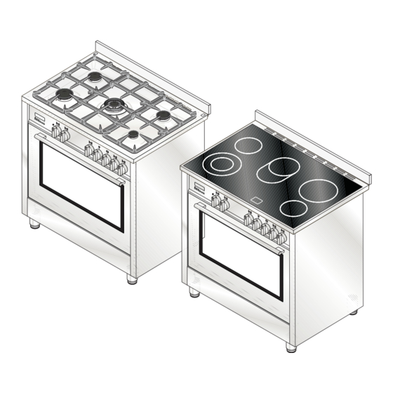
DESCRIPTION OF THE APPLIANCE The oven walls are fitted with various guide bars or PRESENTATION runners (fig. 1) on which the following accessories can Our cooker is fitted with a fully gas hotplate. This be placed. Supply and quantities vary from model innovative burner hotplate offers you more scope and to model (fig. - Page 5 DESCRIPTION OF THE APPLIANCE DESCRIPTION OF THE CONTROLS HOB GAS BURNER KNOB (A) By rotating the knob in an anticlockwise direction, the following symbols appear: = Closed position = “Full on” position = “Reduced rate or Low” position GAS OVEN/ELECTRIC GRILL THERMOSTAT KNOB (B) By rotating the knob in an anticlockwise direction, the following functions appear: = Closed position...
- Page 6 DESCRIPTION OF THE APPLIANCE RED WARNING LIGHT When lit it indicates that the electric grill or one of the � oven electric components is on. YELLOW WARNING LIGHT When lit it indicates that either the electric oven or electric grill is working. While the oven is being used the light will switch off when the set temperature is reached.
- Page 7 DESCRIPTION OF THE APPLIANCE TIMER (I) To set cooking time, first wind the timer up by turning it completely once from left to right and then back to the number of minutes you want. The timer will ring when the set time has elapsed.
-
Page 8: Description Of The Appliance
DESCRIPTION OF THE APPLIANCE ELECTRONIC PROGRAMMER � The programmer can select the following functions: � - Clock (set by keys 2 and 3) � � � - Minute counter (set by key 1) � - Cooking time (set by key 2) - End of cooking (set by key 3) - Manual operation mode... -
Page 9: Instructions For The User
INSTRUCTIONS FOR THE USER HOB: GENERAL NOTES ON SAFETY ABNORMAL OPERATION Any of the following are considered to be abnormal • When using the burners, do not leave the appliance unsupervised. Ensure that children and the infirm operation and may require servicing: do not play with the appliance. - Page 10 INSTRUCTIONS FOR THE USER ����������� • Never cover the base of the oven or the oven shelf with aluminium foil or other materials, as this creates a fire hazard. • When grilling always put a little water in the grill pan.
- Page 11 INSTRUCTIONS FOR THE USER would melt, sticking to the hob. GENERAL INFORMATION AND INSTRUCTIONS FOR USING CERAMIC GLASS HOBS N.B.: Using the glass scraper, push immediately away • Ceramic glass is a natural product and, like any other from the cooking zone, any pieces of tin foil or plastic material in ceramic, can have an uneven surface.
- Page 12 INSTRUCTIONS FOR THE USER OVEN: GENERAL SAFETY INSTRUCTIONS WHAT TO DO THE FIRST TIME YOU USE THE OVEN • Remove all protective wrapping materials from the • Do not leave the oven unsupervised during use. Ensure that children and the infirm do not play with appliance and labels from the oven door.
- Page 13 INSTRUCTIONS FOR THE USER Be sure to remove the enamelled grill tray when the • HOW TO USE GAS OVEN oven is in use. It is not intended to be used for baking or roasting purposes and it can interfere with heat The oven burner can be fitted with a safety distribution in the oven.
- Page 14 INSTRUCTIONS FOR THE USER HOW TO USE THE MULTIFUNCTION OVEN CONVETIONAL GRILL COOKING Turn the selector knob to the symbol and adjust the DEFROSTING AT ROOM TEMPERATURE thermostat knob to the desired temperature. Turn the selector knob to the symbol and place the Selecting this function the top central heating element food you want to defrost inside the oven.
- Page 15 INSTRUCTIONS FOR THE USER TIME AND TEMPERATURE CHART The above table gives guidelines for cooking a range of different foods, individual food, or personal preferences may slightly vary the oven position, temperature and cooking time from those suggested. Please note that: •...
- Page 16 INSTRUCTIONS FOR THE USER USEFUL COOKING TIPS Meat: • If, when cooking meat, the time needed is more than 40 minutes, turn the oven off 10 minutes Cakes and bread: before the end of cooking time to exploit the • Heat the oven for at least 15 minutes before you residual heat (energy saving).
- Page 17 INSTRUCTIONS FOR THE USER the glass. NEVER use sponges or abrasive products, CLEANING AND MAINTENANCE and aromatic or aliphatic solvents to remove stains or adhesives on the painted or stainless steel surfaces. • Prior to any maintenance work or cleaning, disconnect the appliance from the electricity mains.
-
Page 18: Instructions For The User
INSTRUCTIONS FOR THE USER HOW TO CLEAN THE INNER OVEN DOOR GLASS One of the features of our cookers is that the inner oven door glass can be easily removed for cleaning without the aid of specialized personnel. Just open the oven door and remove the support securing the glass (fig. -
Page 19: Troubleshooting
TROUBLESHOOTING Some problems can be caused either as the results of simple maintenance operations or by incorrect selection of settings. Prior to contacting a Service Centre please check the following chart. PROBLEM REMEDY The appliance is not working • Make sure the gas cock is open •... - Page 20 INSTRUCTIONS FOR THE INSTALLER POSITION (fig. 14) LEVELLING THE COOKER The appliance should be positioned in good light and • Adjustable feet, to be fitted to the appliance, which free from draughts. Any adjoining wall surface situated allow the height of the cooker to be aligned with within 200 mm from the edge of any hob burner must be other kitchen furniture This can be done by means a suitable non-combustible material for a height of 150...
-
Page 21: Assembly Instructions
INSTRUCTIONS FOR THE INSTALLER SECURING THE COOKER TO WALL (fig. 18) COOKER IN FINAL POSITION PULL BOTH SAFETY CHAINS AND SECURE THEM TO THE INSIDE OF Note:- The installation of the chain provided THE CUPBOARD WITH TWO SCREWS ON EACH is for safety reasons, it must be installed as SAFETY CHAIN. -
Page 22: Gas Connection
INSTRUCTIONS FOR THE INSTALLER permanent deformation and should be able to be GAS CONNECTION inspected along its entire length. Unions compatible This appliance shall be installed only by authorised with the hose fittings must be used and connections personnel and in accordance with the manufacturer’s tested for gas leaks. - Page 23 INSTRUCTIONS FOR THE INSTALLER ELECTRICAL CONNECTION TAPS (fig. 19) All gas taps are male cone type with only one way of The electrical connection must be carried out in passage. The adjustment screw (V) is on the side of accordance with the current standards and laws the stem.
- Page 24 INSTRUCTIONS FOR THE INSTALLER Hot Plate Ignition Failure GAS CONVERSIONS • Check alignment of burner holes to electrode. • Check aeration sleeve for adjustment for gas type, REPLACING THE INJECTORS location and ambient conditions. Our burners can be adapted to different types of gas •...
- Page 25 INSTRUCTIONS FOR THE INSTALLER MAINTENANCE �� Prior to any maintenance work or changing parts, disconnect the appliance from the gas �� and electricity power sources. Servicing must only be carried out by authorised personnel. REPLACING THE TAPS Proceed in the following way when replacing a tap • Remove pan supports, burner heads.
-
Page 26: Instructions For The Installer
INSTRUCTIONS FOR THE INSTALLER MAINTENANCE REPLACING THE ELECTRICAL COMPONENT Prior to any maintenance work or changing • The rear protection will have to be removed in parts, disconnect the appliance from the gas order to change the electrical heating elements, and electricity power sources. - Page 27 7.5 mm open Oven Natural 1.00 15.1 7.5 mm open ELECTRICAL COMPONENTS - NOMINAL DATA DESCRIPTION EG90GFSX EG900GDSX - EP90DMSX EE900GSXS Lower heating element of the oven 2100 W 2100 W Top heating element of the oven-grill 2000 + 2200 W...
-
Page 28: Technical Features
TECHNICAL FEATURES Model cooker EG900GDSX... - Page 29 TECHNICAL FEATURES Model cooker EP90DMSX...
- Page 32 SPACE FOR DATA LABEL 461308131_001 05/2012...
Need help?
Do you have a question about the EG90GFSX and is the answer not in the manual?
Questions and answers
MY OVEN IS NOT WORKING.THERE IS POWER TO THE TIME CLOCK ,AS THIS IS ON . ANY SUGGESTIONS
For a EURO EG90GFSX oven that has power to the time clock but is not working, follow these troubleshooting steps:
1. Check the oven ignition system:
- Ensure the electrode lead is not touching or "earthing" against the cabinet.
- If the issue persists, replace the thermocouple.
2. Check the control panel:
- Make sure the control panel is correctly set to allow the electromagnet to fully seat.
3. Contact service:
- If the problem continues after these checks, contact an authorised service provider.
This answer is automatically generated
One burner no longer clicks when you try to turn it on nor will it turn on and burn gas
The EURO EG90GFSX burner may not click or ignite when turned on due to several possible reasons:
1. Gas Supply Issue – Ensure the gas supply is turned on and properly connected.
2. Ignition System Fault – The automatic electric ignition may be faulty or not receiving power.
3. Burner Blockage – Dirt or debris may be blocking the burner or injector, preventing ignition.
4. Moisture or Spills – If the burner is wet from spills or cleaning, it may not ignite properly.
5. Control Knob Position – The knob must be turned to the correct position for ignition.
6. Power Supply Issue – If the stove has an electric ignition, ensure it is plugged in and receiving power.
If the issue persists, it is recommended to contact the Service Centre for assistance.
This answer is automatically generated