Table of Contents
Advertisement
Quick Links
Advertisement
Table of Contents

Related Manuals for D-MAX DSC-737SE


Summary of Contents for D-MAX DSC-737SE
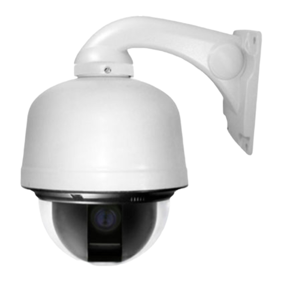
- Page 1 HIGH SPEED DOME CAMERA User Manual 650 TVL DSC-737SE...
-
Page 3: Table Of Contents
Table of contents Ⅰ CAUTION --------- Ⅱ INTRODUCTION OF PRODUCTS --------- DIRECTIONS FOR USE Ⅲ --------- 14 FUNCTIONAL SETTING BY THE KEYBOARD Ⅳ --------- 27 OSD MESSAGE DISCRIPTION Ⅴ --------- 30 TROUBLE SHOOTING Ⅵ --------- 32 DIMENSION Ⅶ --------- 34 ASSEMBLY Ⅷ... -
Page 4: Ⅰ Caution
Ⅰ. CAUTION Thank you for purchasing our product. Please operate the product after being fully aware of the manual. Pease contact us if you have any queries. Precaution Note the following matters before the installation of the product. Avoid the following places for the installation. A high/low temperature: Using indoor-cameras Snow, rain and wet: Humidity or water and in the places of +50°C~ -10°C can cause... -
Page 5: Caution In Use
Caution in Use Do not disassemble the unit and put alien substances in the unit. Disassembling the unit or putting alien substances such as a metal can make the camera defective. - Make sure of power switch-off before the installation. : Ensure power switch-off and check the voltage the camera before the installation. -
Page 6: Ⅱ Introduction Of Products
Ⅱ. INTRODUCTION OF PRODUCT 1. DESCRIPTION AND FEATURES Description This camera has been designed elegantly for buildings, department stores that need to be in harmony with the interior as a high speed dome camera, including various observation functions. Features ☺ High Resolution and Zoom Rate High resolution 650 TVL with Sony 960H CCD and Built-in High Zoom (28X, 37X) Rate Camera with 12x Digital Zoom ☺... -
Page 7: Installation And Connection
2. INSTALLATION AND CONNECTION 1) Name and function of each part Indoor Type Outdoor Type (UPPER COVER) The camera’s body goes to here and a power cable, data cable, video cable, sensor have been connected with this (DOME DRIVER) A main body that has a built-in the control units and camera (LOWER COVER) - Page 8 2) Installation Indoor Type Outdoor Type SEPARATION OF LOWER COVER (Indoor type) Loosen the bolt of the back lower cover screwdriver(+), then turn the cover as above the picture and pull the lower cover to the down (Outdoor type) Loosen the four bolts of the lower cover, then separate.
- Page 9 Open the connector cover, then connect power, data, video cable and sensor The cover is opened if user loosens the one bolt on the connector cover by using a screwdriver(+). The bolts not loosened completely to protect from missing of them. Be careful that each cable which each function is changed wrong Have you connect the power cable...
- Page 10 3) How to connect equipments DC12V/1A adaptor and junction box are provided on a purchase, Junction box consists of 2 data ports ( Each data port can be connected with maximum up to 128 cameras and sub keyboard terminal Connect the image line of a monitor Reference to the following page.
- Page 11 Alarm output is tangency output of relay non-load, it can be used up to AC220/10A by connecting the load. The switch is automatically turned on when the sensor works and it is possible to cancel by using the controller after a limited The sensor time Can be connected maximum 4 channels and the camera...
- Page 12 PROTOCOL SW 2 SW 1 SW 3 SW 7 SW 8 SW ‘INIT ADDR’ D-MAX (9600 INIT bps) P-P (9600 bps) INIT P-P (4800 bps) INIT P-P (2400 bps) INIT P-D (9600 bps)
- Page 13 5) SETTING ADDRESS OF DIP SWITCHES DIP SWITCH (HEX) DIP SWITCH (HEX) -No.1 is changed to No.64 and the last No.64 is changed No.128 when No.7 DIP SW is on. -No.1 is changed to No.129 when No.7 DIP SW is off and No.8 DIP SW is on. -No.1 is changed to No.193 and user can set up to maximum 255 ADDRESS when No.7, 8 DIP SW are on.
-
Page 14: Ⅲ Directions For Use
Ⅲ. DIRECTIONS FOR USE ● OSD (ON SCREEN DISPLAY) menu control It is the function to call up the Menu *User can not only set Preset, Group, Tour, Swing, Trace functions of the camera up by the menu, but also set them up by shortening keys. - Page 15 1. ID SET. ◄◄ CAMERA SETUP p1 ►► 1. ID Set : Press F/F Key 2. OSD Display. : ID + Status 3. H-V Reverse. : Normal 4. AGC Control : 05 5. Shutter speed. : AUTO 6. Sharpness level : 20 7.
- Page 16 5. SHUTTER SPEED ◄◄ CAMERA SETUP p1 ►► As a setting shutter speed mode, it can be distinguished a fast 1. ID Set : Press F/F Key 2. OSD Display. : ID + Status moving subject easily by means of shutter speed up. 3.
- Page 17 9. Slow AE ◄◄ CAMERA SETUP p1 ►► When the scene brightness is changed, camera exposure is 1. ID Set : Press F/F Key 2. OSD Display. : ID + Status adjusted to new condition. Normally the AE is set to work at fast 3.
- Page 18 HSBLC MODE ▶ - HSBLE LEVEL: Adjust the HLC Sensitivity by selecting Low, Medium or ◄HSBLC SETUP PAGE ► High - HSBLC LEVEL : 2(0~5) -MASK STATE : ON - MASK STATE: when user select “On” mode, mask areas will be appear -MASK COLOR :GRAY on the monitor.
- Page 20 - IR Correction You can enable or disable the IR (Infra-Red) correction to support IR light or not. Zoom and focus trace data will be switched according to IR correction ON/OFF. We will only support 850nm IR light source. The IR correction can be enabled on night (IR-pass) filter. ◄◄...
- Page 21 ② Preset PTZ set : Set the position of Preset Select the main menu with the joystick, then press F/F key for next page. Select [SAVE] with F/N key after setting the Preset point by using the joystick and. In/Out •[SAVE]: Previous screen.
- Page 22 ④ GROUP SET: User can set maximum 12 groups. Select a channel then move to next page after pressing F/F key ※The Preset point in the Group that 12 Preset points are set is observed repeatedly and order with regular speed and time. ⑤...
- Page 23 20. TRACE SET PAGE ◄◄ CAMERA SETUP p3 ►► Set TRACE. 18.STABILIZ On/Off : Off User can regenerate and save a change of the unrestricted 19. Preset Set & Run Page 20.Trace Set Page location of ZOOM In/Out and a position of the camera by hand- 21.
- Page 24 - Resume Time Set : It can select the delay time that the camera move to the place alarming to observe where wrong signal is sensed. User can set it for 1sec to 180sec and operate GROUP, TOUR, SWING again in a preset time. SWING, GROUP, TOUR are operated in a preset time when user stops the operating joystick in the case of...
- Page 25 ◄◄ PRIVACY ZONE SETUP ►► -CH01: Blank -CH02: Blank -CH03: Blank -CH04: Blank -CH05: Blank -CH06: Blank -CH07: Blank -CH08: Blank -ZONE COLOR :BLACK - Press F/F button to enter SET mode. -TRANSPARENCY - PREV MENU PAGE F/F Select, L/R Change █...
- Page 26 26. MANUAL P/T SPEED ◄◄ CAMERA SETUP p4►► User can control the maximum speed in controlling of up and down. 24. Auto Tilt Mode : Off It can be set Low, Medium, Max and one turn (360°/sec) is possible 25.Smart Pan/tilt : ON 26.
- Page 27 29. USE PASSWORD ◄◄ CAMERA SETUP p4►► input the password 24. Auto Tilt Mode : Off 25.Smart Pan/tilt : ON available set On/Off mode; off mode is factory set 26. Manual P/T Speed : Medium press the F/F button as On mode 27.Auto Refresh Time :1day 28.
-
Page 28: Ⅳ Functional Setting By The Keyboard
Ⅳ. Functional Setting by the Keyboard 1. Preset setting You can set Preset point up to 250. Preset Input. ① Preset setting can be set 1 to 250 sequentially after moves the camera to where you want ② Preset Move The camera moves to the preset point, if you press Preset No. - Page 29 ② Operation of Swing ③ End of Swing (Run Pan) (Run Tilt) 3. Group setting ① Start Group setting mode Start the Group Select the Group in 1~12 Select in Preset No.1~250 setting mode and input them. Move Speed: Dwell Time: The Speed from A to B The dwell time at the point of 64=High, 1=Low...
- Page 30 ■ Repeat input in continual input EX). Register Group No. 1, 3, 6 as Tour Register Register Finish Start Register Tour No.2 Tour mode Tour No.1 Tour No.3 Tour mode ② Start / End Tour ③ Delete Tour Start Tour Finish Tour 5.
-
Page 31: Ⅴ Osd Message Discription
Ⅴ. OSD MESSAGE DISCRIPTION 1. PRESET MESSAGE CAM-001 CAM-001 CAM-001 SET PST 001 PRESET 001 CLEAR PST 001 User check that displayed when It is displayed when user preset No.1 is saved as an moving to the preset No.1 deletes preset No.1. the “... - Page 32 CAM-001 CAM-001 CAM-001 SET TOUR GP:01 TOUR&GP:01 PRESET:001 CLEAR TOUR & GRP As the message in the time It shows the data in group As the message in the of operation of Tour set, and tour saved was deleted. time of operation of tour “GP:01”...
-
Page 33: Ⅵ Trouble Shooting
Ⅵ. TROUBLE SHOOTING 1. You must turn off the power switch before installation of this equipment 2. Avoid installation places where it is the ultimate cold, hot, and humid. 3. Use a power supply of AC24V, 1.5A output. 4. Please be careful that you connect respective wires without mismatching in installation. 5. - Page 34 When it occurred alarm state, it is not Did you set the preset in the set Check setting status of the alarm exactly presser position or different. mode? preset in the set mode. When it activate alarm state, there is Did you use the exclusive control It is need to use an exclusive control no sign on the keyboard controller...
-
Page 35: Ⅶ Dimension
Ⅶ. DIMENSIONS Wall mount bracket Outdoor Type Indoor Type... - Page 36 Ceiling mount bracket Indoor Type Outdoor Type In-ceiling mount bracket...
-
Page 37: Ⅷ Assembly
Ⅷ. ASSEMBLY DSC-30EWP Wall mount bracket Remove ① main body camera from the housing ③ Fix the upper cover into a wall bracket with turning it in the same direction as the picture ④ Connect the data cable, video cable and power source cable. ②... - Page 38 DSC-20ECP Wall mount bracket Assembly of outdoor dome with pole mount pendant Remove Main body of The camera Turn the ceiling From the Housing. pole to connect. Fix the pole ceiling. Turn the joint coupler connect. Turn the cover coupler connect.
- Page 39 Main & Sub Keyboard configuration...
-
Page 40: Ⅸ Specification
Ⅸ. SPECIFICATIONS □ □ MODEL 28X Zoom 37X Zoom Image sensor 1/4” Sony double scan CCD∥ Total / Effective pixels NTSC: 520K / 480K PAL: 610K / 570K Horizontal resolution Color : 650 TVL, B/W 750 TVL 28x Optical zoom, f =3.5 ~98mm 37x Optical Zoom f =3.5 ~ 129.5 mm Lens (Digital Zoom) F 1.5(Wide End), F 3.7(Tele End) - Page 44 DISTRIBUTED BY...
Need help?
Do you have a question about the DSC-737SE and is the answer not in the manual?
Questions and answers