Table of Contents
Advertisement
Advertisement
Table of Contents

Subscribe to Our Youtube Channel
Related Manuals for D-MAX DSC-2000Si


Summary of Contents for D-MAX DSC-2000Si
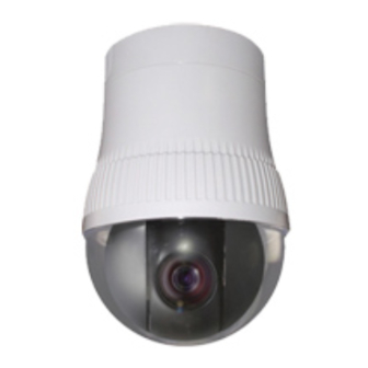
- Page 1 HIGH SPEED DOME CAMERA USER MANUAL DSC-2000Si/Se...
-
Page 3: Table Of Contents
Table of contents CAUTION -------------------------------------------------------------------------------- INTRODUCTION OF PRODUCT 1). DESCRIPTION AND FEATURES --------------------------------------------- 2). INSTALLATION AND CONNECTION ---------------------------------------- 2-1. NAME AND FUNCTION OF EACH PART ----------------------------- 2-2. INSTALLATION -------------------------------------------------------------- 2-3. BASIC CONNECTION ----------------------------------------------------- 2-4. CONNECTION DIAGRAM ------------------------------------------------ DIRECTIONS FOR USE 1). -
Page 4: Caution
1.CAUTION Thank you for purchasing our product. Please operate the product after being fully aware of the manual. Pease contact us if you have any queries. Precaution Note the following matters before the installation of the product. Avoid the following places for the installation. A high/low temperature: Using indoor-cameras Snow, rain and wet: Humidity or water and in the places of +50°C~ -10°C can cause... -
Page 5: Caution In Use
Caution in Use Do not disassemble the unit and put alien substances in the unit. Disassembling the unit or putting alien substances such as a metal can make the camera defective. - Make sure of power switch-off before the installation. : Ensure power switch-off and check the voltage the camera before the installation. -
Page 6: Introduction Of Product
2. INTRODUCTION OF PRODUCT 1) DESCRIPTION AND FEATURES This camera has been designed elegantly for buildings, department stores that need to be in harmony with the interior as a high speed dome camera, including various observation functions. ☺ 30x Zoom lens ☺... -
Page 7: Installation And Connection
2) INSTALLATION AND CONNECTION 2-1. Name and function of each part INDOOR TYPE OUTDOOR TYPE Connect it with cover housing or bottom cover, then combine with bracket. It protects inside the camera, and built-in pan It is a part to be makes the heat connected with power, cool when using... -
Page 8: Installation
2-2. Installation INDOOR TYPE OUTOOR TYPE Open the cover with unscrewing 5 bolts, then separate the camera body from the cover Unlock the device of the bottom cover, then housing with turning it as the same direction in separate the camera body cover from the the picture bottom cover with turning it as the same (the bolt of the bubble cover is not separated... - Page 9 LOCK DEVICE : Check the direction when it connects with camera body case, And lock it with DSC-1000Si AC24V INPUT Use AC24V power and use either terminal power connect or jack POWER LED : power connect. Power LED is turned when the power is ON DATA IN ( RS-485) : Never connect the power into...
-
Page 10: Basic Connection
2-3. Basic Connection DC12V 1A adaptor and junction box are provided on a purchase. Junction box consists of 2 data ports (each data port can be connected with maximum up to Connect the video line of a 128 cameras and sub keyboard terminal. monitor User can control maximum up to 255 cameras... -
Page 11: Connection Diagram
2-4. Connection diagram Must use AC24V power source. The current value must be 1.5A or more and use a double winding transformer. Alarm output is tangency output of relay non-load. It can be used up to AC 220V/10A by connecting with the load. The switch is automatically turned on when the sensor works and it is possible to cancel by using the... -
Page 12: Directions For Use
3. DIRECIONS FOR USE 1). DIP SWITCH SETTING Set the camera numbers in the state of ADDR, set communication speed, protocol in the state of INIT. This part is each address of camera. -Termination Resistor (DIP SW NO1) -Address /Initial select (DIP SW NO3) -Turn the last camera on the data line as a switch -Set the DIP SW up in the ADDRESS. -
Page 13: How To Change Protocol
2) HOW TO SET PROTOCOL Set this part up Do not necessary to set it up The switch to select protocol The switch to select baud rate Change No.3 at S2 to INIT if user wants to change Protocol. ① Please the power off. ②... -
Page 14: Setting Address Of Dip Switches
3) SETTING ADDRESS OF DIP SWITCHES Use DIP switches No.1 to No.8 for address, it can be set 1 program to 255 program. DIP SWITCH (HEX) DIP SWITCH (HEX) -No.1 is changed to No.64 and the last No.64 is changed No.128 when No.7 DIP SW is on. -No.1 is changed to No.129 when No.7 DIP SW is off and No.8 DIP SW is on. -
Page 15: How To Use Osd Menu
4) HOW TO USE OSD MENU 4-1. How to control OSD menu ● OSD (ON SCREEN DISPLAY) CONTROL It is the function to call up the Menu *User can not only set Preset, Group, Tour, Swing, Trace functions of the camera up by the menu, but also set them up by shortening keys. -
Page 16: Functional Descriptions On Each Menu
4-2. Functional Descriptions of each Menu. 1. ID SET. It is the function to set ID of the camera. Move to No.1 menu and the screen moves as following when user presses F/F key. User can choose letters that they want, if user control a joystick up / down / right / left, and user can reselect the previous letters, if user presses Z/I, Z/O or turn the head of the joystick to right/left. - Page 17 4. AGC LEVEL AGC(Automatic Gain Control)- It adjusts the amount of video amplification to maintain a full 1-volt peak-to-peak video signal output automatically. ▶ Range : Auto, 8Db, 10Db, ----- 38dB 5. SHUTTER SPEED As a setting shutter speed mode, it can be distinguished a fast moving subject easily by means of shutter speed up.
- Page 18 8. FLICKERLESS Tremble on the screen is removed in the state of FLICKERLESS ‘ON’, the shutter speed, at the same time, is fixed in 1/120sec in NTSC and in 1/100sec in PAL. ※Move the joystick down then choose “NEXT MENU PAGE” on the screen to move next page.
- Page 19 11. FOCUS MODE Change Focus Mode to hand-worked or auto. ▶ OneShot : Auto Focusing mode works during non-working after zoom is worked. ▶ Auto : It adjusts the focus automatically as it monitors the screen. ▶ Manual : User can control the focus by hand-worked. 12.
- Page 20 15. STABILIZ On/Off There is some tremble as zoom magnification is high, the function can compensate the tremble. ▶ On / Off 16. Motion Detection Set Motion ‘On’ after move the camera where user wants. It displays the message ‘Motion Detected’ on the screen when the moving of an object is sensed on the same screen.
- Page 21 ② Preset PTZ set : Set the position of Preset. Select the main menu with the joystick, then press F/F key for next page. Select [SAVE] with F/N key •[SAVE]: Previous screen. [DELETE]: Remove. [ESC]: Cancel after setting the Preset point by using the joystick and.
- Page 22 ④ GROUP SET: User can set maximum 12 groups. Select a channel then move to next page after pressing F/F key ※The Preset point in the Group that 12 Preset points are set is observed repeatedly and order with regular speed and time. ⑤...
- Page 23 Selection of this menu. 18. TRACE SET PAGE Set TRACE. User can regenerate and save a change of the unrestricted location of ZOOM In/Out and a position of the camera by hand-worked control with a joystick. User can see the screen when moves the joystick to Right/Left after fixing the cursor on the menu ■...
- Page 24 - Resume Time Set : It can select the delay time that the camera move to the place alarming to observe where wrong signal is sensed. User can set it for 1sec to 180sec and operate GROUP, TOUR, SWING again in a preset time. SWING, GROUP, TOUR are operated in a preset time when user stops the operating joystick in the case of not connecting with the ALARM.
- Page 25 ④ Fix the black square on the middle of area that you want to hide by a joystick, then go back to the previous page by [F/F] key after controlling the size of the square by [Z/I], [Z/O] key and saving it. Set the position BOX Extension / Reduction Check ⑤...
- Page 26 22. AUTO TILT MOVE The PAN is turned in a 180° degree arc automatically when the angle of the camera moves down to the maximum degree, therefore, it is possible to track objects continuously. 23. SMART PANTILT It is a function that P/T speed is getting slower as Zoom in. It is hard to observe objects with the high PANTILT speed in operating of Zoon In This function makes the speed less automatically for the...
- Page 27 26. FACTORY RESET WARNING Please be careful of that all setting data of OSD MENU are reset into the first default when operates FACTORY RESET WARNING. The setting data of Preset, Swing, Group, Tour, Trace, also is deleted all.
-
Page 28: Functional Setting, Operation/Deletion The
4-3. Functional Setting, Operating/Deletion by the Keyboard 1. Preset setting You can set Preset point up to 250. ① Preset Input. Preset setting can be set 1 to 250 sequentially after moves the camera to where you want ② Preset Move The camera moves to the preset point, if you press Preset No. - Page 29 ② Operation of Swing ③ End of Swing (Run Pan) (Run Tilt) 3. Group setting ① Start Group setting mode Start the Group Select the Group in 1~12 Select in Preset No.1~250 setting mode and input them. Move Speed: Dwell Time: The Speed from A to B The dwell time at the point of 64=High, 1=Low...
- Page 30 ■ Repeat input in continual input EX). Register Group No. 1,3,6 as Tour Register Start Register Register Finish Tour No.2 Tour No.3 Tour mode Tour mode Tour No.1 ② Start / End Tour ③ Delete Tour Start Tour Finish Tour 5.
-
Page 31: Osd Message Description
4-4. OSD MESSAGE DISCRIPTION... -
Page 33: Trouble Shooting
4. TROUBLE SHOOTING... -
Page 34: Dimension
5. DIMENSION Wall mount bracket Ceiling mount bracket... - Page 35 In-ceiling mount bracket...
-
Page 36: Assembly
6. ASSEMBLY DSC-30EWP Wall mount bracket ②Connect each cables, then screw 4 bolts. Block up beside the hole with 34mm BLANK RUBBER ③In set of it on the concrete, connect the cables as above the picture and join TAB/P1/11” flexible connector(28Ø) Unscrew the 5bolts from the Bubble cover ①... - Page 37 ⑤Connect the Data, Video, Power cables. ⑦Connect the Bubble again. (Refer to page 7) Connect the Hous ing with the camera body. ⑥ Please check the triangular mark on the side of the body and inside.
- Page 38 DSC-20ECP Wall mount bracket ②Fix the Pole box from the ceiling. Unscrew the 5bolts from the Bubble cover ① and open it, then separate the Camera body from the Cover housing. (The bolts from the Bubble cover are not separated completely.) ⑤Turn the Cover housing tight.
- Page 39 Connect the Data, Video, Power ⑥ cables. (Reference to Installation and Connection.) ⑦Connect the Housing with the camera body. Please check the triangular mark on the side of the body and inside. ⑧Connect the Bubble again. Ceiling bracket is used as In/Outdoor type and you can remove or extend the Ceiling pole to fix the length.
- Page 41 Ceiling Adhesion bracket...
- Page 42 Set sub keyboard...
- Page 43 Set one main keyboard...
-
Page 44: Specification
6. SPECIFICATION MODEL DSC-2000Si (Indoor ) Signal system NTSC Image sensor 1/4” Sony HAD CCD Effective pixels 768(H) X 494(V), 752(H) X 582(V), Horizontal resolution More than 520 TVL, B/W 570 TVL Lens 30x Optical zoom, f =3.3 –99mm Digital zoom... - Page 45 MODEL DSC-2000Se ( Outdoor ) Signal system NTSC Image sensor 1/4” Sony HAD CCD Effective pixels 768(H) X 494(V), 752(H) X 582(V), Horizontal resolution More than 520 TVL, B/W 570 TVL Lens 30x Optical zoom, f =3.3 –99mm Digital zoom 10x (Total zoom 300x) Angle of view Approx 58.17°...
- Page 48 DISTRIBUTED BY...
Need help?
Do you have a question about the DSC-2000Si and is the answer not in the manual?
Questions and answers