Advertisement
Advertisement

Subscribe to Our Youtube Channel
Related Manuals for D-MAX DCC-500F


Summary of Contents for D-MAX DCC-500F
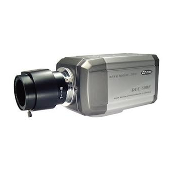
- Page 1 Digital Day & Night COLOR CAMERA USER MANUAL...
- Page 2 CAUTION RISK OF ELECTRIC SHOCK DO NOT OPEN CAUTION : TO REDUCE THE RISK OF ELECTRIC SHOCK, DO NOT REMOVE COVER(OR BACK), NO USER SERVICEABLE PARTS INSIDE. REFER WERVICING TO QUALIFIED SERVICE PERSONNEL. The lightning flash with an arrowhead symbol, within an equilateral triangle is intended to alert the user to the presence of uninsulated dangerous voltage within the product's enclosure that may be of sufficient magnitude to...
-
Page 3: Table Of Contents
Warning Contents The camera needs periodic inspection. 1. Features Contact an authorized technician for inspection. 2. Components & Cable Connection Stop using your camera when you find a malfunction. If you use your camera around smoke or 3. Names and functions of parts unusual heat for a long time, fire may be caused. -
Page 4: Features
1. Features High Sensitivity The built-in high sensitivity SONY COLOR CCD Horizontal Resolution 530 TVLines enables a clear image even in 0.3Lux(0.1Lux Clear image quality has been achieved by B/W) or as low as 0.002Lux with SENS-UP. employing a SONY CCD with 410,000 (effective) pixels, which provides a horizontal resolution of 530 TV lines. -
Page 5: Names And Functions Of Parts
2. Components 3. Names and Functions of Parts 1) COLOR CAMERA 2) AUTO IRIS LENS CONNECTION PLUG 1) Front Lens protection cap Please cover the lens when not using it. CS-Mount lens adaptor Please attach the CS-Mount lens here. 3) C-MOUNT ADAPTOR Back Focus clamp screw Please loosen the clamp screw with a screwdriver before adjusting the Back Focal... - Page 6 The mounting bracket can be separated and Power lamp attached to the top of the camera. Lights up when the correct power is supplied to In this instance please do not tighten the screw the camera. to a depth of more than 5mm, otherwise Setting button serious damage can occur to the inside of the SETUP button : Used for the menu display.
- Page 7 4. Installation 1) Lens Lenses are sold separately. Lenses such as auto iris lens, CS-Mount lens and C-Mount lens can be - Please remove the cover of the auto iris lens used. connection plug and solder the lens cable to the connector pin in the plug.
- Page 8 then attach the auto iris lens to the camera by When using a CS-Mount lens screwing it in clockwise. Please take off the lens protection cap and attach - Please insert the connection plug that is the CS-Mount lens to the camera by screwing it in connected to the auto iris lens cable into the clockwise.
- Page 9 the type of monitor and accessories. Note Please use the specified lens connection parts as Please refer to the user's manual for each instrument. shown in the picture below. Please turn off the power when connecting. The use of the wrong sized parts may cause damage to the inside of the camera or result in 3) Connecting to power poor fitting.
-
Page 10: Setup Menu Operation
5. Setup Menu Operation SETUP Select any function Modes can be LENS MNUAL you wish to operate SHUTTER changed using the 1) Settings WHITE BAL by using the UP LEFT and RIGHT BACKLIGHT and DOWN buttons. buttons. SENS-UP SPECIAL EXIT Please press the LEFT or RIGHT button if you wish to change mode. - Page 11 3) SHUTTER SETUP When the SETUP menu LENS is displayed on the Auto or manual control can be selected. SHUTTER WHITE BAL screen, please position BACKLIGHT SETUP When the SETUP menu the arrow to point to LENS MNUAL is on the screen, please SHUTTER SENS-UP 'LENS' by using the UP...
- Page 12 Please select 'MANUAL' mode if you wish to Please position the arrow to point to 'WHITE adjust the shutter manually. BAL' on the SETUP menu by using the UP and - You can select speed from '1/60' to DOWN buttons '1/120,000'sec (NTSC Models), '1/50' to Please select the mode you wish to operate by '1/120,000'sec (PAL Models).
- Page 13 Note Please select the mode you wish to operate by pressing the LEFT or RIGHT button. Under the following conditions the WHITE BALANCE function may not operate properly. - HIGH : The gain increases from 0dB up to 42dB. In such cases, please select the AWC mode. - MIDDLE : The gain increases from 0dB up to When the object's surroundings have a very 30dB.
- Page 14 As the level of gain increases, the screen gets - MIDDLE : The most effective mode. There is a brighter and the level of noise also increases. sufficient reduction in noise levels without - HIGH : The gain increases or decreases within causing much ghost imaging.
-
Page 15: Special Menu Operation
6. Special Menu Operation by pressing the SETUP button in 'AUTO' mode.(X2~X128) As the magnification increases, the screen gets 1) SPECIAL MENU brighter; however the after image also Please position the SETUP increases LENS MNUAL arrow to point to SHUTTER If storage magnification is increased while WHITE BAL 'SPECIAL' on the... - Page 16 Note Camera ID A B C D E F G H I J K L M If the wrong name has been input..NOPQRSTUVWXYZ a b c d e f g h i j k l m If you press the SETUP button after moving the n o p q r s t u v w x y z - .
- Page 17 ON : The color mode SPECIAL CAMERA ID is selected by default, COLOR and the modes do not SYNC MOTION DET change Automatically. PRIVACY MIRROR SHARPNESS RESET RETURN Please find the position you wish to display the Note name by using the 4 directional buttons, and When the AGC is turned off, COLOR does not then press the SETUP button.
- Page 18 individual can conduct supervision efficiently. Please press the SETUP button to save the The camera detects an object's movement by changes and complete the setting. sensing disparity of outline, and level of brightness and color. 6) PRIVACY Please press the SETUP button. This mode conceals the areas you do not wish to - OFF : MOTION DETECTION mode is appear on the screen.
- Page 19 The outline of the video image becomes cleaner Please adjust the size of the area to be concealed by using the UP, DOWN, LEFT Or and more distinctive as the level of SHARPNESS increases. If the level goes up excessively, RIGHT button.
-
Page 20: Troubleshooting
7. Troubleshooting Problems Troubleshooting The MOTION Please check if an appropriate power If there are problems in operation, please refer to the DETECTION source to the camera complies with the items below. If the problem persists, please contact function is not manufacturer's standard requirement, or working. -
Page 21: Specifications
8. Specifications SIGNAL SYSTEM NTSC TOTAL / EFFECTIVE PIXEL 410K / 380K Pixels 470K / 440K Pixels IMAGE SENSOR 1/3" SONY interline transfer CCD HORIZONTAL RESOLUTION 530 TV Line MINIMUM ILLUMINATION 0.3 Lux / F 1.2, 0.01Lux with Sensitive Up DAY &... - Page 22 DISTRIBUTED BY...
Need help?
Do you have a question about the DCC-500F and is the answer not in the manual?
Questions and answers