Jøtul GF 400 BV Sebago Installation And Operation Instructions Manual
Hide thumbs
Also See for GF 400 BV Sebago:
- Installation and operation instructions manual (28 pages) ,
- Installation and operation instructions manual (28 pages)
Table of Contents
Advertisement
Installation
and
Operation
Instructions
WARNING:
IF THE INFORMATION IN THESE INSTRUCTIONS
ARE NOT FOLLOWED EXACTLY, A FIRE OR EXPLO-
SION MAY RESULT CAUSING PROPERTY DAMAGE,
PERSONAL INJURY OR LOSS OF LIFE.
FOR YOUR SAFETY:
DO NOT STORE OR USE GASOLINE OR OTHER
FLAMMABLE VAPORS AND LIQUIDS IN THE VICIN-
ITY OF THIS OR ANY OTHER APPLIANCE.
INSTALLATION:
INSTALLATION AND SERVICE MUST BE PER-
FORMED BY A QUALIFIED INSTALLER, SERVICE
AGENCY OR LICENSED GAS SUPPLIER.
THIS PRODUCT MUST BE INSTALLED BY A
LICENSED PLUMBER OR GAS-FITTER WHEN
INSTALLED IN THE COMMONWEALTH OF
MASSACHUSETTS.
A CARBON MONOXIDE (CO) DETECTOR SHALL
BE INSTALLED IN THE SAME ROOM AS THE
APPLIANCE.
WHAT TO DO IF YOU SMELL GAS:
• DO NOT TRY TO LIGHT ANY APPLIANCE.
• DO NOT TOUCH ANY ELECTRICAL SWITCHES.
• DO NOT USE THE PHONE IN YOUR BUILDING.
IMMEDIATELY CALL YOUR GAS SUPPLIER FROM A
NEIGHBOR'S PHONE.
• FOLLOW YOUR GAS SUPPLIER'S INSTRUCTIONS.
• IF YOU CANNOT REACH YOUR GAS SUPPLIER,
CALL THE FIRE DEPARTMENT.
AVERTISSEMENT:
ASSUREZ-VOUS DE BIEN SUIVRE LES INSTRUC-
TIONS DANS CETTE NOTICE POUR REDUIRE AU
MINIMUM LE RISQUE D'INCENDIE OU POUR EVITER
TOUT DOMMAGE MATERIEL, TOUTE BLESSURE OU
MORTALIT'E.
NE PAS ENTREPOSER NI UTILISER D'ESSENCE NI
OU LIQUIDES INFLAMMABLES DANS LE VOISINAGE
DE CET APPAREIL OU DE TOUT AUTRE APPAREIL.
L'INSTALLATION LE SERVICE DOIVENT ETRE
EXECUTES PAR UN INSTALLATEUR QUALIFIE,
AGENCE DE SERVICE OU LE FOURNISSEUR DE
GAZ.
QUE FAIRE SI VOUS SENTEZ UNE ODEUR DE GAZ.
• NE PAS TENTER D'ALLUMER L'APPAREIL
• NE TOUCHEZ A AUCUM NTERRUPTEUR.
• NE PAS VOUS SERVIR DES TELEPHONES SE
TROUVANT DANS LE BATIMENT OU VOUS VOUS
TROUVEZ.
• APPELEZ IMMEDIATEMENT VOTRE FOURNISSEUR
DE GAZ CHEZ UN VOISIN. SUIVEZ LES INSTRUC-
TIONS DU FOURNISSEUR.
• SI VOUS NE POUVEZ REJOINDRE LE
FOURNISSEUR DE GAZ, APPELEZ LE SERVICE DES
INCENDIES.
1
Advertisement
Table of Contents

Subscribe to Our Youtube Channel
Related Manuals for Jøtul GF 400 BV Sebago


Summary of Contents for Jøtul GF 400 BV Sebago
- Page 1 WARNING: IF THE INFORMATION IN THESE INSTRUCTIONS ARE NOT FOLLOWED EXACTLY, A FIRE OR EXPLO- SION MAY RESULT CAUSING PROPERTY DAMAGE, PERSONAL INJURY OR LOSS OF LIFE. FOR YOUR SAFETY: DO NOT STORE OR USE GASOLINE OR OTHER FLAMMABLE VAPORS AND LIQUIDS IN THE VICIN- ITY OF THIS OR ANY OTHER APPLIANCE.
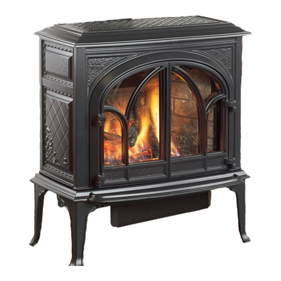
- Page 2 We’ve been building fine quality cast iron stoves and fireplaces continuously since 1853. The Jøtul GF 400 BV Sebago combines advanced gas technology with the warm, traditional elements of cast iron. With proper care and use, your stove will provide you with many years of safe, dependable and satisfying service.
-
Page 3: Table Of Contents
Table of Contents Jøtul GF 400 BV Service Tools ..........4 Sebago Specifications ........... 4 Gas Heater General Information ....... 5 Safety Information ........6 Manufactured and Distributed by: Installation Requirements Jøtul A.S.A. Location ..........6 Fredrikstad, Norway Hearth Protection ......6 Jøtul North America Clearances .......... -
Page 4: Service Tools
GF 400 BV Sebago Specifications The Jøtul GF400 BV Sebago is a atmospherically- vented gas fireplace heater designed only for THIS FIREPLACE IS SHIPPED FROM THE FACTORY vertical venting directly to the outside of the house, FOR USE WITH NATURAL GAS ONLY. FOR USE WITH using listed, Type B-vent pipe. -
Page 5: General Information
Consult the local or national installation code(s) to General Information assure that adequate combustion and ventilation air is available. Installer l’appareil selon les codes ou reglements THIS HEATER MUST BE INSTALLED AND MAINTAINED locaux, ou, en l’absence de tels reglements, selon les BY A QUALIFIED SERVICE AGENCY. -
Page 6: Safety Information
Safety Information Location During normal operation, the GF 400 BV gas stove will In selecting a location for the stove, consider the reach high surface temperatures. Therefore: following points: 1) Heat distribution 2) Vent termination requirements Due to the high operating temperatures, this appli- 3) Gas supply line routing ance should be located out of traffic areas and away 4) Traffic areas, furniture, draperies, etc. -
Page 7: Clearances
Stove and Vent Clearance Requirements Minimum Clearances from the Stove to Combustibles See figs. 2-3. 3” (51 mm) Rear: 3” (76 mm) - measured from Draft Hood To Rear Wall Ceiling: 32 1/4” (819 mm) - measured from stove top Corner: 3”... - Page 8 Vent Requirements The GF 400 BV Sebago is specifically designed to operate using 4” Type B vent pipe components or a Listed Flexible gas liner. • All venting components must be installed in accor- dance with the terms of their listing and manufacturer’s instructions.
- Page 9 Venting through a Masonry or Prefabricated Manufactured Chimney • When 6” diameter decorative pipe is installed to cover the venting any Listed Flexible Gas liner must be connected directly to the stove’s draft hood. Listed Storm collar termination required • Use of single wall connector pipe as a vent is cap required Top sealing prohibited for use with the GF400 Sebago B-Vent...
-
Page 10: Vent Requirements
Approved B-Vent Configurations Listed B-Vent Listed B-Vent Termination Cap Termination required. Cap required. Maximum total Maximum NOTE: horizontal chimney Installation at anywhere in height off altitude greater NOTE: venting Draft Hood is than 2000’ Installation at configuration 35 feet. requires altitude greater is 4 feet. -
Page 11: Fuel Conversion
Conversion Kit Contents: Fuel Conversion • 1, regulator tower labeled for propane • 3, regulator tower screws • 1, burner orifice (3.20 mm for NG, #49 for LPG) The GF 400 BV gas stove is shipped from the factory • 1, pilot orifice (#51 for NG, #30 for LPG) equipped to burn NATURAL GAS only. - Page 12 7. Lift out the Burner Plate: NOTE: There are no screws securing the Burner to the floor of the firebox. Pull the Air Shutter forward and lift the burner together with shutter up and out of the stove as a unit. See fig. 13. Air Shutter 8.
-
Page 13: Gas Connection
Regulator Tower Pilot Head Remove black gasket Orifice from regulator assembly Retainer Clip Valve Pilot Base Figure 16. Pilot orifice removal and replacement. Figure 17 Regulator assembly. 15. Install the new regulator: Be sure the new gasket is Gas Supply Connection properly positioned and tighten screws securely. -
Page 14: Gas Pressure
Figure 19. Pressure test points. INLET GAS PRESSURES (inches water column) Figure 18. Supply valve connection fittings. NATURAL GAS PROPANE 12.0 14.9 Leak test: The appliance and its appliance main gas valve 1. Mix a 50-50 solution of water and dish must be disconnected from the gas supply piping soap. -
Page 15: Log Set Installation
Log Set Installation Brick Kit Note: Install the optional Antique Brick Kit 155370 before installing the logset. See page 22 and PN 220646 the instructions provided with that kit. The GF 400 BV logset must be installed before operating the burner. The logset includes six log pieces, and a bag of ember stones packaged inside the firebox. -
Page 16: Flame Adjustment
Flame Appearance / Air Shutter Optional Wall Thermostat or Adjustment Remote Control The GF 400 BV gas stove is shipped from the factory Use only a 750 millivolt DC two-wire circuit thermostat equipped to burn Natural gas. If the stove has been with this appliance. -
Page 17: Decorative Pipe
The use of decorative pipe is optional. No decorative ance for the first time, it will take a few moments to pipe is included with the Jøtul GF 400 BV Sebago, clear the gas line of air. Once this purge is complete,... -
Page 18: Operation
If a vacuum is used during any service on the stove, WARNING: ALWAYS be sure the stove is cold and there are NO hot AIR SHUTTER ADJUSTMENTS SHOULD ONLY BE embers. PERFORMED BY A QUALIFIED PROFESSIONAL 5. Remember, this appliance has a continuous burning SERVICE TECHNICIAN. -
Page 19: Maintenance
Maintenance FOR REPLACEMENT, USE ONLY JØTUL CERAMIC GLASS REPLACEMENT KIT Your Jøtul GF 400 BV Sebago and its venting system 155599. DO NOT USE ANY OTHER TYPE OF should be inspected before use and at least annually by GLASS WITH THIS APPLIANCE. -
Page 20: Optional Blower
Optional Blower # 156000 Connect the gas supply line to the stove, before installing the Blower. Use a 90° Elbow off the control valve to create clearance required for the blower installation. 1. Unpack and check the contents of the blower kit. Contact your dealer if any damage is evident or parts are missing. -
Page 21: Blower Operation
Figure 35. Attach Blower to the Mounting Bracket with the wingscrew and connect wires to Snapstat and female control quickconnect. Snapstat Connectors Male Quickconnector to Female Quickconnector Wingscrew Blower Operation BLOWER The optional variable-speed blower will enhance heat circulation around the firebox and out into the room. The blower is controlled by a heat activated switch (snapstat) that will ONLY function when the control switch is in AUTO setting. -
Page 22: Optional Antique Brick Kit
Optional Antique Brick Panel Kit Right Panel Left Panel 220600 220601 #155375 Tools Required: Safety glasses and gloves Rear Panel 220599 1. Remove the Top Plate. Simply lift if up off of the stove body. It is not fastened. 2. Remove the Glass Frame. Disengage the two Figure 47. -
Page 23: High Altitude Adjustment
High Altitude Adjustment Shutter Installations burning natural gas and located at altitudes Open Wingnut Close from 2000 - 4500 ft. (610 M - 1370 M), require compen- sation for the thinner air (less volume of air per cubic foot). Higher altitudes affect the atmospheric pressure and heat value of gaseous fuels. -
Page 25: Replacement Parts List
GF 400 BV Sebago Parts List Cast Iron Parts Matte Black Blue Black Enamel Ivory Enamel Green Enamel Jøtul Iron Jøtul Iron Enamel Left Side Plate 10391892 10391827 10391829 10391832 10391885 10391846 Base Plate 10396392 10396327 10396329 10396332 10396385 10396346... - Page 26 Record the following information to help your dealer determine what you will need for parts and service. GF 400 BV Sebago MODEL NAME: ________________________ SERIAL NUMBER: ______________________ DATE OF PURCHASE: ___________________ PURCHASED FROM: ____________________ NAME OF INSTALLER: ___________________ TYPE OF FUEL: ________________________...
-
Page 27: Lighting Instructions
LIGHTING INSTRUCTIONS FOR YOUR SAFETY, READ BEFORE LIGHTING. WARNING: IF YOU DO NOT FOLLOW THESE INSTRUCTIONS EXACTLY, A FIRE OR EXPLOSION MAY RESULT CAUSING PROPERTY DAMAGE, PERSONAL INJURY, OR LOSS OF LIFE. A. This appliance has a pilot which must be lit •... - Page 28 This appliance must be installed in conformance with local and national building regulations. Before beginning the installation, it is important that the these instructions be carefully read and understood. Jøtul maintains a policy of continual product development. Consequently, products may differ in specification, color or type of accessories from those illustrated or described in various publications.
Need help?
Do you have a question about the GF 400 BV Sebago and is the answer not in the manual?
Questions and answers