Table of Contents
Advertisement
Quick Links
Advertisement
Table of Contents

Related Manuals for LifeGear 40115


Summary of Contents for LifeGear 40115
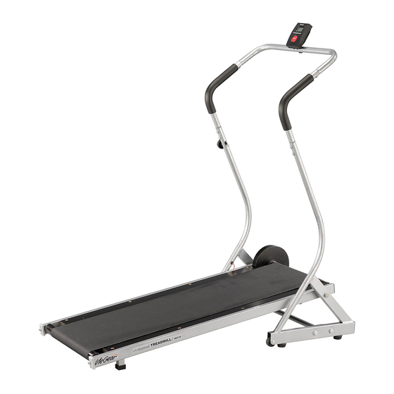
- Page 1 MANUAL TREADMILL ITEM NO.: 40115 OWNER’S MANUAL IMPORTANT: Read all instructions carefully before using this product. Retain this owner’s manual for future reference. The specifications of this product may vary from this photo, subject to change without notice. 2010, May...
-
Page 2: Table Of Contents
WARM UP AND COOL DOWN ROUTINE ----------------------------------------- 14 ONE YEAR LIMITED WARRANTY LifeGear Inc. warrants to the original purchaser that this product is free from defects in material and workmanship when used for the purpose intended, under the conditions that it has been installed and operated in accordance with LifeGear's Owner's Manual. -
Page 3: Safety Instructions
SAFETY INSTRUCTIONS Basic precautions should always be followed, including the following safety instructions when using this manual treadmill: Read all instructions before using this manual treadmill. Check every part of the equipment before exercise. If there is any defective component, replace it immediately; keep the equipment out of use until repair. Make sure all parts, bolts and nuts are well assembled and locked before exercise. -
Page 4: Operating The Computer
OPERATING THE COMPUTER SPECIFICATIONS: TIME (TMR) ------------------------------------------ 00:00-99:59 MIN: SEC SPEED (SPD) --------------------------------------- 0.0-999.9 KM/H DISTANCE (DST) ----------------------------------- 0.00-99.99 KM CALORIES (CAL) ----------------------------------- 0-9999 KCAL FUNCTIONS AND OPERATIONS: AUTO ON /OFF: When you start to exercise or press MODE button on the computer, the computer will turn on. -
Page 5: Parts List
PARTS LIST Description Qty No. Description 1 022 End Cap (□20x40) 001 Right Handlebar Support Frame 002 Left Handlebar Support Frame 1 023 Bolt M10x40 003 Handlebar Support Tube 2 024 Rear Roller Adjustment Bolt Plate 004 Computer Tube 1 025 Washer Ø6 005 Connecting Support Frame 1 026 Rear Roller Adjustment Bolt M6x55 1 027 End Cap (□25x25) -
Page 6: Hardware Packing List
HARDWARE PACKING LIST (14) Washer Ø10 (15) Bolt M10x55 (16) Bolt M6x15 6 PCS 2 PCS 4 PCS (17) Round Knob (19) Bolt M6x12 (21) Nylon Nut M10 M8x70 2 PCS 4 PCS 1 PC (23) Bolt M10x40 4 PCS TOOLS Multi Hex Tool S13, S17, S19 Allen Wrench #5... -
Page 7: Overview Drawing
OVERVIEW DRAWING... -
Page 8: Assembly Instructions
ASSEMBLY INSTRUCTIONS Tool: 21 14 2 Multi Hex Tools (S13, S17, S19) 21 14 Step 1 Attach the Connecting Support Frame (5) onto the Right/Left Handlebar Support Frames (1, 2) with four Ø10 Washers (14), four M10 Nylon Nuts (21), and four M10x40 Bolts (23). Tighten bolts and nuts with two Multi Hex Tools provided. - Page 9 Tool: Allen Wrench #5 Step 2 Attach the Handlebar Support Tube (3) onto the Right Handlebar Support Frame (1) with two M6x15 Bolts (16). Connect the Sensor Wire II (39) from the Handlebar Support Tube (3) to the Sensor Wire III (40) from the Left Handlebar Support Frame (39).
- Page 10 Tool: Allen Wrench #5 Step 3 Connect the Sensor Wire I (38) from the Computer Tube (4) to the Sensor Wire II (39) from the Handlebar Support Tube (3). Attach the Computer Tube (4) into the Handlebar Support Tubes (3) with two M6x12 Bolts (19).
- Page 11 Tool: 2 Multi Hex Tools (S13, S17, S19) Step 4 Attach the Main Frame (6) onto the Right/Left Handlebar Support Frames (1, 2) with two Ø10 Washers (14) and two M10x55 Bolts (15). Tighten bolts with two Multi Hex Tools provided.
-
Page 12: Lifting Up The Treadmill For Storage
LIFTING UP THE TREADMILL FOR STORAGE Remove the Round Knob (17) from the lower end of the Left Handlebar Support Frame (2). See Figure 1. Lift the rear end of the Main Frame (6) up in the vertical position and align Round Knob (17) hole. -
Page 13: Adjustment
ADJUSTMENT Rear Roller Adjustment Bolt Adjusting the Running Belt The Running Belt is adjusted at the factory; it may come loose during transportation and from use. After prolong use of running, the belt will stretch out. If the Running Belt is shifting to the left, using the Allen Wrench provided, turn the left Rear Roller Adjustment Bolt 1/4 turn in a clockwise direction. -
Page 14: Maintenance
MAINTENANCE Cleaning The treadmill can be cleaned with a soft clean damp cloth. Do not use abrasives or solvents on plastic parts. Please wipe your perspiration off the treadmill after each use. Be careful not get excessive moisture on the computer display panel as this might cause an electrical hazard or electronics to fail. -
Page 15: Warm Up And Cool Down Routine
WARM UP AND COOL DOWN ROUTINE A good exercise program consists of a warm-up, aerobic exercise, and a cool down. Do the entire program at least two to three times a week, resting for a day between workouts. After several months you can increase your workouts to four or five times per week. AEROBIC EXERCISE is any sustained activity that sends oxygen to your muscles via your heart and lungs. - Page 16 SIDE STRETCHES Open your arms to the side and lift them until they are over your head. Reach your right arm as far toward the ceiling as you can for one count. Repeat this action with your left arm. QUADRICEPS STRETCH With one hand against a wall for balance, reach behind you and pull your right foot up.
- Page 17 TOE TOUCHES Slowly bend forward from your waist, letting your back and shoulders relax as you stretch toward your toes. Reach as far as you can and hold for 15 counts. HAMSTRING STRETCHES Extend your right leg. Rest the sole of your left foot against your right inner thigh.
Need help?
Do you have a question about the 40115 and is the answer not in the manual?
Questions and answers