Table of Contents
Advertisement
Quick Links
Advertisement
Table of Contents

Related Manuals for LifeGear 40160


Summary of Contents for LifeGear 40160
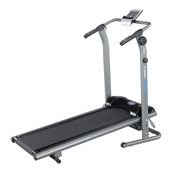
- Page 1 TREADMILL ITEM NO.: 40160 OWNER’S MANUAL IMPORTANT: Read all instructions carefully before using this product. Retain this owner’s manual for future reference. The specifications of this product may vary from this photo and are subject to change without prior notice.
-
Page 2: Table Of Contents
TABLE OF CONTENTS WARRANTY ------------------------------------------------------------------------------- 2 IMPORTANT SAFETY INSTRUCTIONS ------------------------------------------- 3 EXPLODED VIEW ----------------------------------------------------------------------- 4 PARTS LIST ------------------------------------------------------------------------------- 5 TOOL ---------------------------------------------------------------------------------------- 6 HARDWARE LIST ----------------------------------------------------------------------- 7 ASSEMBLY INSTRUCTIONS --------------------------------------------------------- 8 OPERATING THE COMPUTER ------------------------------------------------------ 15 STORAGE ---------------------------------------------------------------------------------- 16 MOVING THE TREADMILL ------------------------------------------------------------ 17 ADJUSTMENTS -------------------------------------------------------------------------- 18 LUBRICATION ---------------------------------------------------------------------------- 22 MAINTENANCE -------------------------------------------------------------------------- 23... -
Page 3: Warranty
ONE YEAR LIMITED WARRANTY LifeGear Inc. warrants to the original purchaser that this product is free from defects in material and workmanship when used for the purpose intended, under the conditions that it has been installed and operated in accordance with LifeGear's Owner's Manual. LifeGear's obligation under this warranty is limited to replacing or repairing free of charge, any parts which may prove to be defective under normal home use. -
Page 4: Important Safety Instructions
IMPORTANT SAFETY INSTRUCTIONS Basic precautions should always be followed, including the following safety instructions when using this magnetic treadmill. Read all instructions before using this magnetic treadmill. Check every part of the equipment before exercise. If there is any defective component, replace it immediately;... -
Page 5: Exploded View
EXPLODED VIEW... -
Page 6: Parts List
PARTS LIST Description Qty No. Description Hexagon Socket Pan Head Cap 001 Main Frame 1 021 Bolt M8x40 002 Base Tube 1 022 Extension Sensor Wire (1000 mm) 003 Left Upright Tube 1 023 Nylon Nut M8 004 Right Upright Tube 1 024 Sensor with Wire (210 mm) 005 Handlebar Ø28 1 025 Hand Pulse Sensor... -
Page 7: Tool
PARTS LIST Description Qty No. Description Hexagon Socket Pan Head Cap 041 Computer 1 049 Bolt M8x15 Cross Recessed Pan Head Bolt 042 Wire Grommet Ø12 4 050 M6x10 Cross Recessed Pan Head Bolt 043 Handlebar End Cap 2 051 M5x10 Hexagon Socket Pan Head Cap 044 Magnet 39.5x25x12... -
Page 8: Hardware List
HARDWARE LIST (15) Lock Knob (18) Hexagon Socket (49) Hexagon Socket 1 PC Pan Head Cap Bolt Pan Head Cap Bolt 2 PCS 6 PCS (52) Hexagon Socket (53) Washer (54) Washer 2 PCS 4 PCS Pan Head Cap 2 PCS (55) Curve Washer 4 PCS... -
Page 9: Assembly Instructions
ASSEMBLY INSTRUCTIONS Step 1 Attach both Left/Right Upright Tubes (3, 4) onto the Base Tube (2) with six Hexagon Socket Pan Head Cap Bolts (49), four Washers (54), and two Curve Washers (55). Semi-tighten bolts with the Allen Wrench with Phillips Screwdriver provided. NOTE: DO NOT FULLY TIGHTEN BOLTS IN STEP 1 UNTIL THE STEP 5 IS COMPLETE. - Page 10 Step 2-1 Step 2-2 Turn the Tension Control Knob Remove the B (Nut) from the (47) clockwise to the highest level resistance cable of the Tension (8-Level). Control Knob (47). Step 2-4 Step 2-3 Put the A (cable end of resistance Insert the resistance cable of the cable) into the cable lock of Tension Control Knob (47) to the...
- Page 11 50 56 Step 3 Remove four Cross Recessed Pan Head Bolts (50) and four Washers (56) from the Main Frame (1). Remove bolts with the Allen Wrench with Phillips Screwdriver provided. Attach the Plastic Cover (38) onto the Main Frame (1) with four Cross Recessed Pan Head Bolts (50) and four Washers (56) that were removed.
- Page 12 Step 4 It is recommended to have a second person assist with this step. One person should lift the front end of the Main Frame (1) up and align bolt holes while the other person tightens the bolts. Position the front end of the Main Frame (1) up onto the Left/Right Upright Tubes (3, 4) and align bolt holes.
- Page 13 Step 5 Attach the Handlebar (5) onto the both Left/Right Upright Tubes (3, 4) with two Hexagon Socket Pan Head Cap Bolts (18) and two Curve Washers (55). Tighten bolts with the Allen Wrench with Phillips Screwdriver provided. NOW PLEASE FULLY TIGHTEN ALL BOLTS AND LOCK KNOB INSTALLED IN STEP 1 AND STEP 4 WITH THE ALLEN WRENCH WITH PHILLIPS SCREWDRIVER PROVIDED.
- Page 14 Step 6 Connect the Extension Sensor Wire (22) from the Left Upright Tube (3) to the Extension Sensor Wire I (17) from the Handlebar (5). Step 7 Remove two Cross Recessed Pan Head Bolts (51) from the Computer (41). Remove bolts with the Allen Wrench with Phillips Screwdriver provided.
- Page 15 17 26 Step 8 A. Insert the wires that come from the Computer (41) through into the hole on the plate of the Handlebar (5). B. Connect the Extension Sensor Wire I (17) and Hand Pulse Sensor Wires (26) from the Handlebar (5) to the wires that come from the Computer (41).
-
Page 16: Operating The Computer
OPERATING THE COMPUTER USING YOUR COMPUTER The computer can be activated by pressing the MODE button or by running. If you leave the equipment idle for 4-5 minutes, the power will turn off automatically. BUTTON FUNCTIONS: Press the MODE button to select each function of the computer. Press and hold the MODE button for 4 seconds to reset all data values to zero except the ODO (ODOMETER) data values. -
Page 17: Storage
STORAGE Remove the Lock Knob (15) from the lower end of the Right Upright Tube (4). Lift the rear end of the Main Frame (1) up in the vertical position and align Lock Knob hole. Tighten the Lock Knob (15) by turning it in a clockwise direction into the holes on the Right Upright Tube (4) and Main Frame (1). -
Page 18: Moving The Treadmill
MOVING THE TREADMILL Handlebar The unit can be carefully tilted onto its transport wheels for easy moving and storage. With the treadmill in the folded locked position, firmly grasp the both Handlebars with both hands. Next, carefully tilt the treadmill back until it rolls freely on the transport wheels. CAUTION: Do not attempt to move the treadmill while it is in the unfolded position. -
Page 19: Adjustments
ADJUSTMENTS Tension Control Knob Adjusting the Tension Control Knob To increase the tension, turn the Tension Control Knob in a clockwise direction. To decrease the tension, turn the Tension Control Knob in a counterclockwise direction. Incline Adjuster Incline Angle 1 Incline Angle 2 Incline Angle 3 Adjusting the Incline Adjuster... - Page 20 Adjusting the Tension The user can set the desired tension power according to the figure as below: To decrease the tension, turn the To increase the tension, turn the Bolt (13) in a clockwise direction. Bolt (13) in a counterclockwise direction.
- Page 21 Adjusting the Running Belt The running belt is initially set and adjusted at the factory. However it may come loose during transportation and/or during use. It is recommended that the user run on the center of the running belt. After prolonged use, the belt will begin to stretch out. It is suggested that the user always to walk or run on the central area.
- Page 22 If the running belt begins to shift to the right, the user can stand on the Main Frame and hold the handlebar with both hands. Then use your left foot to run on the left side of the running belt. You should see the running belt start to correct itself by moving back towards the center.
-
Page 23: Lubrication
LUBRICATION Lubricating under the running belt will ensure superior performance and extend its life expectancy. After the first 25 hours of use (or 2-3 months) apply some lubricant, and repeat for every following 50 hours of use (or 5-8 months). How to check running belt for proper lubrication Lift one side of the running belt and feel the top surface of the running deck. -
Page 24: Maintenance
MAINTENANCE Cleaning The magnetic treadmill can be cleaned with a soft clean damp cloth. Do not use abrasives or solvents on plastic parts. Please wipe your perspiration off the treadmill after each use. Be careful not to get excessive moisture on the computer display panel as this might cause an electrical hazard or electronics to fail. -
Page 25: Warm Up And Cool Down Routine
WARM UP AND COOL DOWN ROUTINE The WARM-UP is an important part of any workout. The purpose of warming up is to prepare your body for exercise and to minimize injuries. Warm up for two to five minutes before aerobic exercising. It should begin every session to prepare your body for more strenuous exercise by heating up and stretching your muscles, increasing your circulation and pulse rate, and delivering more oxygen to your muscles. - Page 26 QUADRICEPS STRETCH With one hand against a wall for balance, reach behind you and pull your right foot up. Bring your heel as close to your buttocks as possible. Hold for 15 counts and repeat with left foot. INNER THIGH STRETCH Sit with the soles of your feet together and your knees pointing outward.
Need help?
Do you have a question about the 40160 and is the answer not in the manual?
Questions and answers