Table of Contents
Advertisement
Quick Links
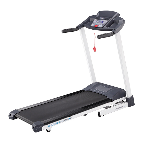
SYMPHONY PRO
PROGRAMMABLE MOTORIZED
TREADMILL
ITEM NO: 97655
OWNER'S MANUAL
IMPORTANT: Read all instructions carefully before using this product. Retain this
owner's manual for future reference.
The specifications of this product may vary from this photo and are subject to change
without prior notice.
2018, Feb.
Advertisement
Table of Contents

Related Manuals for LifeGear SYMPHONY PRO 97655


Summary of Contents for LifeGear SYMPHONY PRO 97655
- Page 1 SYMPHONY PRO PROGRAMMABLE MOTORIZED TREADMILL ITEM NO: 97655 OWNER’S MANUAL IMPORTANT: Read all instructions carefully before using this product. Retain this owner’s manual for future reference. The specifications of this product may vary from this photo and are subject to change without prior notice.
-
Page 2: Table Of Contents
TABLE OF CONTENTS WARRANTY ------------------------------------------------------------------------------ 2 IMPORTANT SAFETY INSTRUCTIONS ------------------------------------------- 3 PARTS LIST -------------------------------------------------------------------------------- 5 HARDWARE LIST ------------------------------------------------------------------------ 7 TOOLS --------------------------------------------------------------------------------------- 7 EXPLODED VIEW ------------------------------------------------------------------------ 8 ASSEMBLY INSTRUCTIONS --------------------------------------------------------- 9 LIFTING UP & SETTING DOWN THE TREADMILL ----------------------------- 13 MOVING THE TREADMILL ------------------------------------------------------------ 14 OPERATING THE COMPUTER ------------------------------------------------------ 15 ERROR MESSAGES -------------------------------------------------------------------- 23 CARE, MAINTENANCE &... -
Page 3: Warranty
ONE YEAR LIMITED WARRANTY LifeGear Inc. warrants to the original purchaser that this product is free from defects in material and workmanship when used for the purpose intended, under the conditions that it has been installed and operated in accordance with LifeGear's Owner's Manual. -
Page 4: Important Safety Instructions
IMPORTANT SAFETY INSTRUCTIONS Basic precautions, including the following important safety instructions should always be followed when using this treadmill. Read all instructions before using this treadmill. DANGER: To reduce the risk of electric shock, always unplug the treadmill from the electrical outlet immediately after using and before cleaning, assembling, or servicing the treadmill. - Page 5 Always hold on to the handrails while using the treadmill. Always make sure the storage latch is in place when folding and moving the treadmill. Do not leave children who are under 12 years-old unsupervised near or on the ...
-
Page 6: Parts List
PARTS LIST Description Qty No. Description Cross Recessed Round Head 001 Base Frame 1 024 Tapping Screw M4x15 Cross Recessed Truss Head 002 Main Frame 1 025 Tapping Screw M4x10 003 Left Handlebar Support Tube 1 026 Nylon Nut M10 004 Right Handlebar Support Tube 1 027 Nylon Nut M8 005 Incline Bracket... - Page 7 PARTS LIST Description Qty No. Description Hand Pulse Sensor with Incline 047 Transport Wheel Ø46xØ8.5x18.5 2 065 Control Buttons Hand Pulse Sensor with Speed 048 Transport Wheel Ø51xØ8.5x22 2 066 Control Buttons 049 Handlebar End Cap (20x40) 2 067 Rectangular End Cap (20x40) Handlebar Foam Grip 2 068 Wire Grommet Ø31xT5x280...
-
Page 8: Hardware List
HARDWARE LIST (14) Hexagon Socket (20) Cross Recessed (30) Washer Button Head Bolt Truss Head Bolt 8 PCS 8 PCS 4 PCS TOOLS Hex Socket Wrench with Phillips Screwdriver 1 PC 5 mm Allen Wrench 6 mm Allen Wrench 1 PC 1 PC... -
Page 9: Exploded View
EXPLODED VIEW... -
Page 10: Assembly Instructions
ASSEMBLY INSTRUCTIONS 5 mm Allen Wrench 14 30 5 mm Allen Wrench Step 1 Attach the Left Handlebar Support Tube (3) to the Base Frame (1) with four Hexagon Socket Button Head Bolts (14) and four Washers (30). Semi-tighten bolts with the 5 mm Allen Wrench provided. - Page 11 NOTE: Position the wire ring terminal connector under the lug of the left handlebar support tube and align bolt hole. Step 2 It is recommended to have a second person assist with this step. One person should hold the Computer Console (33) in place while the other person connects the wires. Connect the Hand Pulse Sensor wire with Incline Control Button Wire (65) from the Left Handlebar Support Tube (3) to the wires that come from the Computer Console (33).
- Page 12 Step 3 Remove two Cross Recessed Truss Head Bolts (22) from both Left/Right Handlebar Support Tubes (3, 4). Remove bolts with the Hex Socket Wrench with Phillips Screwdriver provided. Install two Left and Right Fenders (38, 39) onto the Left/Right Handlebar Support Tubes (3, 4) using two Cross Recessed Truss Head Bolts (22) that were removed.
- Page 13 Tool: 6 mm Allen Wrench Step 5 The running belt has been adjusted to the running deck at the factory before it was shipped. At times the running belt may get slippery during shipment. After the treadmill is completely assembled, use the 6 mm Allen Wrench to turn the both left and right rear roller adjustment bolts 1/4 turn clockwise before using the treadmill.
-
Page 14: Lifting Up & Setting Down The Treadmill
LIFTING UP & SETTING DOWN THE TREADMILL LIFTING UP THE TREADMILL Firmly grasp the rear end of the Main Frame with both hands. Carefully lift the end of the treadmill up into the upright position until the Foot Lock Latch engages and securely locks the main frame into position. -
Page 15: Moving The Treadmill
MOVING THE TREADMILL Handlebar Transport Wheel The unit can be carefully tilted onto its transport wheels for easy moving and storage. With the treadmill in the folded locked position (foot lock latch is engaged), firmly grasp the Handlebars with both hands and place one foot onto the Transport Wheel. Next, carefully tilt the treadmill back until it rolls freely on the transport wheels. -
Page 16: Operating The Computer
OPERATING THE COMPUTER Flip the Master Power Switch that is located at the front of the treadmill to the ON position. Before beginning a workout session ensure that the Safety Tether Key is properly placed onto the Computer Console and the Safety Clip is securely attached to an article of your clothing. - Page 17 MODE: Press the MODE button to select one of the functions (TIME, DISTANCE, or CALORIE) for setting exercise target in Manual Program Mode before training. Press the MODE button to select a intensity level from L-1 to L-8 in Pre-Set Program Mode (P01-P08) before training.
-
Page 18: Display Functions
DISPLAY FUNCTIONS: TIME: Displays your elapsed workout time in minutes and seconds. SPEED: Displays the current training speed. DISTANCE: Displays the accumulative distance travelled during your workout. CALORIE: Displays the total calories burned during your workout. INCLINE: Displays the incline level from the minimum 0-level (L 0) to the maximum 15-level (L 15). - Page 19 SPEED ∨ button to change the time setting. The per-set elapsing time of each per-set program is 30: 00 minutes. Press the START button to confirm and start your workou, the computer screen will countdown 3 seconds before the running belt starts moving. The running speed and incline level will change automatically during the workout (as shown below).
- Page 20 P3. FAT BURN INTERVAL INCLINE LEVEL SPEED (KPH) INCLINE LEVEL SPEED (KPH) INCLINE LEVEL SPEED (KPH) INCLINE LEVEL SPEED (KPH) INCLINE LEVEL SPEED (KPH) INCLINE LEVEL SPEED (KPH) INCLINE LEVEL SPEED (KPH) INCLINE LEVEL SPEED (KPH) P4. POWER WALK INTERVAL SPEED (KPH) SPEED (KPH) SPEED (KPH)
- Page 21 P5. INTERVAL INTERVAL SPEED (KPH) SPEED (KPH) SPEED (KPH) SPEED (KPH) SPEED (KPH) SPEED (KPH) SPEED (KPH) SPEED (KPH) P6. ROLLING INTERVAL SPEED (KPH) SPEED (KPH) SPEED (KPH) SPEED (KPH) SPEED (KPH) SPEED (KPH) SPEED (KPH) SPEED (KPH) P7. MOUNTAIN CLIMB INTERVAL INCLINE LEVEL SPEED (KPH)
- Page 22 P8. HILL RUN INTERVAL INCLINE LEVEL SPEED (KPH) INCLINE LEVEL SPEED (KPH) INCLINE LEVEL SPEED (KPH) INCLINE LEVEL SPEED (KPH) INCLINE LEVEL SPEED (KPH) INCLINE LEVEL SPEED (KPH) INCLINE LEVEL SPEED (KPH) INCLINE LEVEL SPEED (KPH) TRAINING IN BODY FAT CALCULATOR PROGRAM MODE: Press the PROG (PROGRAM) button to select FAT (Body Fat Calculator Program).
- Page 23 SPEED ▲ SPEED ▼ INCLINE ▲ INCLINE ▼ INCLINE ▲: Press the INCLINE ▲ button on the Left Handrail to increase incline level. INCLINE ▼: Press the INCLINE ▼ button on the Left Handrail to decrease incline level. SPEED ▲: Press the SPEED ▲ button on the Right Handrail to increase speed. SPEED ▼: Press the SPEED ▼...
-
Page 24: Error Messages
ERROR MESSAGES Error Messages Potential Cause Things to Check The computer console did not Please re-check and/or re-connect receive any feedback within the cable joint between the 30 seconds from the power computer console and the power control board. control board. The power control board did Please re-check and/or re-connect not receive any input voltage... -
Page 25: Care, Maintenance & Troubleshooting Guide
CARE, MAINTENANCE & TROUBLESHOOTING GUIDE WARNING: To prevent electrical shock, please turn off and unplug the treadmill before cleaning or performing routine maintenance. WARNING:Always check the wear and tear components like foot lock latch tube and running belt to prevent injury. CLEANING After each exercise, ensure that the unit is wiped down and any sweat is removed from the unit. -
Page 26: Belt Adjustment
BELT ADJUSTMENT The running belt is pre-adjusted to the running deck at the factory, but after prolonged use it can stretch and require readjustment. To adjust the belt, turn on the main power switch of the treadmill and let the belt run at a speed of 8-10 KPH. Use the 6 mm Allen Wrench provided to turn the rear roller adjustment bolts in order to centre the belt. -
Page 27: Lubrication
LUBRICATION Lubricating under the running belt will ensure superior performance and extend its life expectancy. After the first 25 hours of use (or 2-3 months) apply some lubricant, and repeat for every following 50 hours of use (or 5-8 months). How to check running belt for proper lubrication Lift one side of the running belt and feel the top surface of the running deck. -
Page 28: Warm Up And Cool Down Routine
WARM UP AND COOL DOWN ROUTINE The WARM-UP is an important part of any workout. The purpose of warming up is to prepare your body for exercise and to minimize injuries. Warm up for two to five minutes before aerobic exercising. It should begin every session to prepare your body for more strenuous exercise by heating up and stretching your muscles, increasing your circulation and pulse rate, and delivering more oxygen to your muscles. - Page 29 QUADRICEPS STRETCH With one hand against a wall for balance, reach behind you and pull your right foot up. Bring your heel as close to your buttocks as possible. Hold for 15 counts and repeat with left foot. INNER THIGH STRETCH Sit with the soles of your feet together and your knees pointing outward.
Need help?
Do you have a question about the SYMPHONY PRO 97655 and is the answer not in the manual?
Questions and answers