Table of Contents

Related Manuals for FLIR ThermoVision Micron


Summary of Contents for FLIR ThermoVision Micron
- Page 1 ThermoVision® Micron/A10 User’s Guide 412-0006-10 Version 130 ThermoVision® Micron/A10 Camera User’s Guide 412-0006-10 Version FLIR Systems Indigo Operations 70 Castilian Dr. Goleta, CA 93117-3027 805 964-9797 FAX 805 685-2711 www.indigosystems.com...
-
Page 2: Table Of Contents
ThermoVision® Micron/A10 User’s Guide 412-0006-10 Version 130 TABLE OF CONTENTS INTRODUCTION......................... 4 MICRON/A10 SPECIFICATIONS ..................4 OPTIONAL MICRON/A10 FEATURES................5 UNPACKING YOUR MICRON/A10 CAMERA .............. 6 OPTIONAL MICRON/A10 ACCESSORIES..............7 OVERVIEW OF THE MICRON/A10 ELECTRICAL INTERFACE......8 ..........................8 NPUT OWER ...................... - Page 3 ThermoVision® Micron/A10 User’s Guide 412-0006-10 Version 130 Cautions: • Do not remove the camera cover. Disassembly of the camera (including removal of the cover) can cause permanent damage and will void the warranty. • Operating the camera outside of the specified input voltage range or the specified operating temperature range can cause permanent damage.
-
Page 4: Introduction
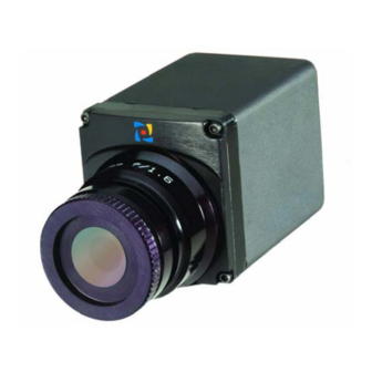
ThermoVision® Micron/A10 User’s Guide 412-0006-10 Version 130 1 INTRODUCTION The ThermoVision® Micron or ThermoVision® A10 is a long-wavelength (7.5 – 13.5 microns) uncooled microbolometer camera designed for infrared imaging applications that demand absolute minimum size, weight, and power consumption. It is available with five different lens options: 8.5mm focal length (55°... -
Page 5: Optional Micron/A10 Features
ThermoVision® Micron/A10 User’s Guide 412-0006-10 Version 130 3 OPTIONAL MICRON/A10 FEATURES • Extended input voltage range: 7.5V – 30.0V (standard range is 3.5V – 9.0V) • Extended operating temperature range: -40 C to +55 C (standard range 0 C to +40 •... -
Page 6: Unpacking Your Micron/A10 Camera
ThermoVision® Micron/A10 User’s Guide 412-0006-10 Version 130 4 UNPACKING YOUR MICRON/A10 CAMERA The items shown in Figure 2 come standard in your Micron/A10 Camera package. If there is any discrepancy between this list and the contents of your camera package, please contact Indigo Systems Customer Support immediately at (805) 964-9797. -
Page 7: Optional Micron/A10 Accessories
ThermoVision® Micron/A10 User’s Guide 412-0006-10 Version 130 5 OPTIONAL MICRON/A10 ACCESSORIES • 6”, 3’, 10’ or 25’ interface cable • 3’, or 10’ Power / Video Cable (replaces Interface Cable and I/O Module) • Digital data serial-to-parallel module (parallel data cable sold separate) •... -
Page 8: Overview Of The Micron/A10 Electrical Interface
ThermoVision® Micron/A10 User’s Guide 412-0006-10 Version 130 6 OVERVIEW OF THE MICRON/A10 ELECTRICAL INTERFACE The Micron/A10 camera provides all input/output signals via a single 18-pin connector. The signals on this connector include input power, analog video output, serial communication channel for command and control and the digital data output. Note: See the Interface Control Document (ISC doc. -
Page 9: Analog Video Output
ThermoVision® Micron/A10 User’s Guide 412-0006-10 Version 130 Analog Video Output The video output of the Micron/A10 camera can be configured to either NTSC or PAL- compatible. In either case, the output is intended to drive a 75-ohm load impedance. See Table 2 for a list of other relevant video parameters. -
Page 10: Basic Operation Of The Micron/A10 Camera
ThermoVision® Micron/A10 User’s Guide 412-0006-10 Version 130 BASIC OPERATION OF THE MICRON/A10 CAMERA Note: If you are using the Ethernet Module, environmental enclosure, integral battery pack, Remote Control Panel or Hotshoe adapter additional instructions may also be provided. 1. If you intend to mount the camera on a tripod, attach the tripod adapter plate to the bottom of your Micron/A10 camera using a 5/64 “... - Page 11 ThermoVision® Micron/A10 User’s Guide 412-0006-10 Version 130 Figure 4: Connecting the Interface Cable to the Micron/A10 To electrical outlet To video monitor To PC (only required if using RS-232 interface.) Figure 5: Micron/A10 after cabling...
- Page 12 ThermoVision® Micron/A10 User’s Guide 412-0006-10 Version 130 Figure 6: Micron/A10 and Ethernet Module Micron/A10 Ethernet To video monitor interface cable Laptop with standard RJ45 connector Standard CAT-5 LAN cable To Indigo 9-Volt power supply Figure 7: Laptop connected to Micron/A10 and Ethernet Module...
- Page 13 ThermoVision® Micron/A10 User’s Guide 412-0006-10 Version 130 Figure 8: Micron/A10 and Firewire Module To video monitor To Indigo 9-Volt power supply Laptop with built-in 4-pin Firewire port 6-pin to 4-pin adapter Figure 9: Laptop connected to Micron/A10 and Firewire Module...
-
Page 14: Remote Control Of The Micron/A10 Camera
2. The installation program will present instructions for installing the application to your hard drive. By default, the setup wizard will install the application in the directory C:\ProgramFiles\Indigo\ThermoVision Micron, and the filename is Micron Control Panel.exe. Note: If using the Ethernet Module further steps are required to install. Please refer to the included install guide ISC doc. -
Page 15: Connecting Micron /A10 To Apc Via The I/O Module
ThermoVision® Micron/A10 User’s Guide 412-0006-10 Version 130 Connecting Micron/A10 to a PC via the I/O Module 1. Follow the steps shown in Section 0 for basic operation of the Micron/A10 camera. After verifying that the camera is producing an image, power down the camera. 2. -
Page 16: Connecting Micron /A10 To Apc Via The Ethernet Module
ThermoVision® Micron/A10 User’s Guide 412-0006-10 Version 130 Connecting Micron/A10 to a PC via the Ethernet Module 1. Follow the steps shown in Section 0 for basic connection of the Micron/A10 camera and the Ethernet Module. 2. Connect one end of a CAT5 cable to the RJ45 port on the Ethernet Module, as shown in Figure 11. -
Page 17: Connecting Micron/A10 To A Pc Via The Firewire(Ieee-1394) Module
ThermoVision® Micron/A10 User’s Guide 412-0006-10 Version 130 7. If you see the window shown in Figure 14, verify that the Ethernet Module LED is powered on and connected to the PC. Then select the Ethernet Comm interface option and then hit the “Connect” button. If the Control Panel successfully links to the camera, skip ahead the section below titled “Operation of the Micron/A10 Control Panel”. - Page 18 ThermoVision® Micron/A10 User’s Guide 412-0006-10 Version 130 Figure 16: IEEE-1394 Cable connect to Firewire Module 12. Assuming the Control Panel software is already installed on the PC (see installation instructions above), execute the software. 13. The Control Panel software will attempt to automatically identify the port upon which the camera is installed.
-
Page 19: Troubleshooting The Command & Control Link
ThermoVision® Micron/A10 User’s Guide 412-0006-10 Version 130 Figure 17: Control Panel Select Firewire communication 15. Following Step 14, if you are still having trouble communicating with the camera then refer to the guidelines in the following section, titled “Troubleshooting the Command & Control Link Troubleshooting the Command &... -
Page 20: Operation Of The Micron/A10 Control Panel
ThermoVision® Micron/A10 User’s Guide 412-0006-10 Version 130 Operation of the Micron/A10 Control Panel When the Control Panel successfully links to the camera, you will see the window shown in Figure 18. The Control Panel provides four tabs as well as six menu options across the top. It also provides a text message in the lower-left corner showing status information reported back from the camera after each command. - Page 21 ThermoVision® Micron/A10 User’s Guide 412-0006-10 Version 130 1. Smart-Scene. In Smart-Scene mode, image contrast and brightness are optimized automatically as the scene varies. This mode provides an Automatic Gain Control (AGC) which is based on a histogram-equalization (HEQ) algorithm. The slider above allows for the “Max Gain”...
- Page 22 ThermoVision® Micron/A10 User’s Guide 412-0006-10 Version 130 Dynamic-Range-Control Mode: Micron/A10 provides a low-temperature (high-sensitivity) state intended for imaging scenes that are nominally less than 150 C (302 F) as well as a high-temperature (low-sensitivity) state intended for imaging up to 500 C (932 F).
-
Page 23: Control Panel Video Tab
ThermoVision® Micron/A10 User’s Guide 412-0006-10 Version 130 2. Manual. In Manual FFC mode, the camera does not perform FFC automatically based on specified values of temperature change or expired time. Note: Even in manual FFC mode, Micron/A10 will perform automatic FFC when it changes between low-temperature and high-temperature states. - Page 24 ThermoVision® Micron/A10 User’s Guide 412-0006-10 Version 130 Video Mode: Three Video modes are provided for configuring the camera output: 1. Real-Time. In this mode, the camera provides streaming thermal imagery in real-time. 2. Freeze-Frame. The camera freezes the image at the moment this mode is selected, providing the same frame continuously.
- Page 25 ThermoVision® Micron/A10 User’s Guide 412-0006-10 Version 130 displayed on an analog video monitor, particularly if the optional Isotherm feature is enabled or any Image Optimization mode other than Smart-scene is selected. pix(0,0) = 0 pix(x,y) = y pix(0,128) = 128 Figure 21: Vertical shade test pattern (Digital values shown apply to the optional 14-bit digital data stream.) Image-Orientation Mode: Two Image-Orientation modes are provided:...
- Page 26 ThermoVision® Micron/A10 User’s Guide 412-0006-10 Version 130 On-Screen-Symbol Modes: Micron/A10 uses on-screen symbols for displaying important camera status. Specifically, the following indicators are provided: a. Overtemp: displayed when the camera is operating above 55 C, the maximum specified temperature. b. Low Voltage: displayed when the camera input voltage is below 3.5V (or 7.5V with the extended voltage-range option).
-
Page 27: Control Panel Digital Tab
ThermoVision® Micron/A10 User’s Guide 412-0006-10 Version 130 7.1.3 Control Panel Digital Tab The Digital Tab on the Control Panel, shown in Figure 23, provides the ability to modify the Digital Output mode (if the camera includes the optional digital data channel). Figure 23: Micron/A10 Control Panel, Digital Tab Digital Output Modes: The Micron/A10 provides a digital data channel with two selectable modes:... -
Page 28: Control Panel Advanced Tab
ThermoVision® Micron/A10 User’s Guide 412-0006-10 Version 130 7.1.4 Control Panel Advanced Tab The Advanced Tab on the Control Panel, shown in Figure 24, provides the ability to control several advanced camera features as well as the optional spot meter and isotherm modes. Figure 24: Micron/A10 Control Panel, Advanced Tab Spot Meter Modes: The A10 camera version provides an optional spot-meter feature. - Page 29 ThermoVision® Micron/A10 User’s Guide 412-0006-10 Version 130 Isotherm Modes: Micron/A10 provides a Isotherm capability in which sufficiently hot objects are colored either yellow or red on the displayed image. Figure 25 shows an example image with isotherms enabled. The figure shows a light shade along the perimeter of the square to be yellow and the darker shade on the interior is red.
-
Page 30: Control Panel Menu Options
ThermoVision® Micron/A10 User’s Guide 412-0006-10 Version 130 Read Camera Temperature. The Read Camera Temperature command updates the adjacent display window with a measurement of camera case temperature. The temperature is measured on the camera’s metal mounting surface. Comm. Test. The Comm. Test command is a diagnostic feature for verifying the communication link between the Control Panel and the Micron/A10 camera. - Page 31 ThermoVision® Micron/A10 User’s Guide 412-0006-10 Version 130 current camera state correctly. For example, use Refresh if you connect the Omega camera to the PC after the Control Panel software is already running. Comm. The Comm. command provides the ability to specify a different Comm Interface and port for camera communication.
- Page 32 ThermoVision® Micron/A10 User’s Guide 412-0006-10 Version 130 Figure 27: Micron/A10 About Window...
-
Page 33: Micron/A10 Digital Data Channel
ThermoVision® Micron/A10 User’s Guide 412-0006-10 Version 130 8 MICRON/A10 DIGITAL DATA CHANNEL Micron/A10 provides a digital data channel that provides thermal imagery in digital format. This channel can be used in conjunction with commercially-available digital frame grabbers, digital displays, or custom receive electronics. Again, for Micron/A10 users with embedded or specialty applications that require custom control software, a Software Developer’s Kit (SDK) and an Interface Control Document (ICD) are available to support your development efforts. -
Page 34: Using The Digital Data Channel
ThermoVision® Micron/A10 User’s Guide 412-0006-10 Version 130 Using the Digital Data Channel Note: The following instructions assume that you have purchased the optional serial-to-parallel- out (SIPO) accessory module with parallel data cable. If you are using the Ethernet module, or the Firewire module, follow the instructions in the section Connecting Micron/A10 to a PC via the Firewire(IEEE-1394). - Page 35 ThermoVision® Micron/A10 User’s Guide 412-0006-10 Version 130 Figure 28: Micron/A10 11-mm lens configuration...
- Page 36 ThermoVision® Micron/A10 User’s Guide 412-0006-10 Version 130 Figure 29: Micron/A10 18-mm lens configuration...
- Page 37 ThermoVision® Micron/A10 User’s Guide 412-0006-10 Version 130 Figure 30: Micron/A10 30-mm lens configuration...
-
Page 39: Appendix A: Pin-Out Definitions
ThermoVision® Micron/A10 User’s Guide 412-0006-10 Version 130 APPENDIX A: PIN-OUT DEFINITIONS Camera I/O Table A1: Camera Connector Pin-Outs Pin # Signal Name Signal Definition 1, 3 input power 2, 4 PWR_RTN input power return spare (do not connect) 6, 10 DGND Digital Ground VIDEO... -
Page 40: I/O Module
ThermoVision® Micron/A10 User’s Guide 412-0006-10 Version 130 I/O Module Camera Connector: Same as camera connector. See Table A2 for valid mates. Power Connector: Mates to Switchcraft S760 Miniature Power Plug. Video Connector: Mates to 75Ω BNC twist-on plug. Serial Connector: Mates to DB9 Male. Digital Data Connector: Mates to Three-Row DB15 Female. - Page 41 ThermoVision® Micron/A10 User’s Guide 412-0006-10 Version 130 Table A6: I/O Module Digital Data Connector Pin-Out Pin # Signal Name Signal Definition DATA_SYNC Digital data sync (LVDS high) DATA_OUT+ Digital data output channel (LVDS high) DATA_CLK+ Digital output channel clock (LVDS high) DATA_SYNC- Digital data sync (LVDS low) DATA_OUT-...
Need help?
Do you have a question about the ThermoVision Micron and is the answer not in the manual?
Questions and answers