FLIR EX series User Manual
Hide thumbs
Also See for EX series:
- Getting started (122 pages) ,
- User manual (118 pages) ,
- Getting started manual (114 pages)
Table of Contents
Advertisement
Quick Links
Advertisement
Table of Contents

Related Manuals for FLIR EX series


Summary of Contents for FLIR EX series
- Page 1 User’s manual FLIR Ex series...
- Page 3 User’s manual FLIR Ex series #T559828; r.18043/22369; en-US...
-
Page 5: Table Of Contents
6.4.2 Explanation..............11 Operation ..................12 Charging the battery ..............12 7.1.1 Charging the battery using the FLIR power supply ....12 7.1.2 Charging the battery using the FLIR stand-alone battery charger..............12 7.1.3 Charging the battery using a USB cable ......12 Turning on and turning off the camera.......... - Page 6 Table of contents 7.5.1 General..............13 7.5.2 Procedure ..............13 Deleting all images..............14 7.6.1 General..............14 7.6.2 Procedure ..............14 Measuring a temperature using a spotmeter ......... 14 7.7.1 General..............14 7.7.2 Procedure ..............14 Measuring the hottest temperature within an area ......14 7.8.1 General..............
- Page 7 12.4.1 General..............42 12.4.2 Figure ................ 42 12.5 Draft ..................43 12.5.1 General..............43 12.5.2 Figure ................ 43 About FLIR Systems ................ 44 13.1 More than just an infrared camera ..........45 13.2 Sharing our knowledge ............45 13.3 Supporting our customers............45 13.4...
- Page 8 Table of contents 17.3 Blackbody radiation..............58 17.3.1 Planck’s law ..............59 17.3.2 Wien’s displacement law..........60 17.3.3 Stefan-Boltzmann's law ..........61 17.3.4 Non-blackbody emitters..........62 17.4 Infrared semi-transparent materials..........64 The measurement formula..............65 Emissivity tables ................69 19.1 References................
-
Page 9: Disclaimers
(“MS”). Those installed software products of MS origin, as well manship and provided that it is returned to FLIR Systems within the said one- as associated media, printed materials, and “online” or electronic docu- year period. -
Page 10: Safety Information
Applicability: Cameras with one or more batteries. Do not attach the batteries directly to a car’s cigarette lighter socket, unless FLIR Systems supplies a specific adapter to connect the batteries to a cigarette lighter socket. Damage to the batteries can occur. - Page 11 Safety information CAUTION Applicability: Cameras with one or more batteries. Do not make holes in the battery with objects. Damage to the battery can occur. CAUTION Applicability: Cameras with one or more batteries. Do not hit the battery with a hammer. Damage to the battery can occur. CAUTION Applicability: Cameras with one or more batteries.
- Page 12 Safety information CAUTION Applicability: Cameras with one or more batteries. The temperature range through which you can remove the electrical power from the battery is -15°C to +50°C (+5°F to +122°F), unless other information is specified in the user documentation or technical data.
-
Page 13: Notice To User
3.7 Important note about this manual FLIR Systems issues generic manuals that cover several cameras within a model line. This means that this manual may contain descriptions and explanations that do not apply to your particular camera model. -
Page 14: Customer Help
Customer help 4.1 General For customer help, visit: http://support.flir.com 4.2 Submitting a question To submit a question to the customer help team, you must be a registered user. It only takes a few minutes to register online. If you only want to search the knowledgebase for existing questions and answers, you do not need to be a registered user. -
Page 15: Downloads
• The communication protocol, or method, between the camera and your device (for ex- ample, HDMI, Ethernet, USB, or FireWire) • Device type (PC/Mac/iPhone/iPad/Android device, etc.) • Version of any programs from FLIR Systems • Full name, publication number, and revision number of the manual 4.3 Downloads On the customer help site you can also download the following: •... -
Page 16: Quick Start Guide
• Charge the battery using a USB cable connected to a computer. NOTE Charging the camera using a USB cable connected to a computer takes considerably longer than using the FLIR power supply or the FLIR stand-alone battery charger. 2. Push the On/off button to turn on the camera. -
Page 17: Description
Description 6.1 Camera parts 6.1.1 Figure 6.1.2 Explanation 1. Digital camera lens. 2. Infrared lens. 3. Lever to open and close the lens cap. 4. Trigger to save images. 5. Battery. 6.2 Keypad 6.2.1 Figure 6.2.2 Explanation 1. Camera screen. #T559828;... -
Page 18: Connectors
Charging the camera using a USB cable connected to a computer takes considerably longer than using the FLIR power supply or the FLIR stand-alone battery charger. • Moving images from the camera to a computer for further analysis in FLIR Tools. NOTE Install FLIR Tools on your computer before you move the images. -
Page 19: Screen Elements
Description 6.4 Screen elements 6.4.1 Figure 6.4.2 Explanation 1. Main menu toolbar. 2. Submenu toolbar. 3. Spotmeter. 4. Result table. 5. Status icons. 6. Temperature scale. #T559828; r.18043/22369; en-US... -
Page 20: Operation
To charge the camera, the computer must be turned on. • Charging the camera using a USB cable connected to a computer takes considerably longer than using the FLIR power supply or the FLIR stand-alone battery charger. 7.2 Turning on and turning off the camera • Push the button to turn on the camera. -
Page 21: Saving An Image
Operation 7.3 Saving an image 7.3.1 General You can save multiple images to the internal camera memory. 7.3.2 Image capacity Approximately 500 images can be saved to the internal camera memory. 7.3.3 Naming convention The naming convention for images is FLIRxxxx.jpg, where xxxx is a unique counter. 7.3.4 Procedure Follow this procedure: 1. -
Page 22: Deleting All Images
Operation 5. On the toolbar, select Delete 7.6 Deleting all images 7.6.1 General You can delete all images from the internal camera memory. 7.6.2 Procedure Follow this procedure: 1. Push the center of the navigation pad. This displays a toolbar. 2. -
Page 23: Hiding Measurement Tools
Operation 7.10 Hiding measurement tools 7.10.1 Procedure Follow this procedure: 1. Push the center of the navigation pad. This displays a toolbar. 2. On the toolbar, select Measurement . This displays a toolbar. 3. On the toolbar, select No measurements 7.11 Changing the color palette 7.11.1 General You can change the color palette that the camera uses to display different temperatures. -
Page 24: Procedure
Operation 7.12.3 Procedure Follow this procedure: 1. Push the center of the navigation pad. This displays a toolbar. 2. On the toolbar, select Color . This displays a toolbar. 3. On the toolbar, select the type of alarm: • Below alarm •... -
Page 25: Procedure
Operation • Digital camera: The camera displays a digital camera image. To display a good fusion image (Thermal MSX, Picture-in-picture, and Thermal blending modes), the camera must make adjustments to compensate for the small difference in position between the digital camera lens and the infrared lens. To adjust the image accu- rately, the camera requires the alignment distance (i.e., the distance to the object). -
Page 26: When To Use Lock Mode
Operation • Manual mode: This mode allows manual adjustments of the temperature span and the temperature level. 7.14.2 When to use Lock mode A typical situation where you would want to use Lock mode is when looking for tempera- ture anomalies in two items with a similar design or construction. For example, if you are looking at two cables, where you suspect one is overheated, working in Lock mode will clearly show that one is overheated. -
Page 27: Procedure
Operation 7.14.4 Procedure Follow this procedure: 1. Push the center of the navigation pad. This displays a toolbar. 2. On the toolbar, select Temperature scale . This displays a toolbar. 3. On the toolbar, select one of the following: • Auto •... -
Page 28: Changing The Emissivity As A Custom Value
Operation 5. In the dialog box, select Custom material. This displays a list of materials with known emissivities. 6. In the list, select the material. 7.17 Changing the emissivity as a custom value 7.17.1 General For very precise measurements, you may need to set the emissivity, instead of selecting a surface property or a custom material. -
Page 29: Performing A Non-Uniformity Correction (Nuc)
Operation 2. On the toolbar, select Settings . This displays a dialog box. 3. In the dialog box, select Measurement parameters. This displays a dialog box. 4. In the dialog box, select Distance. This displays a dialog box where you can select a distance. -
Page 30: Procedure
Follow this procedure: 1. Start FLIR Tools. 2. Start the camera. 3. Connect the camera to the computer using the USB cable. 4. On the Help menu in FLIR Tools, click Check for updates. 5. Follow the on-screen instructions. #T559828; r.18043/22369; en-US... -
Page 31: Technical Data
FLIR Ex camera for field-of-view tables for all lens–camera combinations in this camera series. 8.2 Note about technical data FLIR Systems reserves the right to change specifications at any time without prior notice. Please check http://support.flir.com for latest changes. -
Page 32: Flir E4
The wide field of view makes them the perfect choice for building applications. Benefits: • Easy to use: The FLIR Ex series cameras are fully automatic and focus-free with an intuitive inter- face for simple measurements in thermal, visual, or MSX mode. •... - Page 33 Technical data Set-up Color palettes Black and white, iron and rainbow Set-up commands Local adaptation of units, language, date and time formats Storage of images File formats Standard JPEG, 14-bit measurement data included Data communication interfaces Interfaces USB Micro: Data transfer to and from PC and Mac device Power system Battery type...
- Page 34 • T198531; Battery charger incl power supply • T198532; Car charger • T198534; Power supply USB-micro • T198529; Pouch FLIR Ex and ix series • T198533; USB cable Std A <-> Micro B • T198583; FLIR Tools+ (license only) #T559828; r.18043/22369; en-US...
-
Page 35: Flir E5
The wide field of view makes them the perfect choice for building applications. Benefits: • Easy to use: The FLIR Ex series cameras are fully automatic and focus-free with an intuitive inter- face for simple measurements in thermal, visual, or MSX mode. •... - Page 36 Technical data Measurement analysis Emissivity table Emissivity table of predefined materials Reflected apparent temperature correction Automatic, based on input of reflected temperature Set-up Black and white, iron and rainbow Color palettes Set-up commands Local adaptation of units, language, date and time formats Storage of images File formats...
- Page 37 • T198531; Battery charger incl power supply • T198532; Car charger • T198534; Power supply USB-micro • T198529; Pouch FLIR Ex and ix series • T198533; USB cable Std A <-> Micro B • T198583; FLIR Tools+ (license only) #T559828; r.18043/22369; en-US...
-
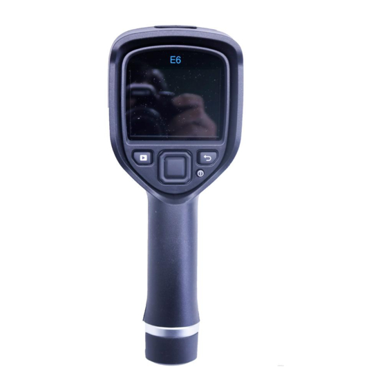
Page 38: Flir E6
The wide field of view makes them the perfect choice for building applications. Benefits: • Easy to use: The FLIR Ex series cameras are fully automatic and focus-free with an intuitive inter- face for simple measurements in thermal, visual, or MSX mode. •... - Page 39 Technical data Measurement analysis Emissivity table Emissivity table of predefined materials Reflected apparent temperature correction Automatic, based on input of reflected temperature Set-up Black and white, iron and rainbow Color palettes Set-up commands Local adaptation of units, language, date and time formats Storage of images File formats...
- Page 40 • T198531; Battery charger incl power supply • T198532; Car charger • T198534; Power supply USB-micro • T198529; Pouch FLIR Ex and ix series • T198533; USB cable Std A <-> Micro B • T198583; FLIR Tools+ (license only) #T559828; r.18043/22369; en-US...
-
Page 41: Flir E8
The wide field of view makes them the perfect choice for building applications. Benefits: • Easy to use: The FLIR Ex series cameras are fully automatic and focus-free with an intuitive inter- face for simple measurements in thermal, visual, or MSX mode. •... - Page 42 Technical data Measurement analysis Emissivity table Emissivity table of predefined materials Reflected apparent temperature correction Automatic, based on input of reflected temperature Set-up Black and white, iron and rainbow Color palettes Set-up commands Local adaptation of units, language, date and time formats Storage of images File formats...
- Page 43 • T198531; Battery charger incl power supply • T198532; Car charger • T198534; Power supply USB-micro • T198529; Pouch FLIR Ex and ix series • T198533; USB cable Std A <-> Micro B • T198583; FLIR Tools+ (license only) #T559828; r.18043/22369; en-US...
-
Page 46: Declaration Of Conformity
Declaration of conformity #T559828; r.18043/22369; en-US... -
Page 47: Cleaning The Camera
Cleaning the camera 11.1 Camera housing, cables, and other items 11.1.1 Liquids Use one of these liquids: • Warm water • A weak detergent solution 11.1.2 Equipment A soft cloth 11.1.3 Procedure Follow this procedure: 1. Soak the cloth in the liquid. 2. -
Page 48: Application Examples
Application examples 12.1 Moisture & water damage 12.1.1 General It is often possible to detect moisture and water damage in a house by using an infrared camera. This is partly because the damaged area has a different heat conduction prop- erty and partly because it has a different thermal capacity to store heat than the sur- rounding material. -
Page 49: Oxidized Socket
Application examples 12.3 Oxidized socket 12.3.1 General Depending on the type of socket and the environment in which the socket is installed, ox- ides may occur on the socket's contact surfaces. These oxides can lead to locally in- creased resistance when the socket is loaded, which can be seen in an infrared image as local temperature increase. -
Page 50: Insulation Deficiencies
Application examples 12.4 Insulation deficiencies 12.4.1 General Insulation deficiencies may result from insulation losing volume over the course of time and thereby not entirely filling the cavity in a frame wall. An infrared camera allows you to see these insulation deficiencies because they either have a different heat conduction property than sections with correctly installed insulation, and/or show the area where air is penetrating the frame of the building. -
Page 51: Draft
Application examples 12.5 Draft 12.5.1 General Draft can be found under baseboards, around door and window casings, and above ceil- ing trim. This type of draft is often possible to see with an infrared camera, as a cooler airstream cools down the surrounding surface. NOTE When you are investigating draft in a house, there should be sub-atmospheric pressure in the house. -
Page 52: About Flir Systems
R & D, non-destructive testing, process control and au- tomation, and machine vision, among many others. FLIR Systems has three manufacturing plants in the United States (Portland, OR, Bos- ton, MA, Santa Barbara, CA) and one in Sweden (Stockholm). Since 2007 there is also a manufacturing plant in Tallinn, Estonia. -
Page 53: More Than Just An Infrared Camera
10 L (2.6 US gallon) jar with liquid nitrogen. To the left of the oscilloscope the Polaroid attachment (6 kg/13 lb.) can be seen. RIGHT: FLIR One, which was launched in January 2014, is a slide- on attachment that gives iPhones thermal imaging capabilities. -
Page 54: A Few Images From Our Facilities
About FLIR Systems 13.4 A few images from our facilities Figure 13.3 LEFT: Development of system electronics; RIGHT: Testing of an FPA detector Figure 13.4 LEFT: Diamond turning machine; RIGHT: Lens polishing #T559828; r.18043/22369; en-US... -
Page 55: Glossary
Glossary absorption The amount of radiation absorbed by an object relative to the re- (absorption ceived radiation. A number between 0 and 1. factor) atmosphere The gases between the object being measured and the camera, nor- mally air. autoadjust A function making a camera perform an internal image correction. autopalette The IR image is shown with an uneven spread of colors, displaying cold objects as well as hot ones at the same time. - Page 56 Glossary image correc- A way of compensating for sensitivity differences in various parts of tion (internal or live images and also of stabilizing the camera. external) infrared Non-visible radiation, having a wavelength from about 2–13 μm. infrared isotherm A function highlighting those parts of an image that fall above, below or between one or more temperature intervals.
- Page 57 Glossary span The interval of the temperature scale, usually expressed as a signal value. spectral (radi- Amount of energy emitted from an object per unit of time, area and ant) emittance wavelength (W/m /μm) temperature A value which is the result of a subtraction between two temperature difference, or values.
-
Page 58: Thermographic Measurement Techniques
Thermographic measurement techniques 15.1 Introduction An infrared camera measures and images the emitted infrared radiation from an object. The fact that radiation is a function of object surface temperature makes it possible for the camera to calculate and display this temperature. However, the radiation measured by the camera does not only depend on the tempera- ture of the object but is also a function of the emissivity. - Page 59 Thermographic measurement techniques 15.2.1.1.1 Method 1: Direct method Follow this procedure: 1. Look for possible reflection sources, considering that the incident angle = reflection angle (a = b). Figure 15.1 1 = Reflection source 2. If the reflection source is a spot source, modify the source by obstructing it using a piece if cardboard.
- Page 60 Thermographic measurement techniques 3. Measure the radiation intensity (= apparent temperature) from the reflecting source using the following settings: • Emissivity: 1.0 • D You can measure the radiation intensity using one of the following two methods: Figure 15.3 1 = Reflection source NOTE Using a thermocouple to measure reflected apparent temperature is not recommended for two impor- tant reasons:...
-
Page 61: Reflected Apparent Temperature
50%. 15.6 Other parameters In addition, some cameras and analysis programs from FLIR Systems allow you to com- pensate for the following parameters: • Atmospheric temperature – i.e. the temperature of the atmosphere between the cam- era and the target •... - Page 62 Thermographic measurement techniques • External optics transmittance – i.e. the transmission of any external lenses or windows used in front of the camera #T559828; r.18043/22369; en-US...
-
Page 63: History Of Infrared Technology
History of infrared technology Before the year 1800, the existence of the infrared portion of the electromagnetic spec- trum wasn't even suspected. The original significance of the infrared spectrum, or simply ‘the infrared’ as it is often called, as a form of heat radiation is perhaps less obvious to- day than it was at the time of its discovery by Herschel in 1800. - Page 64 History of infrared technology When Herschel revealed his discovery, he referred to this new portion of the electromag- netic spectrum as the ‘thermometrical spectrum’. The radiation itself he sometimes re- ferred to as ‘dark heat’, or simply ‘the invisible rays’. Ironically, and contrary to popular opinion, it wasn't Herschel who originated the term ‘infrared’.
- Page 65 History of infrared technology Figure 16.4 Samuel P. Langley (1834–1906) The improvement of infrared-detector sensitivity progressed slowly. Another major break- through, made by Langley in 1880, was the invention of the bolometer. This consisted of a thin blackened strip of platinum connected in one arm of a Wheatstone bridge circuit upon which the infrared radiation was focused and to which a sensitive galvanometer re- sponded.
-
Page 66: Theory Of Thermography
Theory of thermography 17.1 Introduction The subjects of infrared radiation and the related technique of thermography are still new to many who will use an infrared camera. In this section the theory behind thermography will be given. 17.2 The electromagnetic spectrum The electromagnetic spectrum is divided arbitrarily into a number of wavelength regions, called bands, distinguished by the methods used to produce and detect the radiation. -
Page 67: Planck's Law
Such cavity radiators are commonly used as sources of radiation in tempera- ture reference standards in the laboratory for calibrating thermographic instruments, such as a FLIR Systems camera for example. If the temperature of blackbody radiation increases to more than 525°C (977°F), the source begins to be visible so that it appears to the eye no longer black. -
Page 68: Wien's Displacement Law
Theory of thermography Blackbody spectral radiant emittance at wavelength λ. λb Velocity of light = 3 × 10 Planck’s constant = 6.6 × 10 Joule sec. Boltzmann’s constant = 1.4 × 10 Joule/K. Absolute temperature (K) of a blackbody. λ Wavelength (μm). -
Page 69: Stefan-Boltzmann's Law
Theory of thermography Figure 17.5 Wilhelm Wien (1864–1928) The sun (approx. 6 000 K) emits yellow light, peaking at about 0.5 μm in the middle of the visible light spectrum. At room temperature (300 K) the peak of radiant emittance lies at 9.7 μm, in the far infra- red, while at the temperature of liquid nitrogen (77 K) the maximum of the almost insignif- icant amount of radiant emittance occurs at 38 μm, in the extreme infrared wavelengths. -
Page 70: Non-Blackbody Emitters
Theory of thermography Figure 17.7 Josef Stefan (1835–1893), and Ludwig Boltzmann (1844–1906) Using the Stefan-Boltzmann formula to calculate the power radiated by the human body, at a temperature of 300 K and an external surface area of approx. 2 m , we obtain 1 kW. - Page 71 Theory of thermography • A selective radiator, for which ε varies with wavelength According to Kirchhoff’s law, for any material the spectral emissivity and spectral absorp- tance of a body are equal at any specified temperature and wavelength. That is: From this we obtain, for an opaque material (since α...
-
Page 72: Infrared Semi-Transparent Materials
Theory of thermography Figure 17.9 Spectral emissivity of three types of radiators. 1: Spectral emissivity; 2: Wavelength; 3: Black- body; 4: Graybody; 5: Selective radiator. 17.4 Infrared semi-transparent materials Consider now a non-metallic, semi-transparent body – let us say, in the form of a thick flat plate of plastic material. -
Page 73: The Measurement Formula
The measurement formula As already mentioned, when viewing an object, the camera receives radiation not only from the object itself. It also collects radiation from the surroundings reflected via the ob- ject surface. Both these radiation contributions become attenuated to some extent by the atmosphere in the measurement path. - Page 74 U according to the same equation, and get (Equation 3): Solve Equation 3 for U (Equation 4): This is the general measurement formula used in all the FLIR Systems thermographic equipment. The voltages of the formula are: Table 18.1 Voltages Calculated camera output voltage for a blackbody of temperature i.e.
- Page 75 5 volts, the resulting curve would have been very much the same as our real curve extrapolated beyond 4.1 volts, provided the calibration algo- rithm is based on radiation physics, like the FLIR Systems algorithm. Of course there must be a limit to such extrapolations.
- Page 76 The measurement formula Figure 18.3 Relative magnitudes of radiation sources under varying measurement conditions (LW cam- era). 1: Object temperature; 2: Emittance; Obj: Object radiation; Refl: Reflected radiation; Atm: atmos- phere radiation. Fixed parameters: τ = 0.88; T = 20°C (+68°F); T = 20°C (+68°F).
-
Page 77: Emissivity Tables
Emissivity tables This section presents a compilation of emissivity data from the infrared literature and measurements made by FLIR Systems. 19.1 References 1. Mikaél A. Bramson: Infrared Radiation, A Handbook for Applications, Plenum press, N.Y. 2. William L. Wolfe, George J. Zissis: The Infrared Handbook, Office of Naval Research, Department of Navy, Washington, D.C. - Page 78 Emissivity tables Table 19.1 T: Total spectrum; SW: 2–5 µm; LW: 8–14 µm, LLW: 6.5–20 µm; 1: Material; 2: Specification; 3:Temperature in °C; 4: Spectrum; 5: Emissivity: 6:Reference (continued) Aluminum anodized, light 0.97 gray, dull Aluminum as received, plate 0.09 Aluminum as received, 0.09...
- Page 79 Emissivity tables Table 19.1 T: Total spectrum; SW: 2–5 µm; LW: 8–14 µm, LLW: 6.5–20 µm; 1: Material; 2: Specification; 3:Temperature in °C; 4: Spectrum; 5: Emissivity: 6:Reference (continued) Brass polished 0.03 Brass polished, highly 0.03 0.20 Brass rubbed with 80- grit emery Brass sheet, rolled...
- Page 80 Emissivity tables Table 19.1 T: Total spectrum; SW: 2–5 µm; LW: 8–14 µm, LLW: 6.5–20 µm; 1: Material; 2: Specification; 3:Temperature in °C; 4: Spectrum; 5: Emissivity: 6:Reference (continued) Chipboard untreated 0.90 polished 0.10 Chromium Chromium polished 500–1000 0.28–0.38 Clay fired 0.91 Cloth...
- Page 81 Emissivity tables Table 19.1 T: Total spectrum; SW: 2–5 µm; LW: 8–14 µm, LLW: 6.5–20 µm; 1: Material; 2: Specification; 3:Temperature in °C; 4: Spectrum; 5: Emissivity: 6:Reference (continued) Granite polished 0.849 Granite rough 0.879 0.95–0.97 Granite rough, 4 different samples 0.77–0.87 Granite...
- Page 82 Emissivity tables Table 19.1 T: Total spectrum; SW: 2–5 µm; LW: 8–14 µm, LLW: 6.5–20 µm; 1: Material; 2: Specification; 3:Temperature in °C; 4: Spectrum; 5: Emissivity: 6:Reference (continued) Iron and steel wrought, carefully 40–250 0.28 polished 0.64 Iron galvanized heavily oxidized Iron galvanized heavily oxidized...
- Page 83 Emissivity tables Table 19.1 T: Total spectrum; SW: 2–5 µm; LW: 8–14 µm, LLW: 6.5–20 µm; 1: Material; 2: Specification; 3:Temperature in °C; 4: Spectrum; 5: Emissivity: 6:Reference (continued) Lead red 0.93 Lead red, powder 0.93 Leather tanned 0.75–0.80 Lime 0.3–0.4 Magnesium 0.07...
- Page 84 Emissivity tables Table 19.1 T: Total spectrum; SW: 2–5 µm; LW: 8–14 µm, LLW: 6.5–20 µm; 1: Material; 2: Specification; 3:Temperature in °C; 4: Spectrum; 5: Emissivity: 6:Reference (continued) Nickel oxide 500–650 0.52–0.59 Oil, lubricating 0.025 mm film 0.27 0.46 Oil, lubricating 0.050 mm film Oil, lubricating...
- Page 85 Emissivity tables Table 19.1 T: Total spectrum; SW: 2–5 µm; LW: 8–14 µm, LLW: 6.5–20 µm; 1: Material; 2: Specification; 3:Temperature in °C; 4: Spectrum; 5: Emissivity: 6:Reference (continued) Plaster plasterboard, 0.90 untreated Plaster rough coat 0.91 Plastic glass fibre lami- 0.94 nate (printed circ.
- Page 86 Emissivity tables Table 19.1 T: Total spectrum; SW: 2–5 µm; LW: 8–14 µm, LLW: 6.5–20 µm; 1: Material; 2: Specification; 3:Temperature in °C; 4: Spectrum; 5: Emissivity: 6:Reference (continued) Soil saturated with 0.95 water Stainless steel alloy, 8% Ni, 18% 0.35 Stainless steel rolled...
- Page 87 Emissivity tables Table 19.1 T: Total spectrum; SW: 2–5 µm; LW: 8–14 µm, LLW: 6.5–20 µm; 1: Material; 2: Specification; 3:Temperature in °C; 4: Spectrum; 5: Emissivity: 6:Reference (continued) Water ice, smooth –10 0.96 Water layer >0.1 mm 0–100 0.95–0.98 thick Water snow...
- Page 88 A note on the technical production of this publication This publication was produced using XML — the eXtensible Markup Language. For more information about XML, please visit http://www.w3.org/XML/ A note on the typeface used in this publication This publication was typeset using Linotype Helvetica™ World. Helvetica™ was designed by Max Miedinger (1910–1980) LOEF (List Of Effective Files) T501027.xml;...
- Page 90 Disclaimer Specifications subject to change without further notice. Models and accessories subject to regional market considerations. License procedures may apply. Products described herein may be subject to US Export Regulations. Please refer to exportquestions@flir.com with any questions. Publ. No.: T559828...
Need help?
Do you have a question about the EX series and is the answer not in the manual?
Questions and answers