Table of Contents
Advertisement
Advertisement
Table of Contents

Related Manuals for Motorola F5208


Summary of Contents for Motorola F5208
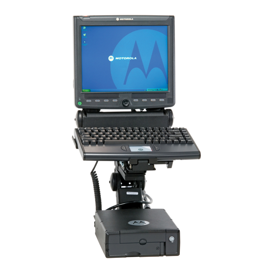
- Page 1 MW810 Mobile Workstation Model F5208, Release 1.2 User Guide MOTOA...
-
Page 3: Table Of Contents
8.4" Display Front-right Components ......19 8.4" Display - Rear Components ........22 Software Tools..............23 ExtraKey Application........... 24 Working with Two Display Units ........25 The Keyboard ............26 Keyboard Illumination............26 Illumination level ............26 © Motorola Inc., 2010 6802981C80-D April, 2010... - Page 4 Power Management Tips ..........30 Brightness Control............30 Volume Control..............30 On-Screen Display (OSD) Menu ........31 Troubleshooting ............. 32 Maintenance ............34 Smart Card Insertion Counter ......... 34 Cleaning Materials............34 Cleaning Directions ............34 Getting Assistance From Motorola......35...
-
Page 5: Computer Software Copyrights
Columbia and Canada, and is effective for MW810 Mobile Workstation shipments as of June 1, 2008. If any affected product is being purchased in response to a Motorola proposal containing a different communication products warranty, the warranty contained in that proposal will apply to such affected prod- uct. - Page 6 Three (3) Years from the date of ship- ment. Motorola, at its option, will at no charge either repair the Product (with new or reconditioned parts), replace it with the same or equivalent...
- Page 7 A) that Motorola will be notified promptly in writing by such purchaser of any notice of such claim; B) that Motorola will have sole control of the defense of such suit and all negotiations for its settlement or compromise; and...
-
Page 8: Post-Warranty Service
Product or its parts as established by Motorola. Motorola will have no liability with respect to any claim of patent infringement which is based upon the combination of the Product or its parts furnished hereunder with software, apparatus or devices not... -
Page 9: Using This Manual
MW810 Mobile Workstation, it does not provide full component descriptions. For additional information refer to the following publications: Publication Number Description MW810 Mobile Workstation Specification R3-14-2051 Sheet Motorola MW810 Mobile Workstation, 8.4” 6802984C84 Display, Installation Manual... - Page 10 Publication Number Description Motorola MW810 Mobile Workstation, User 6802981C80 Guide Motorola MW810 Mobile Workstation, Quick 6802983C72 Reference Guide (English) Motorola MW810 Mobile Workstation, Quick 6802983C71 Reference Guide (Multilingual) Motorola MW810 Mobile Workstation, Product Safety and RF Exposure for mobile workstation...
-
Page 11: Notational Conventions
For detailed product safety and RF exposure, refer to Safety and General Information leaflet, Motorola publication num- ber 6802983C01. Changes or modifications made in the CPU Box or Display, not expressly approved by Motorola, will void the user's authority to operate the equipment. Caution FCC Grant of Equipment Authorization Release 1.2... - Page 12 MW810 Mobile Frequency Range Power Workstation Radio Type FCC Grant ID Output Option No VA00507AA WLAN US 2412.0 - 2462.0 PD9533ANM 0.07 (802.11a/b/g/n) 2422.0 - 2452.0 0.13 Two connectors 5180.0 - 5240.0 0.045 5260.0 - 5320.0 0.11 5500.0 - 5700.0 0.11 5755.0 - 5795.0 0.068...
-
Page 13: Workstation Radio Configurations
Workstation Radio Configurations The MW810 Mobile Workstation can be configured for simul- taneous transmission by the following radio pairs: MW810 Mobile Workstation Radio Type Option Number. VA00024AP WLAN US VA00048AD DataTAC VA00024AP WLAN US VA00048AE DataTAC VA00024AP WLAN US VA00016AF GPRS, EGPRS, UMTS, HSDPA US VA00024AP WLAN US... -
Page 14: European Union Notification
European community. Conformity for RoHS Compliance This Motorola product is in compliance with the essential requirements and other relevant provisions of Directive 2002/ 95/EC, Restriction of the use of certain Hazardous Sub- stances (RoHS) in electrical and electronic equipment. -
Page 15: Safety Instructions
Intel® Celeron® are registered trade- marks of Intel Corporation. • The Bluetooth trademarks are owned by their proprietor and used by Motorola, Inc. under license in the U.S. and other countries. • Trimble® is a registered trademark of Trimble Naviga- tion Limited. - Page 16 • Never coil a power cord. • Always route a power cord, communication, and antenna cables to avoid damaged. Avoid damage to the MW810 Mobile Workstation by follow- ing basic safety instructions: • Your MW810 Mobile Workstation generates heat when turned on.
-
Page 17: What Is The Mw810 Mobile Workstation
The workstation is powered by a family of high-tier proces- sors with extensive memory. In addition to the basic multiple port connections option (the “No I/O Expansion board” option), the MW810 Motorola is available with three optional expansion boards: 1. The “COMM & Video I/O Expansion Board”... -
Page 18: The Cpu Box
2. The “Serial & USB I/O Expansion Board” This option supports three additional RS232 serial ports and two USB 2.0 ports. 3. The “ALPR Expansion Board” This option supports interfacing up to four PIPS P632 digital ALPR cameras, an additional display (DVI), two Ethernet ports and one USB 2.0 port. -
Page 19: The Display
MW810 Display, external 3rd party LCD, CRT or flat screen displays • Rugged mechanical design The Display The MW810 Motorola offers three optional rugged displays: • 12.1” XGA high brightness display: TFT-technology dis- play with 1200 NIT (1200 cd/m2) LCD backlighting to ensure viewing under bright light conditions. - Page 20 • Optional built-in Bluetooth radio (only 12.1“Display) to provide wireless connection to personal area peripherals such as headset, mouse, printer etc. • Three USB 2.0 ports on 12.1“ displays and two on 8.4“Display for connectivity to external USB devices...
-
Page 21: Getting The Mw810 Mobile Workstation Running
• Quick Reference Guide - 6802983C72 (English) or 6802983C71 (Multilingual) • This User Guide - 6802981C80 • Motorola MW810 Mobile Workstation, Vehicle Installa- tion Manual - 6802982C80 • RF Safety and General Information leaflet - 6802983C01 • CD with Windows 7 or Windows XP OS Inspect all the items. -
Page 22: Shutting Down The Computer
• Verify that the main power switch (MAIN SWITCH), located at the rear panel of the CPU Box, is in ON posi- tion (see Figure 2). • Press the power button on the front panel of the CPU Box or display- both buttons perform identical function. •... -
Page 23: Taking A Look At The Mw810 Mobile Workstation
Taking a Look at the MW810 Mobile Workstation CPU Box - Front Panel Components Figure 1 shows the front panel components of the CPU Box. Power Button PC/SIM Card Compartment - Do not open Removable Hard Disk Drive/Solid State Disk Drawer Figure 1. -
Page 24: Cpu Box - Rear Panel Components
CPU Box - Rear Panel Components Figure 2 and Figure 3 show the CPU Box rear panel options (for connection details, refer to MW810 Mobile Workstation, Vehicle Installation Manual p/n 6802982C80). Main Power Switch Serial 1 Display 1 Serial 2 Display 2 LAN 2 &... -
Page 25: Main Power Switch
ALPR expansion board option has two 1GB/s ports. Serial 2 Additional standard RS232 serial port. Serial 1 RS232 serial port. Connects to standard RS232 serial devices such as Motorola VRM modem, printer, mouse, etc. The con- nection requires a COTS (Commercial Off-The-Shelf) cable (not included). - Page 26 Display 2 Connection of Secondary display cable. The cable carries DVI, RGB (“COMM & Video I/O Expansion Board” only), USB and audio signals to the screen. On ALPR panel, Display 2 is DVI only. Display 1 Connection of a Primary display cable. The cable carries RGB, USB and audio signals to the screen.
- Page 27 WWAN mini-UHF AUX antenna cable for the UMTS/HSDP/HSUPA/ CDMA EV-DO radio modems. RX diversity antenna is sup- ported. Note that UMTS radio also supports two WWAN antennas. Connection to vehicle ignition switch, general purpose I/Os (digital Inputs and Outputs), 5VDC and car battery voltage outputs, vehicle speed and direction inputs from the vehicle data bus to optional dead reckoning GPS receiver.
-
Page 28: Cpu Box - Bottom Side View
CPU Box - Bottom Side View Figure 4 shows a bottom side view of the CPU Box. Cooling Fans Air Outlet Cooling Fans Air Inlet Figure 4. CPU Box - Bottom Side View The Cooling Fans Inlet and Outlet ensure proper air circulation to prevent overheating of the CPU Box. - Page 29 Remove the two screws securing the HDD/SSD Drawer to the CPU Box (see Figure 5). Pull-out the HDD/SSD Drawer from the HDD/SSD Drawer Compartment in the CPU Box. HDD/SSD Drawer Screws HDD/SSD Drawer Compartment Figure 5. CPU Box - Removable Hard Disk Drive/Solid State Disk Drawer Never try to remove the HDD/SSD Drawer before shutting down the computer and switching off Caution...
-
Page 30: 12.1" Display Front-Right Components
12.1" Display Front-right Components Figure 6 shows the front-right components of the 12.1” Dis- play. Emergency Button Touch Screen Smart Card Compartment (Optional) Contacts S m a r t C a r d USB Port Speaker Rotary Knob Eight Function Keys Power Button/ Mode LED Illuminated Labels Area Temperature LED... - Page 31 Steady Red: Display temperature is high - save your work and shut down. Resume operation only after the display cools down. Power Button/Mode LED Power Button The Power Button turns ON/OFF the workstation power (CPU Box and display). The function of the Power Button on the display and the Power Button on the CPU Box are identical.
- Page 32 Illuminated Labels Area Use this illuminated area for attaching description labels to each Function Key. Custom-made labels can be ordered through: http://israel.motorola.com/DesignCenter/LabelStrip.html Eight Function Keys The eight Function Keys facilitate specific operations. The function of each key is set via a pre-installed software Utility, called ExtraKey (See “ExtraKey Application”...
-
Page 33: 12.1" Display - Rear Components
Touch Screen The touch screen is a touch-sensitive device that allows you to communicate with the computer by controlling the location of the pointer on the screen with a finger or a Stylus and making a selection. Do not use a sharp object such as a ballpoint pen or pencil on the touch screen. - Page 34 Power Inlet 12V/24V power supply inlet from the vehicle battery system. USB Ports Three USB 2.0 ports. USB ports 1 and 2 are for temporary connection of external USB devices with up to 500mA load per port. USB port 3 is normally used to connect the MW810 Mobile Workstation keyboard.
-
Page 35: 8.4" Display Front-Right Components
8.4" Display Front-right Components Figure 8 shows the front-right components of the 8.4" Dis- play. Touch Screen Workstation Power Button USB 2.0 Port Temperature Indicator Backlight/ Illumination On/Off Key Brightness Level Control Volume Level Control Function On-Screen-Display Keys (OSD) Key Speaker Emergency Button Figure 8. - Page 36 workstation speed slows down. The workstation radios remain powered on. To resume from Suspend mode, press any control button, touch screen, keyboard or touch pad. The workstation returns to the initial state that existed prior to the Suspend mode (previous display, indications, etc.) Touch Screen SVGA, 800x600 pixels screen with analog RGB or DVI video input.
- Page 37 On-Screen-Display (OSD) The OSD menu key is used to pop-up the OSD menu and adjust the display appearance and performance. To pop-up the OSD panel on the screen, press once on the OSD key. Use the Volume level control keys to scroll between the OSD menu items.
-
Page 38: 8.4" Display - Rear Components
NOTE: Be aware, USB devices connected to the USB port should be compliant with the operating system. Otherwise the system does not operate properly. 8.4" Display - Rear Components Figure 9. shows the rear components of the 8.4” Display. (for detail installation instructions, refer to MW810 Mobile Work- station, Vehicle Installation Manual p/n 6802982C80). -
Page 39: Software Tools
Keyboard USB Port USB 2.0 port used to connect the MW810 Mobile Worksta- tion keyboard with up to 500mA current load. The Keyboard USB Port has two threaded bosses for securing the USB con- nector of the keyboard to the display. CPU-to-Display Cable Receptacle Signal cable 50 pin receptacle for connecting the display to the CPU Box. -
Page 40: Extrakey Application
ExtraKey Application The Extrakey application allows a Function Key to operate as follows: • Operate like a standard keyboard hotkey • Launch any application (like Notepad or Calculator) • Display Backlight on/off (note: There is already a dedi- cated key for this on this display) •... -
Page 41: Working With Two Display Units
Enter the full path name of the file to be opened or click the button to browse. Working with Two Display Units The MW810 Mobile Workstation is designed and equipped to support two displays (MW810 Mobile Workstation or any standard display), functioning simultaneously, using Win- dows modes of operation called Extended Mode and Twin Mode. -
Page 42: The Keyboard
display should be disabled in the Device Manager under Mouse folders -> HID mouse. • Using USB data storage devices for workstation boot A USB storage device can be used to boot the workstation. When this method is used, only one display (primary or sec- ondary) should be connected. -
Page 43: Keypad Mode
Keypad mode A 15-key numeric keypad is embedded on the typewriter keys as shown in the following example (English): Figure 11. 15-key Numeric Keypad Touch Pad The touch pad uses the standard Microsoft mouse driver. The user can adjust the pointer speed in the "Basics" dialog box of the "Mouse Properties"... -
Page 44: Mw810 Mobile Workstation Basic Operations
MW810 Mobile Workstation Basic Operations Power On The MW810 Mobile Workstation can be turned on either from the vehicle ignition switch or by pressing the power but- ton on the front panel of the CPU Box or display. The OS auto- matically loads. -
Page 45: Standby
to bring your computer out of Hibernation than out of Standby. Standby If you plan to be away from your computer, place your com- puter in Standby mode. In Standby mode the MW810 Mobile Workstation switches to a low-power mode where devices use less power. The CPU can initiate the standby manually or automatically after a period of inactivity. -
Page 46: Power Management Tips
• Pressing the Power button on the display or CPU Box (when configured). Note that the default setting of the OS disable this operation • Turning the ignition switch off (optional configuration) • Wake up event from a USB device (If capable and enabled) •... -
Page 47: On-Screen Display (Osd) Menu
On-Screen Display (OSD) Menu On-Screen Display (OSD) is a control panel, shown on a dis- play screen, that enables the adjustment of the contrast, hor- izontal and vertical positioning and other screen features. To pop-up the panel on the screen, press once on the rotary knob and scroll the knob to select the OSD menu item. -
Page 48: Troubleshooting
Troubleshooting Many problems can be solved without outside assistance by following the troubleshooting procedures provided via the on- line help or in the device documents, OS and software appli- cations. Most software applications contain troubleshooting procedures and explanation of error information. If you sus- pect a software issue, refer to the OS or application trouble- shooting guides. - Page 49 Table 2 describes MW810 Mobile Workstation error mes- sages that warn you about conditions that might prevent nor- mal operation. Table 2: MW810 Mobile Workstation Error Messages Message Do the following “Vehicle Battery is The car battery voltage is below the Low.
-
Page 50: Maintenance
Maintenance Smart Card Insertion Counter The total number of smart card insertions can be viewed by using the OSD menu, see “On-Screen Display (OSD) Menu” on page 31. Cleaning Materials Use the following materials for cleaning of plastic and glass surfaces: Film-Free glass cleaner (Unisource Worldwide, Inc) http://www.unisourcelink.com. -
Page 51: Getting Assistance From Motorola
Getting Assistance From Motorola If you are in North America and require further technical sup- port, you may call the Motorola System Support Center (SSC) at 1-800 221-7144 and choose the options for Technical Sup- port on Data products. Please be prepared to provide your unit model and serial number or Factory Order number for warranty entitlement verification purposes. - Page 52 This Page Intentionally Left Blank...
- Page 53 Numerics Front Panel Function buttons 10/100 Base-T Ethernet 8 wire GPS antenna Green ambient temperature application updates Assistance Hard Disk Drive Automatic Screen Headphones Adjustment Heater over-current high brightness hot-key battery voltage outputs Brightness 6, 28 ignition switch Illumination in Standby calibration of the screen mode CDMA...
- Page 54 PC/SIM Card Volume Power Button VRM modem Power On primary display cable Wake Up from Standby processor windows shortcut key Windows® XP Rear Panel Yellow Resetting rotary knob 18, 22 rubber plugs secondary display cable Shut Down Simultaneous use Speaker standard brightness Standby SVGA...
- Page 56 Motorola System Support Center at 1-800 221-7144 For Europe, the Middle East and Africa, call +420 533 336 123 MOTOROLA and the Stylized M Logo are registered in the U.S. Patent and Trademark Office. All other product or service names are the property of their respective owners.
Need help?
Do you have a question about the F5208 and is the answer not in the manual?
Questions and answers