Motorola MW800 Series Manual
Mobile workstation
Hide thumbs
Also See for MW800 Series:
- Owner's manual (29 pages) ,
- Owner's manual (33 pages) ,
- Vehicle installation manual (56 pages)
Table of Contents
Advertisement
Quick Links
Advertisement
Table of Contents

Related Manuals for Motorola MW800 Series


Summary of Contents for Motorola MW800 Series
- Page 1 Mobile Workstation MW800 Series Models F5207A, F5217A 6802976C65-O...
- Page 2 COPYRIGHT Copyright © 2004-2005 Motorola Inc. All rights reserved. No part of this manual may be transmitted, stored in a retrieval system, or translated into any language or computer language, in any form or by any means, without the prior written permission of Motorola Inc.
-
Page 3: Table Of Contents
Tips for F5217A Installation........................29 Speed car pulse connection ......................... 29 Backward/ Forward connection ......................29 Section 6: Maintenance........................30 Cleaning the Keyboard ..........................30 Cleaning the Display..........................30 Section 7: Getting Assistance from Motorola................... 31 Appendix A: Safety Instructions....................... 32... - Page 4 Appendix B: Warranty Information....................34 Appendix C: FCC Information ......................37 Appendix D: Environmental Specifications ..................38 Appendix E: OSD Specifications ..................... 39 On Screen Display (OSD) Calibration..................... 39 OSD Sub-Group Icons ..........................39 Warning Icons............................42 Appendix F: Troubleshooting ......................43 Appendix G: Acronyms and Abbreviations..................
-
Page 5: Using This Manual
MW800 User’s Guide Using this Manual Before using this manual and products it describes, be sure to read the Safety instructions in Appendix A, the Warranty information in Appendix B and the FCC information in Appendix C. Who Should Use this Manual This manual is intended for staff that operates the Mobile Workstation 800 in vehicles. -
Page 6: Related Manuals
• Section 4 provides a description of basic operations • Section 5 describes installation tips • Section 6 describes storage and maintenance rules • Section 7 describes how to get assistance from Motorola The Appendixes contain: • Appendix A: Safety instructions •... -
Page 7: Conventions Used In This Manual
Used to indicate keyboard keys or application buttons. Program -> Used to designate the location and name of a menu Motorola -> function. For example, Program -> Motorola -> MW800 MW800 CPU-> CPU-> CPU Manager launch CPU Manager program. CPU Manager... -
Page 8: Getting Started
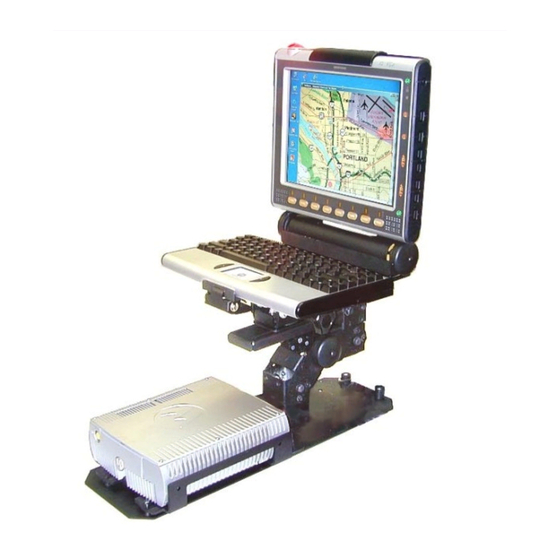
Getting Started What is the MW800 Mobile Workstation? The Motorola Mobile Workstation 800 series is Motorola's highest-performing and most rugged data communication and computing solution. It is specifically designed for the harsh conditions of the mobile environment-areas not suitable for conventional laptop or desktop computers. -
Page 9: Installation And Connecting To Car Battery
MW800 User’s Guide • This User’s Guide Inspect all the items. If any item is missing or damaged, notify your Motorola Customer Service representative immediately. Installation and Connecting to Car Battery Please, refer to the Mobile Workstation 800 Installation Manual and strictly follow the installation procedure. -
Page 10: Taking A Look At The Mw800
Section 2: Taking a Look at the MW800 This chapter identifies the external components of each part of the MW800 and provides a brief functional description. CPU Box The front side of the CPU box allows user interface with Power button, PC and radio SIM cards.. -
Page 11: Rear-Side Components
For connecting a Firewire® device (IEEE1394) such as a digital camera, scanner, etc. NOTE: not applicable for model F5217A. For connecting the power cord from the vehicle’s battery. CAUTION: Use a standard Motorola power cable with a 15-Amp fuse. WWAN For connecting mini-UHF radio modem antenna for GPRS,... - Page 12 NOTE: not applicable for model F5217A. For connecting the LAN cable. Includes a Link and Active indicators. Serial 1 For connecting a serial device such as Motorola’s VRM modems, printer, mouse, etc. The connection requires a COTS (Commercial Off-The-Shelf) cable (not supplied). Serial 2 Additional serial connection in model F5217A only.
-
Page 13: Bottom-Side Components
MW800 User’s Guide Bottom-Side Components The Hard Disk Compartment is located at the bottom of the CPU box. The Hard Disk Compartment contains the removable hard disk drive. Figure 4. Bottom View – Hard Disk Drive Top View Ventilation Openings Figure 5. -
Page 14: Display
Display This section identifies external display components and briefly describes their function. Front View Hand Grip Emergency Button Control Buttons Left Speaker Right Speaker Function Buttons Figure 6. 12.1” Display Components Control Buttons Emergency Button Function Buttons Speaker Figure 7. 8.4’’ Display Components... -
Page 15: Bottom-Side Components
MW800 User’s Guide Speakers The speakers (two in 12.1”, one in 8.4” display) are used for audio and alert signaling. NOTE: Adjust speaker volume with the Volume Up/Down buttons or with the Volume Control program. The Volume Control program can be found on the Windows task bar (speaker icon). -
Page 16: Right-Side Components
For connecting the power cord from the vehicle battery. Use a standard Motorola power cable with a 15-Amp fuse. CPU Cable Connects the display to the CPU box. Each port connects a USB 1.1 device such a keyboard, mouse, etc. -
Page 17: Display Indicators
MW800 User’s Guide power-saving mode, turns off the display backlight and slows down the processor speed. The workstation radios remain powered on. Backlight Button Turns the LCD backlight ON and OFF; provides five levels of illumination to the display buttons and indicators. Brightness Up/Down Buttons Increases (the upper button) or decreases (the lower button) -
Page 18: Keyboard
Communication Off: Normal operation Steady blue: CPU box to display USB power problem, or display in programming mode. Check cable connection Steady yellow: CPU box fails to communicate with the display. Steady purple: CPU box to display USB power and communication problem. -
Page 19: Tips
MW800 User’s Guide Tips • To change illumination level of the keyboard backlight, press the Fn key and tap on the left or right arrow keys. The level of illumination will change repeatedly from off to maximum in seven steps. The keyboard incorporates a power saving feature that automatically turns off •... -
Page 20: Specifications
Section 3: Specifications Specifications Size • CPU: Width: 7.75” (19.7 cm); Depth: 9.45” (24.0 cm); Height: 2.74” (6.95 cm) • 12.1” Display: Width: 12.2” (31 cm); Depth: 10.6” (26.9 cm); Height: 2.2” (5.6 cm) • 8.4” Display: Width: 9.1” (23.1 cm); Depth: 7.1” (18.1 cm); Height: 1.69” (4.3 cm) •... -
Page 21: Features
MW800 User’s Guide Features Operating System: • Windows XP Pro or Windows 2000. Basic Processor (other options available): • Intel Pentium M (Centrino) #715 1.5 GHz processor. Memory (other options available): • Double data rate (DDR) synchronous expandable dynamic random access memory (DRAM) 256 MB. - Page 22 • SIM card slot • RJ45 Ethernet connector • RS-232 DB9 connector for F5207A, 2 RS-232 DB9 connectors for F5217A • Microphone jack • Stereo headphone jack • Firewire (IEEE1394) port for F5207A • Composite video input (PAL or NTSC) •...
-
Page 23: Basic Operations
MW800 User’s Guide Section 4: Basic Operations This chapter provides basic information about the use of the MW800. It describes the following operations: • Power On • Power Off • Reset • Access to PC and SIM cards • Volume Control •... -
Page 24: Discharged Vehicle Battery
NOTE: Your device performance might be slightly degraded (both boot up time and sustained operations) during extreme temperature conditions. Normal operation will resume when the ambient temperature returns to the operating range. Discharged Vehicle Battery If the power source is a standard 13.8V car battery, the device will normally power up when the voltage level exceeds 10.3 VDC. -
Page 25: Extreme Shut Down
MW800 User’s Guide CAUTION: If the system does not respond, you can turn the device off by pressing and holding the power button for 6 seconds or more. Be aware, this hardware power off may damage your hard disk. Extreme Shut Down Some extreme events may cause your device to power off. -
Page 26: Personal Card
function of the operating system, reset your device. Be aware that resetting will cause unsaved data to be lost. To reset the device, press the <Ctrl+Alt+Del> keys, and select the Shut Down option from the Windows shut down screen. CAUTION: If the system does not respond, you can turn the device off by pressing and holding the power button for 6 seconds or more. -
Page 27: Volume Control
MW800 User’s Guide To remove a SIM Card from the slot: • Pull the door latch and open the PC slot door. • Push the button and pullout the card from the slot. CAUTION: Inserting/removing SIM card when MW800 is running can corrupt SIM card information. -
Page 28: Installation Tips
Section 5: Installation Tips Connection of the MW 800 CPU Box to a Third party Display An optional cable adapter (FKN8144) enables you to interface the MW 800 CPU box with most 3 party displays. The cable adapter connects to the standard CPU- Display signal cable. -
Page 29: Tips For F5217A Installation
MW800 User’s Guide Tips for F5217A Installation • Use the AUX 26 pin cable Motorola p/n 3087563V93 for interface to the vehicle to access to vehicle speed and direction outputs. Reading the vehicle speed signals • Connect the “+” terminal of the vehicle speed signals to the AUX port pin1 (black wire). -
Page 30: Maintenance
Section 6: Maintenance Cleaning the Keyboard • Spray some ethyl or rubbing (isopropyl) alcohol on a dry soft cloth. • Wipe the keyboard surface with the cloth. • Let the keyboard dry for few minutes. If the keyboard is very dirty and sticky as a result of a liquid spill, contact a service technician. -
Page 31: Getting Assistance From Motorola
MW800 User’s Guide Section 7: Getting Assistance from Motorola For your convenience, the Motorola website provides up-to-date information about the MW800. The URL address for the MW800 home page is http://www.motorola.com. This site includes general information about the device, as well as answers to questions regarding operational issues with the MW800. -
Page 32: Appendix A: Safety Instructions
Appendix A: Safety Instructions WARNING: Reduce the risk of fire or electric shock by following basic safety instructions: • Do not use your device during electrical storms. • Do not connect or disconnect cables while you device is turned on. •... - Page 33 MW800 User’s Guide Hard drive performance and lifetime could be shortened if your device is not used for long periods of time. Do not leave the device unused for more than 3 months. CAUTION: Your device automatically shuts down when the internal temperature exceeds the high limit of the valid range.
-
Page 34: Appendix B: Warranty Information
One (1) Year from the date of shipment. Motorola, at its option, will at no charge either repair the Product (with new or reconditioned parts), replace it with the same or equivalent Product (using new or reconditioned Product), or refund the purchase price of the Product during the warranty period provided purchaser notifies Motorola according to the terms of this warranty. - Page 35 State of Illinois and the Province of Ontario, respectively. VI. PATENT AND SOFTWARE PROVISIONS: Motorola will defend, at its own expense, any suit brought against the end user purchaser to the extent that it is based on a claim that the Product or its parts infringe a United...
- Page 36 A) that Motorola will be notified promptly in writing by such purchaser of any notice of such claim; B) that Motorola will have sole control of the defense of such suit and all negotiations for its settlement or compromise; and...
-
Page 37: Appendix C: Fcc Information
MW800 User’s Guide Appendix C: FCC Information CAUTION: Changes or modifications made in the CPU box or Display, not expressly approved by Motorola, will void the user's authority to operate the equipment EPS – 48759 – O FCC INTERFERENCE WARNING... -
Page 38: Appendix D: Environmental Specifications
Appendix D: Environmental Specifications • Storage temperature: -40° to 158° F (-40° to +70° C) • Operating temperature: -22° to 158° F (-30° to +70° C) • Humidity: 90 to 95% Relative humidity at 50° C for 8 hours • Shock: 20g peak 1/2 sine wave @ 11ms, 30 impacts •... -
Page 39: Appendix E: Osd Specifications
MW800 User’s Guide Appendix E: OSD Specifications On Screen Display (OSD) Calibration The MW800 incorporates a transmissive color Thin Film Transistor (TFT) LCD, which provides the best possible readability in lighting conditions typically found in the vehicle environment. The MW 800 comes configured with color palette settings optimized for operation in the vehicle. -
Page 40: Figure 16. Osd Sub-Group Icons
Figure 16. OSD Sub-Group Icons. - Page 41 MW800 User’s Guide Reset options: Factory reset Reset all settings to a factory default and re-synchronize on input signal. Accept/Reject menu will appear if this option chosen. Reset Color Reset RGB settings. Reset Image Resynchronize on input signal. Reset OSD Reset OSD position, timeout and lock settings.
-
Page 42: Warning Icons
Warning Icons Display signal cable not connected Appears every time the display fails to recognize the input signal. May appear during reset process, suspend/resume sequence or when the display cable was disconnected. Figure 17. Connection Warning Mode Error Input mode is not supported. Please, change input resolution and/or refresh rate. Figure 18. -
Page 43: Appendix F: Troubleshooting
MW800 User’s Guide Appendix F: Troubleshooting Many problems can be solved without outside assistance by following the troubleshooting procedures provided via the online help or in the device documents, operating system and software applications. Most software applications contain troubleshooting procedures and explanation of error information. If you suspect a software issue, refer to the operating system or application troubleshooting guides. -
Page 44: Table 2. Indications About Failure Condition
Table 2. Indications about failure condition Indication What’s the problem Power LED is off Check the plug and the power cord. Power LED is steady yellow Vehicle battery is low (9.4 to 10.3 VDC) during workstation power up. Temperature LED blinks red Display temperature is extremely high during power on Temperature LED blinks yellow... -
Page 45: Appendix G: Acronyms And Abbreviations
MW800 User’s Guide Appendix G: Acronyms and Abbreviations The following acronyms and abbreviations are used in this document: BIOS Basic Input Output System Compact Disk CDMA Code Division Multiple Access CMOS Configuration Memory Operating System Communication COTS Commercial Of-The-Shelf Central Processor Unit Cathode Ray Tube Double Data Rate DRAM... - Page 46 Thin Film Transistor TSIP Trimble Standard Interface Protocol Transistor-Transistor Logic Ultra High Frequency Underwriters Laboratories Universal Serial Bus Videocassette Recorder Volts Direct Current WWAN Wireless Wide Area Network WLAN Wireless Local Area Network eXtended Video Graphics Array...
Need help?
Do you have a question about the MW800 Series and is the answer not in the manual?
Questions and answers