Mitsubishi Electric FR-S500 Series Instruction Manual
Transistorized inverter
Hide thumbs
Also See for FR-S500 Series:
- Instruction manual (77 pages) ,
- Instruction manual (222 pages) ,
- Instruction manual (85 pages)
Table of Contents
Advertisement
TRANSISTORIZED INVERTER
FR-S
500
INSTRUCTION MANUAL (BASIC)
FR-S520E-0.1K to 3.7K-NA
FR-S540E-0.4K to 3.7K-NA
FR-S510WE-0.1K to 0.75K-NA
Thank you for choosing this Mitsubishi transistorized inverter.
If this is the first time for you to use the FR-S500 series, please read through this instruction manual (basic)
carefully and use the inverter safely.
If you are going to use the inverter for higher-level applications, the FR-S500 instruction manual (detailed)
[IB(NA)-0600209ENG] is separately available from where you purchased the inverter or a Mitsubishi sales
representative.
1
CONNECTION OF PERIPHERAL DEVICES ............................................. 2
1.1 Basic configuration ...................................................................................... 2
2
INSTALLATION METHOD.......................................................................... 5
2.1 Installation of the inverter............................................................................. 5
3
SPECIFICATIONS OF WIRING AND TERMINALS ................................... 6
3.1 Terminal connection diagram ...................................................................... 6
3.2 Main circuit................................................................................................... 7
3.3 Control circuit............................................................................................. 11
4
DRIVE THE MOTOR ................................................................................. 18
4.1 Step of operation ....................................................................................... 18
4.2 Run and operation ..................................................................................... 19
mode)........................................................................................................ 21
4.5 Clearing the parameters ............................................................................ 36
4.6 Monitoring the output current..................................................................... 37
5
POTENTIOMETER AND INDICATOR...................................................... 38
(bias and gain of frequency setting voltage (current)) .............................. 39
5.2 Adjustment (calibration) of the frequency meter (indicator) ....................... 43
6
FUNCTION LIST ....................................................................................... 44
6.1 Basic function parameter list...................................................................... 44
6.2 Explanation of the basic function parameters............................................ 45
6.3 Setting the parameters .............................................................................. 47
6.4 Display the extended function parameter .................................................. 48
6.5 Extended function parameter list ............................................................... 49
7
ERRORS AND PROTECTIVE FUNCTIONS ............................................ 62
7.1 About errors (definitions) ........................................................................... 62
7.2 Checking of the alarm history .................................................................... 65
(only when FR-PU04 is used).................................................................. 66
7.4 Correspondence between digital and actual characters............................ 66
7.5 Resetting the inverter................................................................................. 66
7.6 Troubleshooting ......................................................................................... 67
7.7 Precautions for maintenance and inspection............................................. 70
8
SPECIFICATIONS .................................................................................... 76
8.1 Ratings....................................................................................................... 76
8.2 Common specifications.............................................................................. 79
9
OUTLINE DRAWINGS.............................................................................. 81
Appendix 2 Instructions for UL and cUL.............................................. 86
1
2
3
4
5
6
7
8
9
Advertisement
Table of Contents

Related Manuals for Mitsubishi Electric FR-S500 Series


Summary of Contents for Mitsubishi Electric FR-S500 Series
-
Page 1: Table Of Contents
TRANSISTORIZED INVERTER FR-S INSTRUCTION MANUAL (BASIC) FR-S520E-0.1K to 3.7K-NA FR-S540E-0.4K to 3.7K-NA FR-S510WE-0.1K to 0.75K-NA Thank you for choosing this Mitsubishi transistorized inverter. If this is the first time for you to use the FR-S500 series, please read through this instruction manual (basic) carefully and use the inverter safely. - Page 2 This instruction manual (basic) provides handling information and precautions for use of the equipment. Please forward this instruction manual (basic) to the end user. This section is specifically about safety matters Do not attempt to install, operate, maintain or inspect the inverter until you have read through this instruction manual (basic) and appended documents carefully and can use the equipment correctly.
- Page 3 2. Fire Prevention CAUTION Install the inverter on an incombustible wall without holes, etc. Installing the inverter directly on or near a combustible surface could lead to a fire. If the inverter has become faulty, switch off the inverter power. A continuous flow of large current could cause a fire.
- Page 4 (2) Wiring CAUTION Do not fit capacitive equipment such as power factor correction capacitor, radio noise filter (option FR-BIF(-H)) or surge suppressor to the output of the inverter. The connection orientation of the output cables U, V, W to the motor will affect the direction of rotation of the motor.
- Page 5 CAUTION The electronic thermal relay function does not guarantee protection of the motor from overheating. Do not use a magnetic contactor on the inverter input for frequent starting/stopping of the inverter. Use a noise filter to reduce the effect of electromagnetic interference. Otherwise nearby electronic equipment may be affected.
-
Page 6: Contents
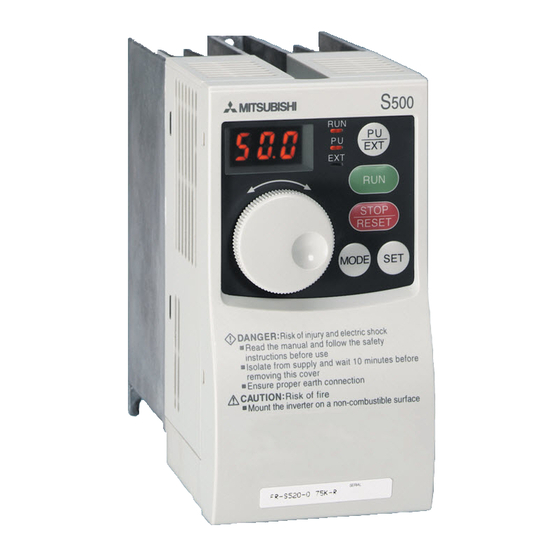
Product Checking and Parts Identification Unpack the inverter and check the capacity plate on the front cover and the rating plate on the inverter side face to ensure that the product agrees with your order and the inverter is intact. Parts and name plate Rating plate FR-S520E-0.1K-NA... -
Page 7: Connection Of Peripheral Devices
Basic configuration CONNECTION OF PERIPHERAL DEVICES 1.1 Basic configuration Power supply Use within the permissible power supply specifications of the inverter. (Refer to page 76.) No-fuse breaker or earth leakage circuit breaker The breaker must be selected carefully since an in- rush current flows in the inverter at power on. - Page 8 Basic configuration Selection of peripheral devices (selection changes with the power input specifications of the inverter) 1) Three-phase 200V power input No-fuse Breaker Magnetic Motor (NFB *1, 4) or Contactor AC Reactor DC Reactor Output Applied Inverter Earth Leakage (MC) FR-HAL- FR-HEL- Type...
- Page 9 Basic configuration 3) Single-phase 100V power input No-fuse Breaker Magnetic Motor (NFB *1, 4) or AC Reactor(*3) DC Reactor (*5) Contactor Output Applied Inverter Earth Leakage (MC) FR-HAL- FR-HEL- Type Circuit Breaker (Refer to FR-BAL- FR-BEL- (HP)) page 17) (ELB) (*2, 4) ...
-
Page 10: Installation Method
Installation of the inverter INSTALLATION METHOD 2.1 Installation of the inverter Enclosure surface mounting Encasing multiple inverters Fix the front cover and wiring cover after removing them. Vertical When containing two or more inverters, install them in parallel Leave enough clearances and provide cooling measures. -
Page 11: Specifications Of Wiring And Terminals
Terminal connection diagram SPECIFICATIONS OF WIRING AND TERMINALS 3.1 Terminal connection diagram Three-phase 200V power input Three-phase 400V power input Inverter NFB MC Motor Three-phase AC R/L1 S/L2 power supply T/L3 Ground External transistor common 24VDC power supply DC reactor Contact input common (source) (FR-HEL/BEL: Option) Take care not to short... -
Page 12: Main Circuit
Main circuit Single-phase 100V power input Motor Power supply Ground REMARKS • To ensure safety, connect the power input to the inverter via a magnetic contactor and earth leakage circuit breaker or no-fuse breaker, and use the magnetic contactor to switch power on-off. •... -
Page 13: Terminal Block Layout
Main circuit 3.2.2 Terminal block layout 1) Three-phase 200V power input • FR-S520E-0.1K, 0.2K-NA • FR-S520E-1.5K, 2.2K, 3.7K-NA Jumper Jumper R/L1 S/L2 T/L3 R/L1 S/L2 T/L3 Power supply Motor Motor Power supply • FR-S520E-0.4K, 0.75K-NA Jumper R/L1 S/L2 T/L3 Motor Power supply <When single-phase power is applied to three-phase power input inverter (FR-S520E-0.1K to 3.7K-NA only)>... - Page 14 Main circuit 2) Three-phase 400V power input • FR-S540E-0.4K, 0.75K, 1.5K, 2.2K, 3.7K-NA Jumper R/L1 S/L2 T/L3 Power supply Motor 3) Single-phase 100V power input • FR-S510WE-0.1K, 0.2K, 0.4K-NA • FR-S510WE-0.75K-NA R/L1 S/L2 R/L1 S/L2 Motor Power supply Motor Power supply CAUTION •...
- Page 15 Main circuit 3.2.3 Cables, wiring length, and crimping terminals The following table indicates a selection example for the wiring length of 20m (65.62 feet). 1) Three-phase 200V power input Cable Size Ter- Tight- Crimping HIV cable PVC cable minal ening Applied Inverter Terminal Screw...
-
Page 16: Control Circuit
Control circuit 3.3 Control circuit 3.3.1 Explanation of control circuit terminals Symbol Terminal Name Definition When the STF and STR Turn on the STF signal to Forward rotation signals are turned on start forward rotation and start simultaneously, the stop turn it off to stop. - Page 17 Control circuit Symbol Terminal Name Definition Changeover contact output indicates that the inverter protective function has activated and the output stopped. Alarm output 230VAC 0.3A, 30VDC 0.3A. Alarm: discontinuity across B-C (continuity The function of the across A-C), Normal: continuity across terminals changes B-C (discontinuity across A-C).(*5) according to the...
- Page 18 Control circuit 3.3.2 Arrangement and wiring of control circuit terminals SE RUN 10 SD STF STR RM RH Loosen the terminal screw and insert the cable into the Cable stripping size terminal. Screw size: M3 (A, B, C terminals), M2 (other than the above) Tightening torque: 0.5N•m to 0.6N•m (A, B, C terminals) Wire the stripped cable after 0.22N•m to 0.25N•m (other than the...
- Page 19 Control circuit 3.3.3 Connection to RS-485 connector (1) When connecting the parameter unit Use the optional FR-CB2 . When the parameter unit (FR-PU04) is used, operation from the operation panel is not accepted. ( is valid) STOP RESET (2) RS-485 communication Using the RS-485 connector, you can perform communication operation from a personal computer etc.
-
Page 20: Changing The Control Logic
Control circuit 3.3.4 Changing the control logic The input signals are set to sink logic. To change the control logic, the jumper connector under the setting dial must be moved to the other position. Change the jumper connector position using tweezers, a pair of long-nose pliers etc. - Page 21 Control circuit 2) Source logic type • In this logic, a signal switches on when a current flows into the corresponding signal input terminal. Terminal PC is common to the contact input signals. For the open collector output signals, terminal SE is a positive external power supply terminal. Inverter AX80 Power...
- Page 22 Control circuit 3.3.5 Power-off and magnetic contactor (MC) (1) Inverter input side magnetic contactor (MC) On the inverter's input side, it is recommended to provide an MC for the following purposes. (Refer to page 3 for selection) 1) To release the inverter from the power supply when the inverter protective function is activated or the drive becomes faulty (e.g.
-
Page 23: Drive The Motor
Step of operation DRIVE THE MOTOR 4.1 Step of operation The inverter needs frequency command and start command. Turning the start command on start the motor rotating and the motor speed is determined by the frequency command. Refer to the flow chart below to perform setting. Step of operation Step of operation of op... -
Page 24: Run And Operation
Run and operation 4.2 Run and operation 4.2.1 Parts of the operation panel The operation panel cannot be removed from the inverter. RUN indication PU/EXT Key Used to switch between the Turns on/flickers* to indicate operation. PU and external operation mode.When using the external PU indication ** operation mode (operation... -
Page 25: Basic Operation
Run and operation 4.2.2 Basic operation The following explains the outline of operation. (factory setting) <Basic operation> (factory setting) At powering on Monitor/frequency setting [Operation panel is used for operation] Frequency setting has been written and completed!! Return Press Turn the Press Press and frequen cy flickers. -
Page 26: Operation By The Start Command From The Operation Panel (Pu Operation Mode)
Operation by the start command from the operation panel (PU operation mode) 4.3 Operation by the start command from the opera- tion panel (PU operation mode) 4.3.1 Setting the frequency to perform operation (example: performing operation at 30Hz) POINT •Set "0" (setting dial frequency setting mode) in Pr. 53 "frequency setting operation selection". - Page 27 Operation by the start command from the operation panel (PU operation mode) 4.3.2 Using the setting dial like a potentiometer to perform operation POINT •Set "1" (extended function parameter valid) in Pr. 30 "extended function display selection". •Set "1" (setting dial potentiometer mode) in Pr. 53 "frequency setting operation selection".
- Page 28 Operation by the start command from the operation panel (PU operation mode) 4.3.3 Use switchs to give a start command and a frequency command (multi-speed setting) POINT •Use to give a start command. •Pr. 79 "Operation mode selection" must be set to "4" (external/PU combined operation mode 2) •The factory setting of the terminal RH, RM, RL, are 60Hz, 30Hz, and 10Hz.
- Page 29 Operation by the start command from the operation panel (PU operation mode) Mode/monitor check Press twice to choose the MODE MODE monitor/frequency monitor. Press the start switch Flickering RUN flickers. When the frequency command is not given, it flickers. Low speed Turn on the low speed switch (RL).
- Page 30 Operation by the start command from the operation panel (PU operation mode) 4.3.4 Perform frequency setting by analog (voltage input) POINT [Connection diagram] Inverter •Use to give a start com- Three-phase mand. Motor AC power supply •Pr. 79 "Operation mode selection" must be set to "4"...
- Page 31 Operation by the start command from the operation panel (PU operation mode) 4.3.5 Perform frequency setting by analog (current input) POINT •Assign the AU signal to any of the terminal RH, RM, RL, or STR and turn on the AU signal. •Pr.
- Page 32 Operation by the start command from the operation panel (PU operation mode) [Perform frequency setting by analog (current input) ] Operation Display Change the Pr.79 setting to " ". (Refer to page 23 for change of the setting.) Flicker Parameter setting complete!! Mode/monitor check MODE Press...
-
Page 33: Operation By The Start Command Of The Terminal Block (External Operation)28
Operation by the start command of the terminal block (external operation) 4.4 Operation by the start command of the terminal block (external operation) 4.4.1 Use the set frequency set by the operation panel (Pr.79=3) POINT • Switch terminal STF(STR)-SD on to give a start command. •... - Page 34 Operation by the start command of the terminal block (external operation) Mode/monitor check MODE MODE Press twice to choose the monitor/frequency monitor. Forward rotation Reverse Turn the start switch (STF or rotation STR) on. The motor runs at the frequency set in the set frequency mode of the operation panel.
- Page 35 Operation by the start command of the terminal block (external operation) 4.4.2 Use switches to give a start command and a frequency command (multi-speed setting) POINT •Start command by terminal STF (STR)-SD •Frequency command by terminal RH, RM, RL-SD. •[EXT] must be lit. (When [PU] is lit, switch it to [EXT] with •The initial values of the terminals RH, RM, RL, are 60Hz, 30Hz, and 10Hz.
- Page 36 Operation by the start command of the terminal block (external operation) Turn to change it to the seting value of " ". (50.0Hz) Press to set. Flicker Parameter setting complete!! Mode/monitor check MODE Press twice to choose the MODE monitor/frequency monitor. High speed Turn on the high speed Middle speed...
- Page 37 Operation by the start command of the terminal block (external operation) 4.4.3 Perform frequency setting by analog (voltage input) [Connection diagram] (The inverter supplies 5V of power to frequency setting potentiometer. (Termianl 10)) Inverter Three-phase Motor AC power supply Forward rotation start Reverse rotation start...
- Page 38 Operation by the start command of the terminal block (external operation) REMARKS To make a reverse rotation start, Pr. 63 "STR terminal function selection" must be set to "---". The motor will not rotate ... Why? Check that [EXT] is lit. [EXT] is valid when Pr.
- Page 39 Operation by the start command of the terminal block (external operation) 4.4.4 Perform frequency setting by analog (current input) POINT • Switch terminal STF(STR)-SD on to give a start command. Assign the AU signal to any of the terminal RH, RM, RL, or STR and turn on the •...
- Page 40 Operation by the start command of the terminal block (external operation) Deceleration Output of the Flickers Perform 4mA input. adjustment meter The frequency value on the indication (4 to 20mADC) decreases according to Pr. 8 "Deceleration time" until 0.0Hz is displayed and RUN of the operation status indication flickers.
-
Page 41: Clearing The Parameters
Clearing the parameters 4.5 Clearing the parameters POINT •The clear parameter CLr is an extended parameter. Set "1" in Pr. 30 and turn the dial to show it. (Refer to page 48.) •The parameters can be cleared by setting "1" in CLr "parameter clear". Operation Display Confirm the RUN indication and... -
Page 42: Monitoring The Output Current
Monitoring the output current 4.6 Monitoring the output current POINT The output current appears while the is pressed in the monitor mode. Operation Display Press the to choose the output MODE frequency monitor mode. Independently of whether the inverter (1.0A) is running in any operation mode or at a stop, the output current appears Hold down... -
Page 43: Adjustment Of The Frequency Setting
ADJUSTMENT OF THE FREQUENCY SETTING POTENTIOMETER AND INDICATOR Related parameters Parameter Name Setting Range Factory Setting Frequency setting voltage gain frequency 1 to 120Hz 60Hz Frequency setting current gain frequency 1 to 120Hz 60Hz Frequency setting voltage bias frequency 0 to 60Hz Frequency setting voltage bias 0 to 300% 0% *1... -
Page 44: Changing The Output Frequency Setting Of The Frequency Setting Potentiometer (Bias And Gain Of Frequency Setting Voltage (Current))
Changing the output frequency setting of the frequency setting potentiometer (bias and gain of frequency setting voltage (current)) 5.1 Changing the output frequency setting of the frequency setting potentiometer (bias and gain of frequency setting voltage (current)) POINT Pr. 38, Pr. 39 and calibration parameters "C1 to C7" can be made to be read by setting "1"... - Page 45 Changing the output frequency setting of the frequency setting potentiometer (bias and gain of frequency setting voltage (current)) Changing example When you want to use the 0 to 5VDC input frequency setting potentiometer to change the 5V-time frequency from 60Hz (factory setting) to 50Hz. POINT •Pr.
- Page 46 Changing the output frequency setting of the frequency setting potentiometer (bias and gain of frequency setting voltage (current)) Changing example When you want to use the 4 to 20ADC input frequency setting potentiometer to change the 20mA-time frequency from 60Hz (factory setting) to 50Hz. POINT •Pr.
- Page 47 Changing the output frequency setting of the frequency setting potentiometer (bias and gain of frequency setting voltage (current)) Changing example Changing the calibration parameter C4 "frequency setting voltage gain" POINT The calibration parameter C4 is an extended function parameter. Pr. 30 must be set to "1".
-
Page 48: Adjustment (Calibration) Of The Frequency Meter (Indicator)
Adjustment (calibration) of the frequency meter (indicator) 5.2 Adjustment (calibration) of the frequency meter (indicator) Changing example Deflecting the meter (analog indicator) to full-scale (5V) at the preset frequency of 60Hz. (Refer to page 21 for frequency setting.) POINT • The calibration parameters "C1"... -
Page 49: Function List
Basic function parameter list FUNCTION LIST 6.1 Basic function parameter list Minimum Param Setting Factory Customer Name Indication Setting eter Range Setting Setting Increments Torque boost 0 to 15% 0.1% 6%/5%/4% * Maximum 0 to 120Hz 0.1Hz 60Hz frequency Minimum 0 to 120Hz 0.1Hz frequency... -
Page 50: Explanation Of The Basic Function Parameters
Explanation of the basic function parameters 6.2 Explanation of the basic function parameters For details, refer to the separately available instruction manual (detailed). Pr. 0 "torque boost" Pr. 1 "maximum frequency", Pr. 2 "minimum frequency" Allows the motor torque in the low speed range to be adjusted according to the load. - Page 51 Explanation of the basic function parameters Pr. 7 "acceleration time", Pr. 9 "electronic thermal O/L relay" Pr. 8 "deceleration time" You can set a current value for protection of As the acceleration time, set the time taken to the motor from overheat. Normally, set the reach the acceleration/deceleration reference rated motor current at 50Hz as it is.
-
Page 52: Error Display
Setting the parameters 6.3 Setting the parameters 6.3.1 Example: Changing the Pr. 7 setting from "5s" to "10s" (For parameter details, refer to the instruction manual (detailed).) Display Operation Confirm the RUN indication and operation mode indication. The inverter must be at a stop. The inverter must be in the PU The parameter operation mode. -
Page 53: Display The Extended Function Parameter
Display the extended function parameter 6.4 Display the extended function parameter (The extended parameters are made valid by setting "1" in Pr. 30 "extended function display selection". ) Operation Display Confirm the RUN indication and operation mode indication. The inverter must be at a stop. -
Page 54: Extended Function Parameter List
Extended function parameter list 6.5 Extended function parameter list Setting "1" in Pr. 30 "extended function display selection" makes the extended function parameters valid. (Refer to the separately available instruction manual (detailed).) Parameter Factory Name Description Setting Indication For parameters 0 to 9, refer to the basic function parameters. (page 45) DC injection brake Set the timing of switching to DC injection operation frequency... - Page 55 Extended function parameter list Parameter Factory Name Description Indication Setting Indicates the magnitude of the output voltage at the base frequency (Pr.3) 888: 95% of power supply voltage Base frequency (1.9 times greater than the power supply - - - voltage for the 100V class) voltage - - -: Same as power supply voltage...
- Page 56 Extended function parameter list Parameter Factory Name Description Setting Indication Determines the frequency changing pattern for acceleration/deceleration. 0: Linear acceleration/deceleration Acceleration/ 1: S-pattern acceleration/deceleration A (e.g. machine tool spindle applications) deceleration pattern 2: S-pattern acceleration/deceleration B (for prevention of load shifting in conveyor and other applications.) For parameter 30, refer to the basic function parameters.
- Page 57 Extended function parameter list Parameter Factory Name Description Indication Setting Set the reference value at which the signal (FU) is output when the output frequency rises to or above a certain value. This function can be used for electromagnetic Output frequency detection brake operation, open signal, etc.
- Page 58 Extended function parameter list Parameter Factory Name Description Setting Indication You can choose the data displayed on the operation panel. Operation panel 0: Output frequency 1: Output current display data selection 100: Set frequency during stop/output frequency during operation You can use the setting dial like a Frequency setting potentiometer to perform operation.
- Page 59 Extended function parameter list Parameter Factory Name Description Indication Setting You can select the following input signals. RL terminal function 0: RL (multiple low-speed operation selection command) 1: RM (multiple middle-speed operation command) RM terminal function 2: RH (multiple high-speed operation selection command) 3: RT (second function selection)
-
Page 60: Factory Setting
Extended function parameter list Parameter Factory Name Description Setting Indication You can set the waiting time from when the protective function is activated until a retry Retry waiting time is made. 0.1 to 360s You can display the cumulative number of successful restarts made by retries when Retry count display erase... - Page 61 Extended function parameter list Parameter Factory Name Description Indication Setting You can control the operation of the cooling fan built in the inverter. (Operates in power- on status.) 0: The fan normally operates at power on Cooling fan operation of the inverter. selection 1: The fan is normally on during inverter operation.
- Page 62 Extended function parameter list Parameter Factory Name Description Setting Indication Used to set the lower limit value for PID PID lower limit control. - - - 0 to 100%, - - - Used to set the PID action set point for PU PID action set point for operation.
- Page 63 Extended function parameter list Maintenance parameters Parameter Factory Name Description Setting Indication Display the maintenance timer (cumulative energization time) in 1000h increments. Maintenance timer Parameter write is not enabled. (503) 0 to 999 When the maintenance timer has elapsed Maintenance timer the time set in H2, the Y95 signal is output.
- Page 64 Extended function parameter list Parameter for manufacturer setting Parameter Factory Name Description Setting Indication (560) Parameter for manufacturer setting. Do not set. (561) Calibration parameter Parameter Factory Name Description Setting Indication You can calibrate the indicator connected AM terminal calibration to across terminals AM-5.
- Page 65 Extended function parameter list Communication parameters For details of the program, etc., refer to the instruction manual (detailed) separately available. POINT To make RS-485 communication between the inverter and personal computer, the operation mode must be set to the "computer link operation mode". Pr.
- Page 66 Extended function parameter list Parameter Factory Name Description Setting Indication You can choose whether the speed command is given by the computer or the Speed command external terminal. source (339) 0: Command source is computer 1: Command source is external terminal You can choose the operation mode at power on or at power restoration after Link startup mode...
-
Page 67: Errors And Protective Functions
About errors (definitions) ERRORS AND PROTECTIVE FUNCTIONS 7.1 About errors (definitions) When an alarm occurs in the inverter, the protective function is activated to bring the inverter to an alarm stop and the PU display automatically changes to any of the following error (alarm) indications. - Page 68 About errors (definitions) Operation Panel Function Name Definition Indication External thermal relay External thermal relay provided for protection from (OHT) (*3) overheat was actuated (contact open). Stall prevention was activated to drop the running Stall prevention frequency to 0. (OL appears while stall prevention (OLT) (overload) is activated.)
- Page 69 About errors (definitions) (3) Warnings Operation Panel Function Name Definition Indication Current more than 150% of the rated inverter Stall prevention current flew in the motor and operation is being (OL) performed to prevent the inverter from resulting (overcurrent) (*4) in overcurrent shut-off.
-
Page 70: Checking Of The Alarm History
Checking of the alarm history 7.2 Checking of the alarm history Parameter setting At powering on Monitor/frequency setting MODE Press Return MODE Press MODE MODE [Operation for displaying alarm history] Four past alarms can be displayed with the setting dial (The lastest alarm is ended by ".".) When no alarm exists, is displayed. -
Page 71: To Know The Operating Status At The Occurrence Of Alarm (Only When Fr-Pu04 Is Used)
To know the operating status at the occurrence of alarm (only when FR-PU04 is used) 7.3 To know the operating status at the occurrence of alarm (only when FR-PU04 is used) When any alarm has occurred, the display automatically switches to the indication of the corresponding protective function (error). -
Page 72: Troubleshooting
Troubleshooting 7.6 Troubleshooting POINTS If the cause is still unknown after every check, it is recommended to initialize the parameters (return to factory setting) then re-set the required parameter values and check again. 7.6.1 Motor remains stopped 1) Check the main circuit Check that a proper power supply voltage is applied (operation panel display is provided). -
Page 73: Motor Rotates In Opposite Direction
Troubleshooting 7.6.2 Motor rotates in opposite direction Check that the phase sequence of output terminals U, V and W is correct. Check that the start signals (forward rotation, reverse rotation) are connected properly. Check the setting of Pr. 17 "RUN key rotation direction selection". 7.6.3 Speed greatly differs from the setting Check that the frequency setting signal is correct. - Page 74 Troubleshooting 7.6.8 Operation mode is not changed properly If the operation mode does not change correctly, check the following: 1. External input signal .... Check that the STF or STR signal is off. When it is on, the operation mode cannot be changed.
-
Page 75: Precautions For Maintenance And Inspection
Precautions for maintenance and inspection 7.7 Precautions for maintenance and inspection The inverter is a static unit mainly consisting of semiconductor devices. Daily inspection must be performed to prevent any fault from occurring due to the adverse effects of the operating environment, such as temperature, humidity, dust, dirt and vibration, changes in the parts with time, service life, and other factors. -
Page 76: Daily And Periodic Inspection
Precautions for maintenance and inspection 7.7.4 Daily and periodic inspection Interval Corrective Inspection Inspection Item Action at Alarm Item Occurrence Check the ambient temperature, Improve Surrounding humidity, dirt, corrosive gas, oil mist environment emvironment , etc Check alarm Check for unusual vibration and Overall unit location and noise... - Page 77 Precautions for maintenance and inspection Interval Corrective Inspection Inspection Item Action at Alarm Item Occurrence (1)Check that the output voltages Contact the across phases with the inverter manufacturer operated alone is balanced Operation (2)Check that no fault is found in check protective and display circuits in Contact the...
-
Page 78: Replacement Of Parts
Precautions for maintenance and inspection 7.7.5 Replacement of parts The inverter consists of many electronic parts such as semiconductor devices. The following parts may deteriorate with age because of their structures or physical characteristics, leading to reduced performance or fault of the inverter. For preventive maintenance, the parts must be replaced periodically. - Page 79 Precautions for maintenance and inspection (1) Cooling fan The cooling fan is used to cool heat-generating parts such as the main circuit semiconductors. The life of the cooling fan bearing is usually 10,000 to 35,000 hours. Hence, the cooling fan must be replaced every 2 to 3 years if the inverter is run continuously.
- Page 80 Precautions for maintenance and inspection (2) Smoothing capacitors A large-capacity aluminum electrolytic capacitor is used for smoothing in the main circuit DC section, and an aluminum electrolytic capacitor is used for stabilizing the control power in the control circuit. Their characteristics are deteriorated by the adverse effects of ripple currents, etc.
-
Page 81: Specifications
Ratings SPECIFICATIONS 8.1 Ratings (1) Three-phase 200V power supply 0.75 Type FR-S520E- K-NA 0.75 Applied motor capacity (*1) Rated capacity (kVA) (*2) Rated current (A) 16.5 Overload current rating (*3) 150% 60s, 200% 0.5s (inverse time characteristics) Voltage (*4) Three-phase 200 to 240V Rated input AC voltage/frequency Three-phase 200 to 240V 50Hz/60Hz Permissible AC voltage fluctuation... - Page 82 Ratings (2) Three-phase 400V power supply 0.75 Type FR-S540E- K-NA 0.75 Applied motor capacity (*1) Rated capacity (kVA) (*2) Rated current (A) Overload current rating (*3) 150% 60s, 200% 0.5s (Inverse time characteristics) Voltage (*4) Three phase, 380V to 480V Rated input AC voltage/frequency Three phase, 380V to 480V 50Hz/60Hz Permissible AC voltage fluctuation...
- Page 83 Ratings (3) Single-phase 100V power supply 0.75 Type FR-S510WE- K-NA 0.75 Applied motor capacity (*1) Rated capacity (kVA) (*2) Rated current (A) Overload current rating (*3) 150% 60s, 200% 0.5s (Inverse time characteristics) Voltage Three phase, 200V to 230V (*4, 6) Rated input AC voltage/frequency Single-phase, 100V to 115V 50Hz/60Hz Permissible AC voltage fluctuation...
-
Page 84: Common Specifications
Common specifications 8.2 Common specifications Selectable between Soft-PWM control and high carrier Control system frequency PWM control, V/F control or automatic torque boost control are selectable. 0.5 to 120Hz (starting frequency variable between 0 and Output frequency range 60Hz) 5VDC input: 1/500 of max. set frequency, Frequency setting resolution 10VDC, 4 to 20mADC input: 1/1000 of max. - Page 85 Common specifications Maximum and minimum frequency settings, frequency jump operation, external thermal relay input selection, automatic Operational restart after instantaneous power failure, forward/reverse functions rotation prevention, slip compensation, operation mode selection, PID control, computer link operation (RS-485). 1 open collector signal can be selected from among inverter running, up-to-frequency, frequency detection, overload warning, zero current detection, output current detection, PID...
-
Page 86: Outline Drawings
OUTLINE DRAWINGS OUTLINE DRAWINGS • FR-S520E-0.1K, 0.2K, 0.4K, 0.75K-NA • FR-S510WE-0.1K, 0.2K, 0.4K-NA φ 5 hole Rating plate 5 (0.20) 4 (0.16) 18.5 6 (0.24) 56 (2.20) 6 (0.24) (0.73) 68 (2.68) • Three-phase 200V power supply Capacity 80.5 0.1K,0.2K (3.17) (0.39) (2.05) - Page 87 OUTLINE DRAWINGS • FR-S520E-1.5K, 2.2K, 3.7K-NA • FR-S540E-0.4K, 0.75K, 1.5K, 2.2K, 3.7K-NA • FR-S510WE-0.75K-NA φ5 hole Rating plate Cooling fan×1 5 (0.20) 18.5 6 (0.24) 6 (0.24) (0.73) • Three-phase 200V power supply Capacity 135.5 1.5K,2.2K (4.25) (3.78) (5.33) (2.56) (2.05) (0.31) 142.5...
- Page 88 OUTLINE DRAWINGS • Parameter unit (FR-PU04) <Outline drawing> <Panel cut dimension drawing> 16.5 (0.65) (0.97) 23.75 (0.93) 10.5 11.75 (0.51) 72 (2.83) (0.59) (0.41) 48 (1.89) (0.46) 5- 4 hole 1.25 (0.05) 5-M3 hole Effective depth 4.5 40 (1.57) 40 (1.57) (Unit:mm (inches)) Choose the mounting screws whose length will not exceed the effective depth of the mounting threads.
-
Page 89: Appendix 1 Instructions For Compliance With The European Directive
Appendix 1 Instructions for compliance with the European Directive (The products conforming to the Low Voltage Directive carry the CE mark.) (1) EMC Directive 1)Our view of transistorized inverters for the EMC Directive A transistorized inverter is a component designed for installation in an enclosure and for use with the other equipment to control the equipment/device. - Page 90 (2) Low Voltage Directive 1) Our view of transistorized inverters for the Low Voltage Directive Transistorized inverters are covered by the Low Voltage Directive (Standard to conform to: EN50178). 2) Compliance We have self-confirmed our inverters as products compliant to the Low Voltage Directive and place the CE mark on the inverters.
-
Page 91: Appendix 2 Instructions For Ul And Cul
Appendix 2 Instructions for UL and cUL Standard to comply with: UL 508C, CSA C22.2 No.14) 1. Installation The S500E is UL-listed as a product for use in an enclosure. Design the enclosure so that the ambient temperature, humidity and ambience of the inverter will satisfy the above specifications. -
Page 92: Motor Overload Protection
4. Motor overload protection These inverters provide solid state motor overload protection. Set Pr. 9 using the following instructions, (Pr. 9 "electronic thermal O/L relay"). <Setting> • Set the rated current [A] of the motor in Pr. 9. • Setting "0" in Pr. 9 disables electronic thermal relay function (motor protective func- tion). - Page 93 REVISIONS * The manual number is given on the bottom left of the back cover. Print Date Revision Manual Number Oct., 2004 IB(NA)-0600208ENG-A First edition Mar., 2006 IB(NA)-0600208ENG-B Addition • Explanation of frequency/start command • When single-phase power is applied to three-phase power input inverter (FR-S520E-0.1K to 3.7K-NA only) Partial changes •...