Table of Contents
Advertisement
Quick Links
Advertisement
Table of Contents

Related Manuals for Mitsubishi Electric FR-CC2-H315K


Summary of Contents for Mitsubishi Electric FR-CC2-H315K
- Page 1 INVERTER INSTRUCTION MANUAL Converter Unit FR-CC2-H315K to H630K...
-
Page 2: Table Of Contents
Safety instructions..............6 Chapter 1 INTRODUCTION . - Page 3 Chapter 3 PRECAUTIONS FOR USE OF THE CONVERTER UNIT Electro-magnetic interference (EMI) and leakage currents ......58 3.1.1 Leakage currents and countermeasures.
- Page 4 5.3.3 Input phase loss protection selection ..............96 5.3.4 Retry function .
- Page 5 6.6.8 The converter unit generates abnormal noise............163 Chapter 7 PRECAUTIONS FOR MAINTENANCE AND INSPECTION .
- Page 6 UL-certified combinations of converter units and inverters ......191...
-
Page 7: Safety Instructions
• A person who possesses a certification in regard with electric appliance handling, or person took a proper engineering training. Such training may be available at your local Mitsubishi Electric office. Contact your local sales office for schedules and locations. - Page 8 Electric shock prevention WARNING Do not remove the front cover or the wiring cover while the power of this product is ON, and do not run this product with the front cover or the wiring cover removed as the exposed high voltage terminals or the charging part of the circuitry can be touched.
- Page 9 As this product is a precision instrument, do not drop or subject it to impact. The surrounding air temperature must be between -10°C and +50°C (non-freezing) for the FR-CC2-H315K to H560K, and between -10°C and +40°C (non-freezing) for the FR-CC2-H630K. Otherwise this product may be damaged.
- Page 10 CAUTION Usage Do not repeatedly start or stop this product with a magnetic contactor on its input side. Doing so will shorten the life of the inverter and the converter unit. Use a noise filter or other means to minimize the electromagnetic interference with other electronic equipment used nearby the converter unit.
- Page 11 MEMO...
-
Page 12: Chapter 1 Introduction
CHAPTER 1 INTRODUCTION Product checking ..............................13 Component names ..............................14 Related manuals..............................15... - Page 13 INTRODUCTION The contents described in this chapter must be read before using this product. Always read the instructions before use. Abbreviations Item Description Operation panel Inverter operation panel (FR-DU08) Converter unit Converter unit (FR-CC2) Parameter number (Number assigned to function) ...
-
Page 14: Product Checking
Product checking Unpack the product and check the rating plate and the capacity plate of the converter unit to ensure that the model is as ordered and the product is intact. Converter unit model Symbol Description Symbol Voltage class 400V class 315K to 630K Rated converter unit capacity (kW) -
Page 15: Component Names
Component names Component names are as follows. Symbol Name Description Refer to page Connects the operation panel (FR-DU08). This connector also enables the PU connector RS-485 communication. For manufacturer setting. Do not use. — RS-485 terminals Enable RS-485 communication. Terminating resistor selection Selects whether or not to use the terminating resistor for RS-485 switch (SW1) communication. -
Page 16: Related Manuals
Related manuals Manuals related to the FR-CC2 converter unit are shown in the following table. Name Manual number FR-A802 Instruction Manual (Hardware) IB-0600534ENG FR-A802-E Instruction Manual (Hardware) IB-0600631ENG FR-A800 Instruction Manual (Detailed) IB-0600503ENG FR-F802 Instruction Manual (Hardware) IB-0600550ENG FR-F802-E Instruction Manual (Hardware) IB-0600648ENG FR-F800 Instruction Manual (Detailed) IB-0600547ENG... - Page 17 MEMO 1. INTRODUCTION 1.3 Related manuals...
- Page 18 CHAPTER 2 INSTALLATION AND WIRING Peripheral devices ..............................18 Removal and reinstallation of the cover........................23 Installation of the converter unit and enclosure design...................25 Terminal connection diagrams..........................32 Main circuit terminals (for 6-phase rectification) .....................37 Main circuit terminals (for 12-phase rectification) ....................41 Control circuit................................45 Communication connectors and terminals......................55...
-
Page 19: Chapter 2 Installation And Wiring
INSTALLATION AND WIRING This chapter explains the installation and the wiring of this product. Always read the instructions before use. Peripheral devices 2.1.1 Converter unit and peripheral devices (c) Three-phase AC power supply (b) Converter unit (a) Inverter (d) Molded case circuit breaker (MCCB) or earth leakage... -
Page 20: Peripheral Devices
Refer to Symbol Name Overview page The life of the inverter and the converter unit is influenced by the surrounding air temperature. The surrounding air temperature should be Inverter (FR-A800/FR-F800) as low as possible within the permissible range. This must be noted especially when the inverter is installed in an enclosure. - Page 21 2000 A 1400 A rated product Assumes the use of a Mitsubishi Electric 4-pole standard motor with the power supply voltage of 400 VAC 50 Hz. Select an MCCB according to the power supply capacity. Install one MCCB per converter unit.
- Page 22 1000 A S-N800 Assumes the use of a Mitsubishi Electric 4-pole standard motor with the power supply voltage of 400 VAC 50 Hz. Select an MCCB according to the power supply capacity. Install one MCCB between the delta/wye connection and the converter unit.
- Page 23 The matrix shows the magnetic contactor selected according to the standards of Japan Electrical Manufacturers' Association (JEM standards) for AC-1 class. The electrical durability of magnetic contactor is 500,000 times. When the MC is used for emergency stops during motor driving, the electrical durability is 25 times.
-
Page 24: Removal And Reinstallation Of The Cover
Removal and reinstallation of the cover Removal of the accessory cover and installation of the operation panel • Loosen the two fixing screws on the accessory cover. • Press the upper edge of the operation panel while pulling (These screws cannot be removed.) out the operation panel. - Page 25 Removal of the front cover (upper side) Loosen Loosen Loosen (a) With the front cover (lower side) removed, loosen the mounting screws on the front cover (upper side). (These screws cannot be removed.) (b) While holding the areas around the installation hooks on the sides of the front cover (upper side), pull out the cover using its upper side as a support.
-
Page 26: Installation Of The Converter Unit And Enclosure Design
Standard environmental specifications of the converter unit Item Description Measurement position Converter Surrounding FR-CC2-H315K to H560K: -10°C to +50°C (non-freezing) unit FR-CC2-H630K: -10°C to +40°C (non-freezing) temperature Measurement position Ambient 95% RH or less (non-condensing) - Page 27 Humidity Normally operate the converter unit within the ambient air humidity of 45% to 95%. Too high humidity will pose problems of reduced insulation and metal corrosion. On the other hand, too low humidity may cause a spatial electrical breakdown. The humidity conditions for the insulation distance defined in JEM 1103 standard "Insulation Distance from Control Equipment"...
-
Page 28: Cooling System Types For Converter Unit Enclosure
Countermeasure • Provide the enclosure with rubber vibration isolators. • Strengthen the structure to prevent the enclosure from resonance. • Install the enclosure away from the sources of the vibration. 2.3.2 Cooling system types for converter unit enclosure From the enclosure that contains the converter unit, the heat of the converter unit and other equipment (transformers, lamps, resistors, etc.) and the incoming heat such as direct sunlight must be dissipated to keep the in-enclosure temperature lower than the permissible temperatures of the in-enclosure equipment including the converter unit. -
Page 29: Installation Of The Converter Unit
2.3.3 Installation of the converter unit Installation of the converter unit Fix six positions. • Install the converter unit on a strong surface securely with screws. • Leave enough clearances and take cooling measures. • Avoid places where the converter unit is subjected to direct sunlight, high temperature and high humidity. •... -
Page 30: Protruding The Heat Sink Through A Panel
When multiple inverters and converter units are placed in the same enclosure, arrange them horizontally as shown in the figure below. When mounting multiple inverters and converter units, fully take caution not to make the surrounding air temperature of the inverter and the converter unit higher than the permissible value by providing ventilation and increasing the enclosure size. - Page 31 Panel cutting Cut the panel of the enclosure according to the converter unit capacity. FR-CC2-H400K FR-CC2-H450K FR-CC2-H315K FR-CC2-H500K FR-CC2-H355K FR-CC2-H560K FR-CC2-H630K 6-M10 screw 6-M10 screw Hole Hole (Unit: mm) (Unit: mm) Removal of the rear installation frame The upper and lower installation frames are attached on the converter unit (two for each position). Remove the rear installation frames on the top and bottom of the converter unit as follows.
- Page 32 Installation of the converter unit on the enclosure Push the converter unit heat sink part outside the enclosure, and fix the converter unit to the panel with upper and lower installation frames. Enclosure Exhausted air Inside the enclosure There are finger guards behind the enclosure. Therefore, the thickness of the panel should be less than 10 mm (∗1) and also do not place Converter...
-
Page 33: Terminal Connection Diagrams
Terminal connection diagrams When the sink logic is selected Sink logic Main circuit terminal Control circuit terminal Inverter MCCB DC reactor Inrush current R/L1 Three-phase limit circuit S/L2 AC power T/L3 supply EMC filter R1/L11 ON/OFF Jumper S1/L21 ∗1 connecter Main circuit Earth... - Page 34 NOTE • To prevent a malfunction due to noise, keep the signal cables 10 cm or more away from the power cables. Also, keep the cables of the main circuit for input and output separated. • After wiring, do not leave wire offcuts in the inverter or the converter unit. Wire offcuts can cause a fault, failure, or malfunction.
- Page 35 When the source logic is selected Source logic Main circuit terminal Inverter Control circuit terminal MCCB DC reactor Inrush current R/L1 Three-phase limit circuit S/L2 AC power T/L3 supply EMC filter ON/OFF R1/L11 Jumper connecter S1/L21 ∗1 Main circuit Earth (Ground) Control circuit...
- Page 36 NOTE • To prevent a malfunction due to noise, keep the signal cables 10 cm or more away from the power cables. Also, keep the cables of the main circuit for input and output separated. • After wiring, do not leave wire offcuts in the inverter or the converter unit. Wire offcuts can cause a fault, failure, or malfunction.
- Page 37 Connection and wiring length between the converter unit and the inverter • Perform wiring so that the commands sent from the converter unit are transmitted to the inverter without fail. Otherwise, the converter unit and the inverter may be damaged. •...
-
Page 38: Main Circuit Terminals (For 6-Phase Rectification)
For earthing (grounding) the converter unit chassis. Be sure to earth Earth (ground) (ground) the converter unit. 2.5.2 Terminal layout of the main circuit terminals, wiring of power supply and the inverter FR-CC2-H315K to FR-CC2-H630K R1/L11 S1/L21 Charge lamp Jumper R/L1 T/L3... -
Page 39: Recommended Cables
• When wiring cables to the main circuit conductor (R/L1, S/L2, T/L3) of the converter unit, use the bolts (nuts) for main circuit wiring, which are provided on the front side of the conductor. FR-CC2-H315K, H355K FR-CC2-H400K to H630K Connect the cables here. -
Page 40: Earthing (Grounding) Precautions
× wire resistance [mΩ/m] × wiring distance [m] × current [A] Line voltage drop [V] = 1000 Use a larger diameter cable when the wiring distance is long or when it is desired to decrease the voltage drop (torque reduction) in the low speed range. NOTE •... - Page 41 • Run the earthing (grounding) cable as far away as possible from the I/O wiring of the EMI-sensitive devices and run them in parallel in the minimum distance. Inverter/ Other equipment Inverter/ Other equipment Inverter/ Other equipment converter (incl. inverter / converter (incl.
-
Page 42: Main Circuit Terminals (For 12-Phase Rectification)
Main circuit terminals (for 12-phase rectification) 2.6.1 Details on the main circuit terminals Refer to Terminal symbol Terminal name Terminal function description page Connect these terminals to the output terminals in the wye connection R/L1, S/L2, T/L3 AC power input of a 12-phase transformer (3-winding transformer). -
Page 43: Wiring Method
2.6.4 Wiring method • In the initial status, terminals R/L1 and R2/L12, S/L2 and S2/L22, and T/L3 and T2/L32 of the converter unit are respectively shorted with shorting conductors. For 12-phase rectification, remove the bolts and nuts shown in the figure below to remove the shorting conductors. -
Page 44: Applicable Cables
NOTE • Make sure to connect the power cables to the right terminals: one set to terminals R/L1, S/L2, and T/L3, and the other set to terminals R2/L12, S2/L22, and T2/L32. • When wiring cables to the main circuit conductor, tighten each nut from the right of the conductor as seen from the front of the unit. -
Page 45: Earthing (Grounding) Precautions
× wire resistance [mΩ/m] × wiring distance [m] × current [A] Line voltage drop [V] = 1000 Use a larger diameter cable when the wiring distance is long or when it is desired to decrease the voltage drop (torque reduction) in the low speed range. NOTE •... -
Page 46: Control Circuit
• Run the earthing (grounding) cable as far away as possible from the I/O wiring of the EMI-sensitive devices and run them in parallel in the minimum distance. Inverter/ Other equipment Inverter/ Other equipment Inverter/ Other equipment converter (incl. inverter / converter (incl. -
Page 47: Control Logic (Sink/Source) Change
Output signal Terminal Type Terminal name Terminal function description Rated specification symbol 1 changeover contact output that indicates that the protective function Contact capacity: 230 Relay output 1 (fault of the converter unit has been activated and the outputs are stopped. VAC 0.3 A output) Fault: discontinuity across B and C (continuity across A and C),... - Page 48 (The output signals may be used in either the sink or source logic independently of the jumper connector position.) SOURCE SINK Jumper connector Jumper connector Jumper connector For sink logic NOTE • Make sure that the jumper connector is installed correctly. •...
-
Page 49: Wiring Of Control Circuit
• When using an external power supply for transistor output Sink logic Source logic Use terminal PC as a common terminal, and perform wiring as Use terminal SD as a common terminal, and perform wiring as follows. (Do not connect terminal SD of the converter unit with follows. - Page 50 Strip the signal wires as shown below. If too much of the wire is stripped, a short circuit may occur with neighboring wires. If not enough of the wire is stripped, wires may become loose and fall out. Twist the stripped end of wires to prevent them from fraying. Do not solder it. Wire strip length Crimp the terminals on the wire.
- Page 51 NOTE • When using stranded wires without a blade terminal, twist enough to avoid short circuit with a nearby terminals or wires. • Never change the control logic while power is ON. • Place the flathead screwdriver vertical to the open/close button. In case the blade tip slips, it may cause an inverter damage or injury.
-
Page 52: Wiring Precautions
2.7.4 Wiring precautions • It is recommended to use a cable of 0.3 to 0.75 mm for the connection to the control circuit terminals. • The wiring length should be 30 m at the maximum. • Use two or more parallel micro-signal contacts or twin contacts to prevent contact faults when using contact inputs since the control circuit input signals are micro-currents. -
Page 53: When Supplying 24 V External Power To The Control Circuit
Connection diagram Converter unit R/L1 S/L2 T/L3 R1/L11 S1/L21 Remove the jumper Power supply terminal block Power supply terminal block for the control circuit for the control circuit R1/L11 S1/L21 (a) Remove the upper screws. (b) Remove the lower screws. (c) Pull the jumper toward you to remove. - Page 54 Specification of the applied 24 V external power supply Item Rated specification Input voltage 23 to 25.5 VDC Input current 1.4 A or less Commercially available products (as of October 2020) Model Product overview Manufacturer Specifications: Capacity 50 W, output voltage 24 VDC, output current 2.2 A Installation method: Direct installation, screw type terminal block with cover S8FS-G05024C Input: Single-phase 100 to 240 VAC...
- Page 55 NOTE • Inrush current equal to or higher than the 24 V external power supply specification may flow at power-ON. Confirm that the power supply and other devices are not affected by the inrush current and the voltage drop caused by it. Depending on the power supply, the inrush current protection may be activated to disable the power supply.
-
Page 56: Communication Connectors And Terminals
Communication connectors and terminals 2.8.1 PU connector Mounting the operation panel on the enclosure surface • With a connection cable, you can mount the operation panel on the enclosure surface, and connect it to the converter unit. Use the option FR-CB2[ ], or connectors and cables available on the market. (To mount the operation panel, the optional connector (FR-ADP) is required.) Securely insert one end of the cable into the PU connector and the other end into the connection connector on the parameter unit or the FR-ADP attached on the operation panel until the stoppers are fixed. -
Page 57: Terminal Block
2.8.2 RS-485 terminal block Communication operation Conforming EIA-485 (RS-485) standard Transmission Multidrop link format Communication Maximum 115200 bps speed Overall length 500 m Connection cable Twisted pair cable (4 pairs) The RS-485 terminals enable communication operation from a personal computer, etc. When the PU connector is used for connection between the converter unit and a personal, FA, or other computer with a communication cable, a user program can run to monitor the converter unit or read and write parameters. - Page 58 CHAPTER 3 PRECAUTIONS FOR USE OF THE CONVERTER UNIT Electro-magnetic interference (EMI) and leakage currents ..................58 Power supply harmonics............................64 Installation of a reactor ............................68 Power shutdown and magnetic contactor (MC)......................69 Checklist before starting operation .........................71...
-
Page 59: Chapter 3 Precautions For Use Of The Converter Unit
PRECAUTIONS FOR USE OF THE CONVERTER UNIT This chapter explains the precautions for use of this product. Always read the instructions before use. Electro-magnetic interference (EMI) and leakage currents 3.1.1 Leakage currents and countermeasures Capacitances exist between the I/O cables or other cables of the inverter or the converter unit and earth, and in the motor, through which a leakage current flows. - Page 60 Installation and selection of the molded case circuit breaker Install a molded case circuit breaker (MCCB) on the power receiving side to protect the wiring at the input side of the inverter or the converter unit. Select an MCCB according to the inverter input side power factor, which depends on the power supply voltage, output frequency and load.
-
Page 61: Techniques And Measures For Electromagnetic Compatibility (Emc)
• Leakage currents of the inverter and the converter unit with a 6-phase transformer 400 V class (input power condition: 440 V/60 Hz, power supply imbalance within 3%) FR-A802/FR-F802 Inverter / FR-A800/FR-F800 (Separated converter Converter unit (FR-CC2) converter unit (Standard model) type) EMC filter —... - Page 62 EMS measures to reduce electromagnetic noises that enter the inverter or the converter unit and cause it to malfunction When devices that generate many electromagnetic noises (which use magnetic contactors, electromagnetic brakes, many relays, for example) are installed near the inverter or the converter and it may malfunction due to electromagnetic noises, the following measures must be taken: •...
-
Page 63: Built-In Emc Filter
Noise propagation Countermeasure path When a closed loop circuit is formed by connecting the peripheral device wiring to the inverter or the converter unit, leakage currents may flow through the earthing (grounding) cable of the inverter or the converter unit to cause the device to malfunction. - Page 64 To enable the EMC filter, fit both of the EMC filter ON/OFF connectors to the "enabled" (ON) position. EMC filter ON/OFF connector EMC filter OFF EMC filter ON EMC filter ON/OFF connector OFF ON OFF ON EMC filter OFF EMC filter ON ...
-
Page 65: Power Supply Harmonics
Power supply harmonics 3.2.1 Power supply harmonics The inverter or the converter unit may generate power supply harmonics from its converter circuit to affect the power generator, power factor correction capacitor, etc. Power supply harmonics are different from noise and leakage currents in source, frequency band and transmission path. - Page 66 All capacity and all models of general-purpose inverter used by specific consumers are now covered by "the Harmonic Suppression Guidelines for Consumers Who Receive High Voltage or Special High Voltage" (hereinafter referred to as "the Specific Consumer Guidelines"). • "Specific Consumer Guidelines" This guideline sets forth the maximum harmonic currents outgoing from a high-voltage or especially high-voltage receiving consumer who will install, add or renew harmonic generating equipment.
- Page 67 Harmonic contents for 12-phase rectification (values of the fundamental current is 100%) Reactor 11th 13th 17th 19th 23rd 25th Used (DC side) Calculation of equivalent capacity P0 of harmonic generating equipment "Equivalent capacity" is the capacity of a 6-pulse converter converted from the capacity of consumer's harmonic generating equipment and is calculated by the following equation.
- Page 68 Item Description With the DC reactor equipped on its DC side, the converter unit can suppress the outgoing harmonic current. Reactor installation (FR-HAL) Install an AC reactor (FR-HAL) on the AC side of the inverter to further suppress outgoing harmonic currents. This converter trims the current waveform to be a sine waveform by switching the rectifier circuit (converter High power factor converter module) with transistors.
-
Page 69: Installation Of A Reactor
Installation of a reactor When the inverter is connected near a large-capacity power transformer (1000 kVA or more) or when a power factor correction capacitor is to be switched over, an excessive peak current may flow in the power input circuit, damaging the converter circuit. To prevent this, always install an AC reactor (FR-HAL), which is available as an option. -
Page 70: Power Shutdown And Magnetic Contactor (Mc)
Power shutdown and magnetic contactor (MC) Converter unit input side magnetic contactor (MC) On the converter unit input side, it is recommended to provide an MC for the following purposes. (Refer to page 19 for selection.) • To disconnect the inverter from the power supply at activation of a protective function or at malfunctioning of the driving system (emergency stop, etc.). - Page 71 NOTE • Before wiring or inspection for a PM motor, confirm that the PM motor is stopped. In an application, such as fan and blower, where the motor is driven by the load, a low-voltage manual contactor must be connected at the inverter's output side, and wiring and inspection must be performed while the contactor is open.
-
Page 72: Checklist Before Starting Operation
Checklist before starting operation This product is a highly reliable product, but incorrect peripheral circuit making or operation/handling method may shorten the product life or damage the product. Before starting operation, always recheck the following points. Refer to Check by Checkpoint Countermeasure page... - Page 73 MEMO 3. PRECAUTIONS FOR USE OF THE CONVERTER UNIT 3.5 Checklist before starting operation...
- Page 74 CHAPTER 4 BASIC OPERATION Operation panel ..............................74 Monitoring the converter unit status........................78...
-
Page 75: Chapter 4 Basic Operation
BASIC OPERATION Operation panel This chapter explains the basic operation of this product. Always read the instructions before use. 4.1.1 Components of the operation panel Install the operation panel of the inverter on the converter unit. To mount the operation panel on the enclosure surface, refer to page Appearance Name... -
Page 76: Basic Operation Of The Operation Panel
Appearance Name Description Confirms each selection. When this key is pressed during inverter operation, the monitor item changes. (The monitor item on each screen can be changed according to the settings of Pr.774 to Pr.776.) SET key When the initial setting is set Converter Input Electric thermal relay... -
Page 77: Digital Characters And Their Corresponding Printed Equivalents
The following table explains the indications in the parameter setting mode. Refer Operation panel indication Function name Description page Under this mode, the set value of the displayed parameter number is read Parameter setting mode or changed. Clears and resets parameter settings to the initial values. However, Parameter clear parameters such as terminal function selection parameters are not cleared. - Page 78 Changing the setting value Turn to change the set value to " ". Press to confirm the selection. " " and " " are displayed alternately. • Turn to read another parameter. • Press to show the setting again on the LCD display. •...
-
Page 79: Monitoring The Converter Unit Status
Monitoring the converter unit status 4.2.1 Monitoring of converter output voltage and input current • Press on the operation panel in the monitor mode to switch the monitor item between converter output voltage, input current, and electronic thermal relay function load factor. Operating procedure Press to monitor the converter output voltage. -
Page 80: Chapter 5 Parameters
CHAPTER 5 PARAMETERS Parameter List ................................80 (E) Environment setting parameters ........................87 (H) Protective function parameter...........................96 (M) Item and output signal for monitoring .......................99 (T) Multi-function input terminal parameters ......................107 (A) Application parameters ...........................109 (N) Communication operation parameters......................113 Parameter clear / All parameter clear ........................143 Parameter copy and parameter verification......................144 5.10 Checking parameters changed from their initial values (initial value change list)..........147... -
Page 81: Parameter List
PARAMETERS This chapter explains the function setting for use of this product. Always read the instructions before use. Parameter List 5.1.1 Parameter list (by parameter number) Set the necessary parameters to meet the load and operational specifications. Parameter setting, change, and check can be made on the operation panel. - Page 82 Minimum Initial Refer to Customer Name Setting range setting group value page setting increments T700 RDI terminal function selection 9999 T709 OH terminal function selection 7, 62, 9999 T711 RES terminal function selection M400 RDB terminal function selection 2, 8, 11, 17, 25, 26, 64, 68, 90, 94, 95, 98, 99, 102, M401 RDA terminal function selection...
- Page 83 Minimum Initial Refer to Customer Name Setting range setting group value page setting increments Operation panel monitor selection M101 9999 Operation panel monitor selection 2, 8, 13, 20, 25, 43, 44, 55, M102 9999 62, 98, 9999 Operation panel monitor selection M103 9999 Input phase loss protection...
-
Page 84: The Function Group Number Is Used For The Identification Of Parameters, And Displayed In Alphanumeric Order
5.1.2 The function group number is used for the identification of parameters, and displayed in alphanumeric order. A parameter identification number shown on the PU can be switched from a parameter number to a function group number. As parameters are grouped by function and displayed by the group, the related parameters can be set continually at a time. ... - Page 85 Changing the setting value Turn to change the set value to " ". Press to confirm the selection. " " and " " are displayed alternately after the setting is completed. 5. PARAMETERS 5.1 Parameter List...
-
Page 86: Parameter List (By Function Group Number)
5.1.3 Parameter list (by function group number) E: Environment setting M: Item and output signal for parameters monitoring Parameters for the converter unit operating environment. Parameters for the settings regarding the monitoring to check the converter unit's operating status and the output signals for Refer Pr. - Page 87 Refer Name group to page A730 Power failure stop selection N: Communication operation parameters Parameters for the setting of communication operation such communication specifications operating characteristics. Refer Pr. group Name to page 117, N000 Protocol selection Communication EEPROM N001 write selection MODBUS RTU communication N002...
-
Page 88: E) Environment Setting Parameters
(E) Environment setting parameters Refer to Purpose Parameter to set page To set the time Simple clock function P.E020 to P.E022 Pr.1006 to Pr.1008 To set a limit for the reset function. Reset selection / P.E100, P.E101, To shut off output if the operation panel disconnected PU detection Pr.75 P.E107... -
Page 89: Reset Selection / Disconnected Pu Detection / Reset Limit
5.2.2 Reset selection / disconnected PU detection / reset limit The acceptance of reset command, the operation in the event of detection of the operation panel disconnected, and the reset limit function can be selected using Pr.E100 (Reset selection), Pr.E101 (Disconnected PU detection), and Pr.E107 (Reset limit), respectively, or using Pr.75 alone. -
Page 90: Buzzer Control
Reset limit (P.E107) • Setting P.E107 = "1" or Pr.75 = any of "114 to 117" will make the converter unit to refuse any reset operation (RES signal input, etc.) for 3 minutes after the first activation of an electronic thermal O/L relay function (E.THC). NOTE •... -
Page 91: Parameter Write Selection
• When setting dial and key operations are disabled, " " appears on the operation panel. If setting dial or key operation is attempted while dial and key operations are disabled, " " appears. (When a setting dial or key operation is not performed for 2 seconds, the monitor display appears.) •... - Page 92 Parameter reading/writing restriction level (Pr.296) • The level of access (reading/writing) using the operation panel or via RS-485 communication can be restricted with Pr.296. Operation panel RS-485 communication Pr.296 setting Read Write Read Write 9999 ○ ○ ○ ○ 0, 100 ×...
-
Page 93: Free Parameter
Parameter operations during password locking/unlocking Password unlocked Password locked Password lock in operation Operation Pr.296 = "9999", Pr.296 ≠ "9999", Pr.296 ≠ "9999", Pr.296 = "100 to 103, 105, 106" Pr.297 = "9999" Pr.297 = "9999" Pr.297 = "0 to 4" (read value) Pr.297 = "5"... - Page 94 Life alarm display and signal output (Y90 signal, Pr.255) • Whether or not the parts of the control circuit capacitor, cooling fan, or inrush current limit circuit have reached the life alarm output level can be checked with Pr.255 Life alarm status display and the Life alarm (Y90) signal. 0 0 0 0 0 0 0 0 0 0 0 0 1 0 0 •...
-
Page 95: 5.2.10 Maintenance Timer Alarm
• Changing the terminal assignment using Pr.190 to Pr.195 (Output terminal function selection) may affect the other functions. Set parameters after confirming the function of each terminal. • For replacement of each part, contact the nearest Mitsubishi Electric FA center. 5.2.10 Maintenance timer alarm The Maintenance timer (Y95) signal is output when the converter unit's cumulative energization time reaches the time period set with the parameter. - Page 96 Parameters referred to Pr.190 to Pr.195 (Output terminal function selection)page 102 5. PARAMETERS 5.2 (E) Environment setting parameters...
-
Page 97: H) Protective Function Parameter
(H) Protective function parameter Purpose Parameter to set Refer to page To vary the operating level of the Undervoltage level P.H102 Pr.598 undervoltage protective function To initiate an inverter protective Fault initiation P.H103 Pr.997 function To disable the input phase loss Input phase loss protection P.H201 Pr.872... -
Page 98: Retry Function
• When Pr.872 is set to "1", Input phase loss (E.ILF) protection is activated if one of three phases is detected to be lost for 1 second continuously. NOTE • In the case of R/L1, S/L2 phase loss, the input phase loss protection does not operate, and the inverter output is shut off. •... - Page 99 • Writing "0" in Pr.69 clears the cumulative count. Retry success Pr.68×4 Pr.68 Pr.68 Pr.68 Pr.68 (If it is below 3.1s, 3.1s is set.) RDA ON Time Time Second Third First Retry start Success count + 1 retry retry retry Retry failure Fault occurrence Fault...
-
Page 100: M) Item And Output Signal For Monitoring
(M) Item and output signal for monitoring Purpose Parameter to set Refer to page Operation panel monitor item Pr.170, Pr.268, P.M020 to P.M023, To change the item monitored on the selection, clearing the Pr.290, Pr.563, P.M044, P.M100 to operation panel cumulative value during Pr.774 to Pr.776, P.M104... - Page 101 Negative Increment MODBUS Monitor item RS-485 indication Description and unit setting The converter unit input current effective value is *2*3*6 0.1 A 40202 Input current displayed. Converter output 0.1 V 40208 The DC bus voltage value is displayed. voltage Input power 0.1 kW 40213 The power at the converter unit input side is displayed.
- Page 102 Monitor display for operation panel (Pr.774 to Pr.776) • The monitor displayed at power ON is the first monitor (the converter output voltage monitor in the initial setting). Display the monitor you want to display on the first monitor and hold down for 1 second.
-
Page 103: Output Terminal Function Selection
• When Pr.891 = "0 to 4", the meter stops at the maximum number. When Pr.891 = "9999" and the cumulative energy reaches more than the upper limit of readout, cumulative value is reset to 0 and the metering restarts. •... - Page 104 Initial Name Signal name Setting range value RDB terminal RDB (Inverter operation M400 function selection enable (NC contact)) RDA terminal RDA (Inverter operation M401 function selection enable (NO contact)) For open IPF terminal function collector IPF (Instantaneous power 2, 8, 11, 17, 25, 26, 64, 68, 90, 94, 95, 98, 99, M402 selection output...
- Page 105 Setting Refer Signal Related Function Operation Positive Negative name parameter page logic logic Cooling fan operation Output when the cooling fan operation is Y206 — command commanded. Outputted when the temperature of the Y207 Control circuit temperature control circuit board reaches the detection Pr.663 level or higher.
- Page 106 Cooling fan operation command signal (Y206 signal) • The Cooling fan operation command (Y206) signal can be output when the converter unit cooling fan meets the conditions for running. The function can be used when the fan installed on the enclosure is synchronized with the converter unit cooling fan.
-
Page 107: Detection Of Control Circuit Temperature
• The ALM signal is initially assigned to the relay terminals A1, B1, and C1. Converter unit fault occurrence (trip) ALM2 ON OFF Reset processing (about 1s) Reset ON NOTE • For the details of the converter unit faults, refer to page 156. -
Page 108: T) Multi-Function Input Terminal Parameters
(T) Multi-function input terminal parameters Refer to Purpose Parameter to set page Input terminal function P.T700, P.T709, Pr.178, Pr.187, To assign functions to input terminals selection P.T711 Pr.189 To change operation when the OH signal OH input selection P.T723 Pr.876 is input 5.5.1 Input terminal function selection... - Page 109 External thermal relay (OH signal, E.OHT) Thermal relay protector Motor Inverter Converter unit External thermal relay input connection diagram • The External thermal relay input (OH) signal is used when using the external thermal relay or the thermal protector built into the motor to protect the motor from overheating.
-
Page 110: A) Application Parameters
(A) Application parameters Refer to Purpose Parameter to set page To reduce the standby power Self power management P.A006, P.E300 Pr.30, Pr.248 To restart after instantaneous power Automatic restart after P.A702 Pr.57 failure instantaneous power failure Power failure time To decelerate the motor to a stop at deceleration-to-stop P.A730 Pr.261... -
Page 111: Operation Selection At Instantaneous Power Failure
Operation of the self power management function • This function controls the magnetic contactor (MC) on the input side using the output relay to reduce the standby power. Use separate power supplies for the main circuit and the control circuit by using terminals R1/L11 or S1/L21 (refer to page 51) and 24 V external power supply input (refer to page... -
Page 112: Power Failure Time Deceleration-To-Stop Function
Initial Setting Name Description value range The converter restarts operation at the power restoration from instantaneous power failure. Restart selection 9999 A702 The converter does not restart operation automatically at the power 9999 restoration from instantaneous power failure. • When the automatic restart after instantaneous power failure is selected on the inverter side, set Pr.57 Restart selection = "0"... - Page 113 Connection and parameter setting Keep the jumpers between terminals R1/L11 and S1/L21 connected. Converter unit Inverter R/L1 Power supply S/L2 T/L3 Remove the jumper R1/L11 R1/L11 S1/L21 S1/L21 Connect terminals R1/L11 and P/+ MRS(X10) and terminals S1/L21 and N/-. •...
-
Page 114: N) Communication Operation Parameters
(N) Communication operation parameters Refer Purpose Parameter to set page To start operation via Initial setting of operation via P.N000, P.N001 Pr.549, Pr.342 communication communication Initial setting of computer link To communicate via PU connector P.N020 to P.N028 Pr.117 to Pr.124 communication (PU connector) Initial setting of computer link Pr.331 to Pr.337,... - Page 115 Wiring and configuration of PU connector communication system • System configuration Station 0 Station 0 Converter Computer Converter Converter Computer unit unit unit RS-232C Operation FR-DU08 connector panel RS-232C RS-485 connector Maximum connector connector cable interface/ connector 15 m FR-ADP terminals RS-232C-RS-485...
-
Page 116: Wiring And Configuration Of Rs-485 Terminals
5.7.2 Wiring and configuration of RS-485 terminals RS-485 terminal layout Terminating resistor switch Initially-set to "OPEN". Set only the terminating resistor switch of the remotest converter unit to the "100 Ω" position. SDA1 SDB1 RDA1 RDB1 (VCC) (GND) (TXD1+) (TXD1-) (RXD1+) (RXD1-) - Page 117 • Combination of a computer and multiple converter units (1:n) Station 0 Station 1 Station n Computer Converter Converter Converter unit unit unit RS-485 RS-485 RS-485 RS-485 terminals terminals terminals interface terminals ∗ ∗ ∗ ∗Set only the terminating resistor switch of the remotest converter unit to the "100 Ω"...
-
Page 118: Initial Setting Of Operation Via Communication
NOTE • For branching, connect the wires as shown in the following table. TXD RXD TXD RXD To computer ground To computer receive To receiving terminal To computer send of the next converter unit To sending terminal of the next converter unit To next converter unit To earth (ground) terminal... -
Page 119: Initial Settings And Specifications Of Rs-485 Communication
• When changing the parameter values frequently, set "1" in Pr.342 Communication EEPROM write selection to write them to the RAM only. The life of the EEPROM will be shorter if parameter write is performed frequently with the setting unchanged from "0 (initial value)" (EEPROM write). NOTE •... - Page 120 Parameters related to PU connector communication Setting Name Initial value Description range Specify the converter unit station number. PU communication 0 to 31 Set the converter unit station numbers when two or more converter N020 station number units are connected to one personal computer. 48, 96, 192, Select the communication speed.
-
Page 121: Mitsubishi Inverter Protocol (Computer Link Communication)
Parameters related to RS-485 terminal communication Initial Setting Name Description value range 0 to 31 (0 to RS-485 communication Specify the converter unit station number. *1*2 N030 station number (Same specifications as Pr.117) 247) 3, 6, 12, 24, RS-485 communication 48, 96, 192, Select the communication speed. - Page 122 Communication specifications • The communication specifications are shown in the following table. Related Item Description parameter Communication protocol Mitsubishi inverter protocol (computer link communication) Pr.551 Conforming standard EIA-485 (RS-485) — Pr.117 Number of connectable units 1: N (maximum 32 units), the setting range of station number is 0 to 31. Pr.331 PU connector Selected among 4800/9600/19200/38400 bps...
- Page 123 • Communication operation presence/absence (with/without) and data format type (A to F) are as follows. Special Parameter Converter Parameter Symbol Operation monitor Monitor write reset read write Communication request is sent to the converter unit in accordance with the user program in the computer. Converter unit data processing time With With...
- Page 124 c. Reply data from the converter unit to the computer (No data error detected) Number of characters Format Converter unit Read data Sum check station number Converter unit Read data Sum check station number Converter unit Read data (model information / capacity) Sum check station number Number of characters...
- Page 125 If any error is found in the data received by the converter unit, its error definition is sent back to the computer together with the NAK code. Error code Error item Error description Converter unit operation The number of errors consecutively detected in Computer NAK error communication request data from the computer is greater than the permissible number of retries.
- Page 126 Data check time Item Check time Monitoring < 12 ms Parameter read/write < 30 ms Parameter clear / All parameter clear < 5 s Reset command No reply Retry count setting (Pr.121, Pr.335) • Set the permissible number of retries at data receive error occurrence. (Refer to page 123 for data receive error for retry.) •...
- Page 127 • A signal loss detection is made when the setting is any of "0.1 s to 999.8 s". To make a signal loss detection, it is necessary to send data (for details on control codes, refer to page 123) from the computer within the communication check time interval.
- Page 128 Microsoft® Visual C++® (Ver.6.0) programming example #include <stdio.h> #include <windows.h> void main(void){ HANDLE hCom; // Communication handle hDcb; // Structure for setting communication settings COMMTIMEOUTS hTim; // Structure for setting timeouts char szTx[0x10]; // Send buffer char szRx[0x10]; // Receive buffer char szCommand[0x10];// Command nTx,nRx;...
- Page 129 General flowchart Port open Communication setting Time out setting Send data processing ○Data setting ○Sum code calculation ○Data transmission Receive data waiting Receive data processing ○Receive data processing ○Screen display CAUTION • Always set the communication check time interval before starting operation to prevent hazardous conditions. •...
- Page 130 Setting items and set data • After completion of parameter settings, set the instruction codes and data, then start communication from the computer to allow reading/writing of parameters and monitoring. Read/ Instruction Number of data Item Data description write code digits (format) Converter...
- Page 131 Read/ Instruction Number of data Item Data description write code digits (format) All parameters return to initial values. Whether to clear communication parameters or not can be selected according to the data. • Parameter clear H9696: Parameters including communication parameters are cleared. H5A5A: Parameters other than communication parameters are cleared.
-
Page 132: Modbus Rtu Communication Specification
Converter status monitor Instruction Item Description Example code length b0: RDB (Inverter operation enable (NC contact)) [Example 1] H01...Inverter operation b1: Fixed to 0 enable signal (NC contact) ON b2: Fixed to 0 Converter b3: RDA (Inverter operation enable status 8 bits (NO contact)) - Page 133 NOTE • To use the MODBUS RTU protocol, set "1" in Pr.549 Protocol selection. • If MODBUS RTU communication is performed from the master to the address 0 (station number 0), the data is broadcasted, and the converter unit does not send any reply to the master. To obtain replies from the converter unit, set Pr.331 RS-485 communication station number ≠...
- Page 134 Message format Converter unit response time Query communication (Refer to the following table for the data check time) Programmable controller Query Message (Master) Converter unit (slave) Response Message Data absence time (3.5 bytes or more) Broadcast communication Query Message Programmable controller (Master) No Response...
- Page 135 • Details of protocol The following table explains the four message fields. Start Address Function Data CRC check 8 bits 8 bits n × 8 bits 8 bits 8 bits Message field Description "0 to 247" can be set in the single-byte (8-bit) length field. Set "0" when sending broadcast messages (instructions to all addresses), and "1 to 247"...
- Page 136 • Normal response (Response message) a. Slave address b. Function e. Byte count f. Data CRC check (8 bits) (8 bits) (8 bits) (8 bits) (8 bits) (n × 16 bits) (8 bits) (8 bits) • Query message setting Message Description Set the address to send messages to.
- Page 137 • Content of normal response The contents in the normal response (a to d, including the CRC check) are the same as those in the query messages. In the case of broadcast communication, no response is returned. Example) Write 114 (H0072) to 41075 (Pr.75) of slave address 5 (H05). Query message Slave address Function...
- Page 138 • Normal response (Response message) a. Slave address b. Function c. Starting address d. No. of registers CRC check (8 bits) (8 bits) (8 bits) (8 bits) (8 bits) (8 bits) (8 bits) (8 bits) • Query message setting Message Description Slave address Set the address to send messages to.
- Page 139 • Content of normal response Message Description The start address of the holding register that was successfully accessed is returned. Starting address = start register address (decimal) - 40001 Starting address For example, when starting address 0001 is returned, the holding register address that was successfully accessed is 40002.
- Page 140 • Error detection of message data The following errors are detected in message data from the master. The inverter output is not shut off even if an error is detected. Error check items Error item Error description Converter unit operation The data received by the converter unit has different Parity error parity from the specified one (Pr.334 setting).
- Page 141 • Real time monitor Refer to page 99 for the register numbers and monitor items of the real time monitor. • Parameter Register Name Read/write Remarks For details on parameter names, 41000 to 0 to 999 refer to the parameter list (page Read/write The parameter number + +41000 is the register number.
- Page 142 Alarm (LF) signal output (communication error warning) • During a communication error, the Alarm (LF) signal is output by open collector output. Assign the terminal to be used using any parameter from Pr.190 to Pr.195 (Output terminal function selection). Master Alarm data Alarm data...
- Page 143 • The communication check time by query communication includes a no-data time (3.5 bytes). This no-data time differs according to the communication speed, so take this no-data time into consideration when setting the communication check time. Example: RS-485 terminal communication, Pr. 539 = "0.1 to 999.8s" Query communication Query Message1 Query Message2...
-
Page 144: Parameter Clear / All Parameter Clear
Parameter clear / All parameter clear • Set "1" to Pr.CLR Parameter clear or ALL.CL All parameter clear to initialize all parameters. (Parameters cannot be cleared when Pr.77 Parameter write selection = "1".) • Terminal function selection parameters are not cleared even after Parameter clear has been performed. •... -
Page 145: Parameter Copy And Parameter Verification
Parameter copy and parameter verification Pr.CPY setting value Description 0.--- Initial display 1.RD Copy the source parameters to the operation panel. 2.WR The parameters copied to the operation panel can be also copied to the destination converter units. 3.VFY Verify parameters in the converter unit and those in the operation panel. (Refer to page 145.) NOTE... -
Page 146: Parameter Verification
Copying parameter settings stored in the operation panel to the converter unit Operating procedure Connect the operation panel to the destination converter unit. Selecting the parameter setting mode Press to choose the parameter setting mode. (The parameter number read previously appears.) Selecting the parameter number Turn to "... - Page 147 Parameter verification Turn to change the setting value to " " (Parameter copy verification). Press . Verification of the parameter settings copied to the operation panel and the parameter settings of the verification destination converter unit is started. (It takes about 60 seconds to verify all the settings. During verification, "...
-
Page 148: Checking Parameters Changed From Their Initial Values (Initial Value Change List)
5.10 Checking parameters changed from their initial values (initial value change list) Parameters changed from their initial values can be displayed. Operating procedure Turning ON the power of the converter unit The operation panel is in the monitor mode. Selecting the parameter setting mode Press to choose the parameter setting mode. - Page 149 MEMO 5. PARAMETERS 5.10 Checking parameters changed from their initial values (initial value change list)
- Page 150 CHAPTER 6 PROTECTIVE FUNCTIONS Converter unit fault and alarm indications ......................150 Reset method for the protective functions ......................151 Check and clear of the fault history ........................152 Fault history and the list of fault displays ......................154 Causes and corrective actions..........................156 Check first when you have a trouble........................162...
-
Page 151: Chapter 6 Protective Functions
PROTECTIVE FUNCTIONS This chapter explains the "PROTECTIVE FUNCTIONS" that operate in this product. Always read the instructions before use. Converter unit fault and alarm indications • When the converter unit detects a fault, the PU displays an indication such as error message or warning, or a protective function activates to shut off the inverter output in accordance with the fault. -
Page 152: Reset Method For The Protective Functions
Reset method for the protective functions Reset the converter unit by performing any of the following operations. Note that the accumulated heat value of the electronic thermal relay function and the number of retries are cleared (erased) by resetting the converter unit. The converter unit recovers about 1 second after the reset is released. -
Page 153: Check And Clear Of The Fault History
Check and clear of the fault history The operation panel stores the past eight fault records which appears when a protective function is activated (fault history). Check for the fault history Monitor mode Parameter setting mode Fault history mode [Operation for displaying fault history] The last eight fault records can be displayed. - Page 154 Fault history clearing procedure • Set Err.CL Fault history clear = "1" to clear the fault history. Operating procedure Turning ON the power of the inverter The operation panel is in the monitor mode. Selecting the parameter setting mode Press to choose the parameter setting mode.
-
Page 155: 6.4 Fault History And The List Of Fault Displays
Fault history and the list of fault displays If the displayed message does not correspond to any of the Operation panel Data Refer Name indication code to page following or if you have any other problem, contact your sales Converter overload trip representative. - Page 156 If faults other than the above appear, contact your sales representative. 6. PROTECTIVE FUNCTIONS 6.4 Fault history and the list of fault displays...
-
Page 157: Causes And Corrective Actions
Causes and corrective actions Error message A message regarding operational troubles is displayed. The inverter output is not shut off. Operation panel HOLD indication Name Operation panel lock Description Operation lock is set. Operation other than is invalid. (Refer to page 89.) Check point... - Page 158 Operation panel indication Name Product series error • The series of source converter unit for Parameter copy or the parameter verification is different from that of target converter unit. Description • The data in the operation panel are not correct for the parameter write from the operation panel to the converter unit for Parameter copy or the parameter verification.
- Page 159 Operation panel E.OVT indication Name Overvoltage trip If the converter unit's internal main circuit DC voltage reaches or exceeds the specified value, the protection Description circuit is activated to stop the outputs of the inverter. The circuit may also be activated by a surge voltage produced in the power supply system.
- Page 160 Operation panel E.ILF indication Name Input phase loss When Pr.872 Input phase loss protection selection is enabled ("1") and one of the three-phase power input Description is lost, the inverter output is shut off. This protective function is not available when Pr.872 is set to the initial value (Pr.872 = "0").
- Page 161 Operation panel E.PE2 indication Name Parameter storage device fault (main circuit board) Description The inverter output is shut off if a fault occurs in the parameter stored. (EEPROM failure) Check point ―――― Corrective action Contact your sales representative. E.CPU E. 5 Operation panel indication E.
- Page 162 Operation panel E.SER indication Name Communication fault (inverter) The inverter output is shut off when communication error occurs consecutively for the permissible number of retries or more when Pr.335 RS-485 communication retry count ≠ "9999" during RS-485 communication Description through the RS-485 terminals. The inverter output is also shut off if communication is broken for the period of time set in Pr.336 RS-485 communication check time interval.
-
Page 163: Check First When You Have A Trouble
Check first when you have a trouble • If the cause is still unknown after every check, it is recommended to initialize the parameters, set the required parameter values and check again. 6.6.1 The converter does not operate properly. Check Refer to Possible cause Countermeasure... -
Page 164: The Inverter Does Not Run
6.6.5 The inverter does not run. Refer to Check point Possible cause Countermeasure page The terminals RDA and SE of the converter unit are not connected to the Control circuit Check for secure wiring and installation. terminals MRS (X10 signal) and SD of the inverter respectively. - Page 165 MEMO 6. PROTECTIVE FUNCTIONS 6.6 Check first when you have a trouble...
-
Page 166: Chapter 7 Precautions For Maintenance And Inspection
CHAPTER 7 PRECAUTIONS FOR MAINTENANCE AND INSPECTION Inspection item..............................166 Measurement of main circuit voltages, currents, and powers................172... -
Page 167: Inspection Item
PRECAUTIONS FOR MAINTENANCE AND INSPECTION This chapter explains the precautions for maintenance and inspection of this product. Always read the instructions before use. Inspection item The converter unit is a static unit mainly consisting of semiconductor devices. Daily inspection must be performed to prevent any fault from occurring due to the adverse effects of the operating environment, such as temperature, humidity, dust, dirt and vibration, changes in the parts with time, service life, and other factors. -
Page 168: Checking The Converter Semiconductor Devices
Inspection Check Area of Inspection Corrective action at fault interval Description inspection item occurrence user Daily Periodic • Check with megger (between main circuit ○ Contact the manufacturer. terminals and earth (ground) terminal). • Check for loose screws and bolts. ○... -
Page 169: Cleaning
Checking method Change the polarity of the tester alternately at the converter unit terminals R/L1, S/L2, T/L3, P/+, and N/- and check the electric continuity. NOTE • Before measurement, check that the smoothing capacitor is discharged. • At the time of electric discontinuity, the measured value is almost ∞. When there is an instantaneous electric continuity, due to the smoothing capacitor, the tester may not indicate ∞. - Page 170 NOTE • For parts replacement, contact the nearest Mitsubishi FA center. Replacement procedure of the cooling fan The replacement interval of the cooling fan used for cooling the parts generating heat such as the main circuit semiconductor is greatly affected by the surrounding air temperature. When unusual noise and/or vibration are noticed during inspection, the cooling fan must be replaced immediately.
-
Page 171: Removal And Reinstallation Of The Control Circuit Terminal Block
Smoothing capacitors A large-capacity aluminum electrolytic capacitor is used for smoothing in the DC section of the main circuit, and an aluminum electrolytic capacitor is used for stabilizing the control power in the control circuit. Adverse effects from ripple currents deteriorate capacitors. - Page 172 NOTE • Before starting the replacement, power OFF the converter unit, wait for at least 10 minutes, and then check that the charge lamp is OFF to ensure safety. Removal and reinstallation precautions Precautions to be taken when removing or reinstalling the control circuit terminal block are shown below. Observe the following precautions and handle the converter unit properly to avoid malfunctions or failures.
-
Page 173: Measurement Of Main Circuit Voltages, Currents, And Powers
Measurement of main circuit voltages, currents, and powers Since the voltages and currents on the converter unit power supply and output sides include harmonics, measurement data depends on the instruments used and circuits measured. When instruments for commercial frequency are used for measurement, measure the following circuits with the instruments given on the next page. -
Page 174: Measurement Of Powers
7.2.1 Measurement of powers Use a digital power meter (for inverter) for the input side of the converter unit. 7.2.2 Measurement of voltages Use a digital power meter (for inverter) for the input side of the converter unit. 7.2.3 Measurement of currents Use a digital power meter (for inverter) for the input side of the converter unit. -
Page 175: Withstand Voltage Test
7.2.7 Withstand voltage test Do not conduct a withstand voltage test. Deterioration may occur. 7. PRECAUTIONS FOR MAINTENANCE AND INSPECTION 7.2 Measurement of main circuit voltages, currents, and powers... - Page 176 CHAPTER 8 SPECIFICATIONS Converter unit rating .............................176 Common specifications............................177 Outline dimension drawings..........................178...
-
Page 177: Chapter 8 Specifications
SPECIFICATIONS This chapter explains the specifications of this product. Always read the instructions before use. Converter unit rating Model FR-CC2-H-[] 315K 355K 400K 450K 500K 560K 630K Applicable motor capacity (kW) 150% 60 s, 120% 60 s, 110% 60 s, 200% 60 s, 250% 3 s Overload current rating 200% 3 s... -
Page 178: Common Specifications
, Password locked , Parameter write error, Copy operation error, 24 V external power supply message operation FR-CC2-H315K to H560K: -10°C to +50°C (non-freezing) Surrounding air temperature FR-CC2-H630K: -10°C to +40°C (non-freezing) Surrounding air humidity 95% RH or less (non-condensing) -20°C to +65°C... -
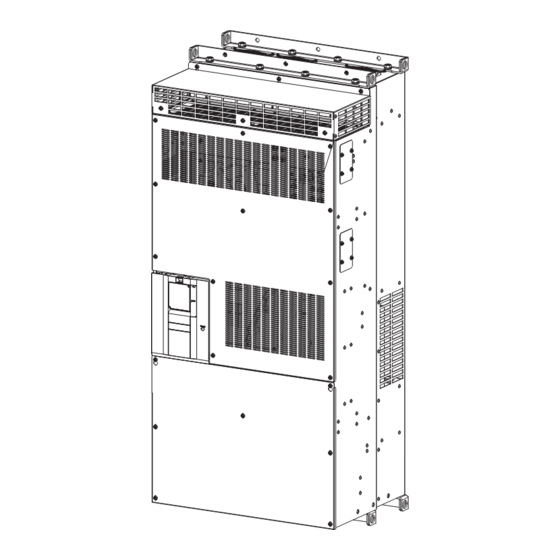
Page 179: Outline Dimension Drawings
Outline dimension drawings 8.3.1 Converter unit outline dimension drawings FR-CC2-H315K, H355K 3×I12 hole 8×I25 hole (100) (Unit: mm) 8. SPECIFICATIONS 8.3 Outline dimension drawings... - Page 180 FR-CC2-H400K, H450K, H500K, H560K, H630K 3×I12 hole 8×I25 hole (100) (Unit: mm) Do not remove the cover on the side of the converter unit. 8. SPECIFICATIONS 8.3 Outline dimension drawings...
- Page 181 MEMO 8. SPECIFICATIONS 8.3 Outline dimension drawings...
- Page 182 CHAPTER 9 APPENDIX Instruction code list ...............................182 Instructions for compliance with the EU Directives....................184 Instructions for UL and cUL ..........................187 Instructions for EAC..............................189 Restricted Use of Hazardous Substances in Electronic and Electrical Products..........190 Referenced Standard (Requirement of Chinese standardized law) ..............191 Compliance with the UK certification scheme.......................191 UL-certified combinations of converter units and inverters...................191...
-
Page 183: Chapter 9 Appendix
APPENDIX APPENDIX provides the reference information for use of this product. Refer to APPENDIX as required. Instruction code list Instruction codes are used to read and write parameters in accordance with the Mitsubishi inverter protocol of RS-485 communication. (For RS- 485 communication, refer to page 118.) - Page 184 Instruction Parameter code Name RS-485 communication retry ○ ○ ○ count RS-485 communication check ○ ○ ○ time interval RS-485 communication waiting ○ ○ ○ time setting RS-485 communication CR/LF ○ ○ ○ selection Communication EEPROM write ○ ○ ○ selection Communication error ×...
-
Page 185: Instructions For Compliance With The Eu Directives
CE marking. • The authorized representative in the EU The authorized representative in the EU is shown below. Name: Mitsubishi Electric Europe B.V. Address: Mitsubishi-Electric-Platz 1, 40882 Ratingen, Germany • Note We declare that this converter unit conforms with the EMC Directive in industrial environments and affix the CE marking on the converter unit. - Page 186 • Use the cable sizes on page 38 under the following conditions. • Surrounding air temperature: 40°C maximum If conditions are different from above, select appropriate wire according to EN 60204-1 or IEC 60364-5-52. • Use a tinned (plating should not include zinc) crimping terminal to connect the earth (ground) cable. When tightening the screw, be careful not to damage the threads.
- Page 187 S2/L22 T2/L32 Provide an appropriate fuse in accordance with the table below. Converter model Fuse type Model Manufacturer Rating FR-CC2-H315K 170M6011, 170M6111 700 A, 700 VAC FR-CC2-H355K 170M6012, 170M6112 800 A, 700 VAC FR-CC2-H400K 170M6013, 170M6113 900 A, 700 VAC...
-
Page 188: Instructions For Ul And Cul
For installation in Canada, branch circuit protection must be provided in accordance with the Canadian Electrical Code and any applicable provincial codes. Provide an appropriate fuse in accordance with the table below. Converter model Fuse type Model Manufacturer Rating FR-CC2-H315K 170M6011, 170M6111 700 A, 700 VAC FR-CC2-H355K 170M6012, 170M6112 800 A, 700 VAC FR-CC2-H400K 170M6013, 170M6113... - Page 189 Short circuit ratings Suitable for use in a circuit capable of delivering not more than 100 kA rms symmetrical amperes, 500 V maximum. 9. APPENDIX 9.3 Instructions for UL and cUL...
-
Page 190: Instructions For Eac
13.) • Authorized sales representative (importer) in the CU area The authorized sales representative (importer) in the CU area is shown below. Name: Mitsubishi Electric (Russia) LLC Address: 52, bld 1 Kosmodamianskaya Nab 115054, Moscow, Russia Phone: +7 (495) 721-2070 Fax: +7 (495) 721-2071 9. -
Page 191: Restricted Use Of Hazardous Substances In Electronic And Electrical Products
Restricted Use of Hazardous Substances in Electronic and Electrical Products The mark of restricted use of hazardous substances in electronic and electrical products is applied to the product as follows based on the "Management Methods for the Restriction of the Use of Hazardous Substances in Electrical and Electronic Products"... -
Page 192: Referenced Standard (Requirement Of Chinese Standardized Law)
To use converter units with inverters, refer to the "Compatible inverters" section in 2.1.2 Peripheral devices (page 20). Other Mitsubishi Electric inverters are also available. For details, contact the nearest Mitsubishi Electric FA center. 9. APPENDIX 9.6 Referenced Standard (Requirement of Chinese standardized law) - Page 193 MEMO 9. APPENDIX 9.8 UL-certified combinations of converter units and inverters...
- Page 194 (1) Damages caused by any cause found not to be the responsibility of Mitsubishi Electric. (2) Loss in opportunity, lost profits incurred to the user by Failures of Mitsubishi Electric products. (3) Special damages and secondary damages whether foreseeable or not, compensation for accidents, and compensation for damages to products other than Mitsubishi Electric products.
- Page 195 REVISIONS *The manual number is given on the bottom left of the back cover. Revision date Manual number Revision Feb. 2014 IB(NA)-0600543ENG-A First edition Jul. 2014 IB(NA)-0600543ENG-B Addition • FR-CC2-H560K, H630K Feb. 2019 IB(NA)-0600543ENG-C Addition • 12-phase rectification • Instructions for EAC •...
- Page 196 FR-CC2 INSTRUCTION Model MANUAL Model code 1A2-P73 HEAD OFFICE: TOKYO BUILDING 2-7-3, MARUNOUCHI, CHIYODA-KU, TOKYO 100-8310, JAPAN IB(NA)-0600543ENG-D(2107)MEE Printed in Japan Specifications subject to change without notice.
Need help?
Do you have a question about the FR-CC2-H315K and is the answer not in the manual?
Questions and answers