
Related Manuals for Sony Trinitron BVM-A14F5U


Summary of Contents for Sony Trinitron BVM-A14F5U
- Page 1 TRINITRON COLOR VIDEO MONITOR ® BVM-A14F5U BVM-A14F5M BVM-A14F5A OPERATION MANUAL [Japanese/English] 1st Edition (Revised 1) Serial No. 2000001 and Higher...
- Page 2 • • •...
- Page 3 ..........................5 ..........................6 ............8 ............................9 ..........................9 ........................10 ..................11 ....................12 ........................ 13 ........................... 13 ........................... 17 ................19 ................19 ...................... 21 ............................21 ....................22 ..............22 ........................23 ......................24 ....................24 ..................
- Page 4 ........41 ...........................41 ..........42 ......................42 ............45 ...........................45 ..........45 ......................46 ..........50 ...........................50 ............50 ......................50 ...........52 ...........................52 ..................52 ......................53 ............54 ...........................54 ................54 ......................54 ...............55 ...........................55 ......................55 ............................56 .........................63...
- Page 5 • • • • • • •...
- Page 6 • • • • •...
- Page 8 • • • • • • •...
- Page 9 ® ®...
- Page 10 • • • • •...
- Page 12 • • •...
- Page 13 INPUT...
- Page 14 • REMOTE GROUP SINGLE • MENU ENTER DOWN MANUAL CONTRAST BRIGHT MANUAL MANUAL CHROMA • • PHASE MANUAL...
- Page 15 SINGLE GROUP 16 : 9 EXT SYNC BLUE ONLY R OFF MONO G OFF B OFF COMB MARKER CHAR OFF CHROMA UP COL TEMP • • • • • •...
- Page 18 • • •...
- Page 19 • • •...
- Page 20 • • • • • • • • • • • • • • • •...
- Page 21 • • • • • • •...
- Page 22 INPUT SINGLE GROUP REMOTE SINGLE GROUP MANUAL CONTRAST BRIGHT MANUAL CHROMA MANUAL MANUAL PHASE MENU ENTER DOWN...
- Page 23 S E L E C T S E T T I N G J A P A N C O L O R T E M P : D 9 3 O T H E R A R E A C O L O R T E M P : D 6 5 •...
- Page 24 INPUT REMOTE SINGLE GROUP CONTRAST MANUAL BRIGHT MANUAL MANUAL CHROMA MANUAL PHASE MENU DOWN ENTER...
- Page 25 M E NU P I CT U R E A D J . . . C O LO R TE M P A D J . .. I N PU T CO N F I G U R A TI O N .. . S Y ST E M C O N F I G U R AT I O N.
- Page 26 I N P UT C ON F I G UR A TI ON C H01 APERT U R E OF F V A LU E 0 00 YC SE P - -- NTSC C O MB F I L T E R - -- MARKE R D IS P L A Y O FF...
- Page 27 C H A N N E L N A M E C H 0 1 P R O G E D I T C A M V T R P R E V N E W N A M E CH A N N EL NA ME C H 01 P RO G...
- Page 28 [A1] [A2] [A3] [B1] [B2] [B3] [B4] [B5] [C1] [C2] [C3] [C4] [C5]...
- Page 29 [D1] [D2] [D3] [D4] [D5] [D6] [D7] [E1] [E2] [E3] [F1] [F2] [F3] [F4] [G1] [G2] [G3] [H1] [H2]...
- Page 30 • • • INPUT CONFIGURATION • PRESET1 PRESET2 PRESET3 PRESET4 PRESET5 MENU • • ENTER (Ent) [A1] [A11] MENU [A2] INPUT CONFIGURATION [A3] [A31] [A32] A321] k[A1] [A33] [A331] k[A2] k[A3]...
- Page 31 [A1] k[A11] INPUT CONFIGURATION ITU601 SMPTE 240M ITU709 USER 1 ITU601 SMPTE 240M ITU709 • ITU601* SMPTE 240M* ITU709* MENU • [A11] ENTER (Ent) [A2] MENU INPUT CONFIGURATION...
- Page 32 [A3] k[A31] k[A32] k[A33] A31] • • [A32] k[A321] [A321] [A33] k[A331] [A331] • [A1]...
- Page 33 INPUT CONFIGURATION [B1] [B11] MENU [B2] [B21] ENTER (Ent) [B3] MENU [B31] [B32] [B321] [B33] [B331] INPUT CONFIGURATION [B4] [B5] k[B1] k[B2] k[B3] • k[B4] k[B5] [B1] • k[B11]...
- Page 34 [B2] k[B21] [B11] • • • 1 2 3...
- Page 35 [B33] k[B331] [B331] [B21] [B2] [B4] [B3] k[B31] k[B32] k[B33] [B31] [B5] [B32] k[B321] [B321]...
- Page 36 • • • • • • • • • • • • • • • • • •...
- Page 37 • [C1] [C11] [C12] [C13] • [C14] [C15] [C2] k[C1] [C3] [C4] [C5] [C51] [C52] [C521] [C53] [C531]...
- Page 38 k[C2] [C11] k[C3] [C12] k[C4] k[C5] [C13] [C1] k[C11] k[C12] k[C13] k[C14] k[C15]...
- Page 39 [C14] [C1] [C3] [C15] [C2]...
- Page 41 [C4] [C5] • k[C51] • k[C52] • k[C53] • [C51] • • [C52] • k[C521] [C521] [C53] k[C531] [C531]...
- Page 42 k[D1] k[D2] [D1] k[D3] [D11] k[D4] [D2] k[D5] [D21] [D211] [D3] k[D6] k[D7] [D1] [D4] [D5] k[D11] [D11] [D6] [D61] [D611] [D62] [D621] [D7] • • [D2] k[D21]...
- Page 43 [D21] [D3] k[D211] [D211] [D4] [D5]...
- Page 44 [D62] k[D621] [D621] [D6] [D7] k[D61] k[D62] [D61] k[D611] [D611]...
- Page 45 [E1] [E11] [E2] • • • [E31] [E311] [E3] [E32] [E33]...
- Page 46 • • k[E1] k[E2] k[E3] [E1] k[E11] [E11] [E2]...
- Page 47 [E3] k[E31] k[E32] k[E33]...
- Page 48 [E31] k[E311] [E32] [E311] [E33] [E31]...
- Page 50 • • • k[F1] k[F2] • k[F3] • k[F4] • [F1] k[F11] [F1] [F111] [F11] [F11] [F2] [F21] [F211] k[F111] [F22] [F221] [F3] [F31] [F311] [F111] [F4] [F41] [F42] [F2] [F43] [F431] k[F21]...
- Page 51 [F4] k[F22] [F21] k[F211] k[F41] [F211] k[F42] k[F43] [F41] [F22] [F42] k[F221] [F221] [F3] [F43] k[F31] k[F431] [F31] k[F311] [F311]...
- Page 52 [F431] • • [G1] [G2] [G3]...
- Page 53 [G1] • • [G2] k[G1] [G3] k[G2] k[G3]...
- Page 54 k[H1] k[H2] [H1] [H2] • • • [H1] [H2] • •...
- Page 55 •...
- Page 60 ø30 ø30...
- Page 61 N.C. N.C. N.C. N.C. N.C. N.C. N.C. N.C. N.C. N.C. 8~25 N.C.
- Page 62 N.C. N.C. N.C. N.C. N.C. N.C. N.C. N.C. N.C. N.C. N.C. N.C. N.C. N.C. N.C. 8~15 N.C.
- Page 63 [E2] [B5] [D62] [A1] [B2] [A11] [B21] [E32] [E33] [F41] [D4] [G1] [D61] [C4] [C15] [C13] [G3] [A3] [B3] [C5] [F2] [F4] [F3] [F31] [E3] [C12] [C1] [E1]...
- Page 64 [D7] [B1] [E31] [A2] [B11] [E311] [C2] [A33] [B33] [C53] [F111] [F22] [F311] [C3] [B321] [H1] [D1] [D11] [H2] [D5] [C51] [A32] [B32] [C52] [F21] [F211] [D2] [D6] [D3] [A31] [B31] [F43] [B4] [E11] [F42] [F1] [F11] [C11] [G2] [C14] [D21]...
- Page 66 WARNING THIS APPARATUS MUST BE EARTHED. For the customers in USA (BVM-A14F5U) AVERTISSEMENT This equipment has been tested and found to comply with the Afin de réduire les risques d’incendie ou d’électrocution, limits for a Class A digital device, pursuant to Part 15 of the ne pas exposer cet appareil à...
- Page 67 Pour les clients européens (BVM-A14F5M/BVM- A14F5A) Ce produit portant la marque CE est conforme à la fois à la Directive sur la compatibilité électromagnétique (EMC) (89/ 336/CEE) et à la Directive sur les basses tensions (73/23/ CEE) émises par la Commission de la Communauté européenne.
-
Page 68: Table Of Contents
Table of Contents Chapter 1 Overview Precautions ................6 Overview ................7 Features..................7 Options ..................8 Connector Panel Configuration ..........9 Installing a Decoder Adaptor............ 10 Location and Function of Parts ......... 11 Front Panel................11 Rear Panel................. 15 Inserting/Ejecting the “Memory Stick”... - Page 69 [C] Setting the Input Configuration – INPUT CONFIGURATION Menu ......34 Overview...................34 Structure of the INPUT CONFIGURATION Menu....35 Setting Lists in the INPUT CONFIGURATION Menu ...35 [D] System Configuration – SYSTEM CONFIGURATION Menu ......39 Overview...................39 Structure of the SYSTEM CONFIGURATION Menu.....40 Setting Lists in the SYSTEM CONFIGURATION Menu ..40 [E] Installation Settings –...
-
Page 70: Chapter 1 Overview
• Operate the unit only with a power source as specified in If you have any questions about this unit, contact your “Specifications” section. authorized Sony dealer. • The nameplate indicating operating voltage, power consumption, etc., is located at the rear. -
Page 71: Overview
On displaying the 4:3 signal Multiformat The monitor supports the principal formats (480I/480P/ The 16:9 mask has been attached to the BVM-A14F5U/ 720P/1080I) for the digital broadcasts, NTSC and PAL A14F5M/A14F5A at the factory. If the 16:9 button is color systems whose horizontal frequency is between pressed to change to the 4:3 aspect mode in this condition, 15.625 kHz and 45 kHz. -
Page 72: Options
Setup and adjustment with the “Memory Stick” Other features (available in software version 1.10 or higher) • Has relay contact parallel remote control connector. You can use a “Memory Stick” to save and load monitor • Built-in test signal generator for crosshatch, 100% white setup and adjustment data. -
Page 73: Connector Panel Configuration
BKM-62HS HD SDI/SDI Input Adaptor Input SDI/ HD SDI/SDI Analog Includes a decoder for HD serial digital signals and serial Adaptor Analog Input Component digital component (525/625) signals and input/output Multi Input Adaptor Input Input connectors for two serial digital signal. Dual-Link input is Adaptor BKM-62HS Adaptor... -
Page 74: Installing A Decoder Adaptor
Push the adaptor in until it is firmly seated in the Installing a Decoder Adaptor connector inside the monitor, then tighten the two screws to secure the adaptor. Each decoder adaptor can be installed in any input option slot on the rear panel. Note Turn off the main power of the monitor and disconnect the AC power cord before installing or removing adaptors. -
Page 75: Location And Function Of Parts
Location and Function of Parts Front Panel 1 Tally lamp 2 DEGAUSS button qa Monitor select 3 I/1 switch lamps and window 4 Numeric keypad 5 Monitor select buttons qs Function buttons 6 MANUAL adjustment buttons and knobs qd “Memory Stick” 7 Menu operation buttons insertion slot 8 OPERATE lamp... - Page 76 e Monitor select buttons g Menu operation buttons When multiple monitors are connected by the network connection, one particular monitor, monitor group or all MENU button: Press to display the monitor menus. monitors are selected by setting the MONITOR ID No., MENU GROUP ID No.
-
Page 77: Function Buttons
l Function buttons For information about the INPUT CONFIGURATION Change the operation conditions for the monitor. menu, see “ Setting the Input Configuration – INPUT Each time the button is pressed, the LED turns on and turns CONFIGURATION Menu” on page 34. off, and the operation conditions are changed. - Page 78 MARKER button: When this button is pushed in (ON), a marker is displayed on the screen. The display mode of the marker is set in the MARKER MODE menu of the INPUT CONFIGURATION menu. For information about the MARKER MODE menu, see “...
-
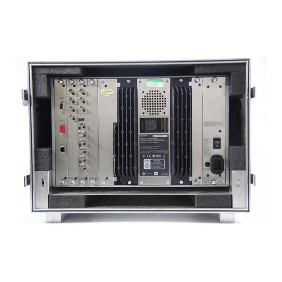
Page 79: Rear Panel
Rear Panel 4 Input option slots 5 PARALLEL REMOTE connector 6 SERVICE connector 1 MAIN POWER switch 7 LAN (10/100) connector 2 AC IN socket 3 Fuse a MAIN POWER switch e PARALLEL REMOTE connector (female, D-sub When turned on, the monitor enters operation mode. By 9-pin) setting in the SYSTEM CONFIGURATION menu, the Forms a parallel switch and controls the monitor... - Page 80 g LAN (10/100) connector (10BASE-T/100BASE-TX) For information about the PARALLEL REMOTE menu, see “ System Configuration – SYSTEM Connect to the network by using a 10BASE-T/100BASE- CONFIGURATION Menu” on page 39. TX LAN cable (shield type, optional). CAUTION To switch each function between on and off or between •...
-
Page 81: Inserting/Ejecting The "Memory Stick
Duo”, , and with a system which automatically measures the size of an trademarks of Sony Corporation. inserted medium. For this reason, both the standard-size “Memory Stick” is a compact, portable and versatile IC “Memory Stick” and smaller “Memory Stick Duo”/ (Integrated Circuit) recording medium with a data capacity “Memory Stick PRO Duo”... - Page 82 – If you use a “Memory Stick” near static electricity or MagicGate is copyright protection technology developed a magnetic field by Sony Corporation. • We recommend backing up important data. • Do not attach anything other than the supplied label to Before using a “Memory Stick”...
-
Page 83: Installation Of The 4:3 Mask
Installation of the 4:3 Connections Mask Connecting to the Network When the aspect ratio is switched from 16:9 to 4:3, replace Monitor Monitor the 16:9 mask with the supplied 4:3 mask. Installing the 4:3 mask Remove the 16:9 mask. LAN (10/100) LAN (10/100) connector connector Switching hub... -
Page 84: Single Group All
Selecting the Monitor/Group When the multiple monitors are connected by the network With the NETWORK menu, each monitor can be set with connections, you can connect the monitors from the control a monitor ID No. or group ID No., between 1 and 99. unit by designating the monitor ID No. -
Page 85: Remote Connection
Remote connection Selecting the Default Set the different IP address to each monitor. Settings Set the different monitor ID No. to each monitor and if necessary, group ID No.. BVM-A14F5M only Select the connection mode by pressing the SINGLE, When you turn on the unit for the first time after purchasing GROUP or ALL button. -
Page 86: Chapter 2 Menu
Menu Chapter Basic Menu Operations Menu Operation Buttons The functions of the menu operation buttons are described INPUT below. Function Button 1 Numeric buttons 1 Numeric buttons Enters the numerical values. 2 Ent button Executes the items selected and settings. 2 Ent button 3 Del button Deletes the values and characters... -
Page 87: Displaying The Menu
Displaying the Menu Menu Operation Press the MENU button. Follow the steps described below to display the menu and The main menu is displayed on the screen. perform the adjustment or setup you wish. Press the MENU button. ME N U The main menu is displayed. - Page 88 Repeat steps 2 and 3 until the desired menu is Choosing one of two or more selections displayed. Selecting in setting mode For more information about setting and adjustments, see below. Using the UP or DOWN button or PHASE knob, move the cursor to the desired item and press the ENTER or Ent button.
-
Page 89: Entering Characters
Entering a numerical value Press the ENTER or Ent button. “?” is displayed in yellow. The “?” indicates the Using the UP or DOWN button or PHASE knob, move position where character input is possible. the cursor to the desired item and press the ENTER or Ent button. -
Page 90: Menu Structure
Menu Structure The main menu and Level 1 are shown below. Detailed information on the menu levels is described at the top of each menu explanation. Main menu Level 1 Functions PICTURE ADJ [A] Adjusts the picture. (page 28) PRESET VALUE Selects the preset data to be adjusted. - Page 91 Main menu Level 1 Functions SYSTEM CONFIGURATION [D] Sets the system of the remote control function, LAN, etc. (page NETWORK [D1] Sets the IP address, subnet mask and default gateway. (page 40) PARALLEL REMOTE [D2] Sets the remote control function. (page 41) POWER [D3] Sets the condition of the monitor when the main power or I/1 switch is turned on.
-
Page 92: [A] Picture Adjustment - Picture Adj Menu
Setting Lists in the PICTURE ADJ [A] Picture Adjustment Menu – PICTURE ADJ Menu This section explains the setting lists displayed in the menu. How to read the setting lists Overview • For purposes of explanation, each setting list is preceded by a menu number. - Page 93 MANUAL ADJUST: Set the picture adjustment COLOR BAR: Select the color bar signal. preset values for the phase/chroma/brightness/ FULL FIELD 8: 100% full-field 8-color bar contrast with the MANUAL knobs. k[A2] (white, yellow, cyan, green, magenta, red, blue COPY FROM...: Copy the other picture preset data. and black) (Default) k[A3] SMPTE: SMPTE standard color bar...
-
Page 94: Color Temp Adj Menu
• Automatic adjustment (AUTO... menu) You can use the following probes for automatic adjustment [A321] OTHER MONITOR menu of color temperature. Except for the Sony BKM-14L, a Copy data from another selected monitor. cable is required to connect the color analyzer to the Select one from among PRESET1, PRESET2, PRESET3, monitor. -
Page 95: Structure Of The Color Temp Adj Menu
[B] COLOR TEMP ADJ menu Structure of the COLOR TEMP ADJ PRESET VALUE: The color temperature data set in Menu the INPUT CONFIGURATION menu is displayed. To change the color temperature data to be adjusted, select from D93, D65, D61, USER1, Level 1 Level 2 Level 3... - Page 96 Knobs for each adjustment • If you cannot execute an AUTO ADJUST menu After adjustment, press the ENTER or Ent button to operation when using the Sony BKM-14L probe, confirm the setting. try again after disconnecting and reconnecting RED: CONTRAST KNOB (Adjust the R gain or bias the probe.
- Page 97 [B21] AUTO ADJUST menu [B33] MEMORY STICK... menu This menu is displayed when AUDO ADJUST is selected Select the file in the “Memory Stick”. k[B331] in the [B2] AUTO... menu. [B331] MEMORY STICK menu The following message appears. SET PROBE ON CURSOR Select the data from a file in the “Memory Stick”...
-
Page 98: Input Configuration Menu
Channels 80 to 89 assignment [C] Setting the Input The channel numbers from 80 to 89 are assigned to switch the signal system of the internal signals. Configuration – INPUT The channels 80 to 89 can be selected after selecting channels 91 to 97 and the internal signal of the selected CONFIGURATION Menu signal system is output. -
Page 99: Structure Of The Input Configuration Menu
Setting Lists in the INPUT Notes CONFIGURATION Menu When FORMAT... is set to the following, you cannot select the input number. This section explains the setting lists displayed in the – when BKM-61D is installed and Analog Y/C signal is menu. - Page 100 VALUE: Enter the aperture adjustment value (0 to LEVEL (0 % or 7.5 %) (default setting is 7.5 % for 200) (default setting is 000). BVM-A14F5U, 0 % for BVM-A14F5M/A14F5A). YC SEP: Select Y/C separation filter. FILTER SW: Set the Y/C separation filter (OFF or COMB: Use the comb filter (default).
- Page 101 ASPECT MARKER is set to ON. SETUP LEVEL (0 % or 7.5 %) (default setting is Set to THICK or THIN (default setting is THICK). 7.5 % for BVM-A14F5U, 0 % for BVM-A14F5M/ COLOR: Set the color of the aspect marker when A14F5A).
- Page 102 MARKER MODE (2/3) menu Example: Safe area size 80%, ASPECT MODE 16:9 or Set the safe area marker or center marker. SAFE AREA MARKER: Select whether or not to with 16:9 button ON with 16:9 button OFF display the safe area. Set to OFF (not display) or ON (display) (default ASPECT setting is ON).
-
Page 103: [D] System Configuration
[C5] COPY FROM menu (available in software version [D] System Configuration 1.10 or higher) Select the source to be copied from. – SYSTEM OTHER CH...: Copy other data in this monitor. k[C51] CONFIGURATION Menu OTHER MONITOR... : Copy data from another monitor. -
Page 104: Structure Of The System Configuration Menu
Structure of the SYSTEM Setting Lists in the SYSTEM CONFIGURATION Menu CONFIGURATION Menu This section explains the setting lists displayed in the Level 1 Level 2 Level 3 menu. NETWORK... [D1] MONITOR ID How to read the settin lists GROUP ID •... - Page 105 [D11] NETWORK SETTINGS... menu PARALLEL REMOTE (2/2) menu IP ADDRESS: Set the IP address (default is BLUE ONLY: Set the blue signal pictures display “192.168.000.001”). (monochrome) on or off. SUBNET MASK: Set the subnet mask (default is R OFF: Set cutting red beams enabled or disabled. “255.255.255.000”).
- Page 106 [D5] ON SCREEN SET... menu [D62] APPLY PASSWORD... menu Set the data about the screen display. Select whether or not to apply the password to each menu. FORMAT DISPLAY: Select the display mode of the PICTURE ADJ: Select YES or NO. signal system.
-
Page 107: [E] Installation Settings
Structure of the INSTALLATION [E] Installation Settings SETTINGS Menu – INSTALLATION SETTINGS Menu Level 1 Level 2 Level 3 LANDING ADJUST... [E1] RESTORE FACTORY DATA [E11] Overview ALIGNMENT... [E2] ROTATION H PHASE Initial settings of geometry, convergence, etc. are adjusted V CENTER from this menu. -
Page 108: Setting Lists In The Installation Settings Menu
[E2] ALIGNMENT... menu Setting Lists in the INSTALLATION Adjust the position size or geometry of the picture or SETTINGS Menu convergence with the UP and DOWN buttons or PHASE knob. This section explains the setting lists displayed in the menu. ALIGNMENT (1/3) menu Adjust the position or size of the picture of the monitored How to read the setting lists... - Page 109 AUTO FULL POINTS ADJ: Automatically adjust sides of the picture. the whole area of the screen in sequence using the Sony BKM-14L Auto Setup Probe. k[E32] (available in software version 1.10 or higher) AUTO ONE POINT ADJ: Automatically adjust only the selected adjustment point of the screen using the Sony BKM-14L Auto Setup Probe.
- Page 110 Automatically adjust only the selected adjustment point of MANUAL button. the screen using the Sony BKM-14L Auto Setup Probe. To cancel adjustment Before entering the AUTO ONE POINT ADJ menu, Press the MENU button. The adjusted data is cleared and connect the BKM-14L to the OPTION connector.
-
Page 111: [F] System Data Operation
Note [F] System Data Operation If you press the ENTER or Ent button without moving – FILE MANAGEMENT the cursor, the screen returns to the DIGITAL UNIFORMITY ADJ... menu. Menu 2 Place the BKM-14L on the cursor displayed in the center of the screen. -
Page 112: Setting Lists In The File Management Menu
[F21] OTHER MONITOR... menu Setting Lists in the FILE Copy the data from other monitor. MANAGEMENT Menu Select the monitor ID. k[F211] This section explains the setting lists displayed in the [F211] OTHER MONITOR menu menu. Select the data to be copied. ALL: Copy all data. -
Page 113: [G] Displaying Information On The Monitor
[F42] RE-STORE SYSTEM DATA menu (available in [G] Displaying software version 1.10 or higher) The following message appears to confirm the data restore Information On the operation. ALL DATA WILL BE RESTORED Monitor – STATUS Menu AND MONITOR WILL RESTART ARE YOU SURE? OK: To continue, press the ENTER or Ent button. -
Page 114: Setting Lists In The Status Menu
[G1] CH STATUS... menu Setting Lists in the STATUS Menu Display the information on the used channel. The information of the assigned internal signal is displayed This section explains the setting lists displayed in the on the channels 80 to 89 and 91 to 97. menu. -
Page 115: [H] Setting The Controller - Controller Menu
ON: Always displayed (default). Note AUTO: Displayed during operating by the remote When the BVM-A14F5U/A14F5M/A14F5A is used as the connection and cleared after operation controller, the NETWORK SETTINGS... menu and the OFF: Not displayed. NETWORK SW menu cannot be selected. -
Page 116: [I] Setting Key Protect - Key Protect Menu
[I] Setting Key Protect – KEY PROTECT Menu Overview The data is locked so that they cannot be changed by an unauthorized user. Setting Lists in the KEY PROTECT Menu This section explains the setting lists displayed in the menu. How to read the setting lists •... -
Page 117: Appendixes
OPTION: Mini-DIN 8-pin (female) × 1 Anode voltage: PARALLEL REMOTE: D-sub 9-pin 25 kV with no beam current (female) × 1 Nominal chromaticity coordinates: SERVICE: D-sub 9-pin (male) × 1 LAN (10BASE-T/100BASE-TX): SMPTE C phosphor (BVM-A14F5U) RJ-45 × 1 0.630 0.340 0.310 0.595 0.155 0.075 Error: ±... -
Page 118: Operating Conditions
Video signal Operating conditions Differential gain Temperature 0°C to 35°C (32°F to 95°F) Less than 5% (for luminance from 0 to Optimum temperature 100 cd/m 20°C to 30°C (68°F to 86°F) Differential phase Humidity 0% to 90% (no condensation) Less than 5° (for luminance from 0 to 100 Pressure 700 hPa to 1060 hPa cd/m... -
Page 119: Available Signal Systems
Available Signal Systems System Total lines Active lines Frame rate (Hz) Scanning Aspect Standard Display on per frame per frame format ratio the monitor* 575/50I 2:1 interlace 16:9/4:3 Rec ITU-R BT.601 575/50I 480/59.94I 30/1.001 2:1 interlace 16:9/4:3 Rec ITU-R BT.601 480/60I 576/50P Progressive... -
Page 120: Available Signal Formats
Available Signal Formats Signal format System BKM-61D BKM-62HS BKM-68X Standard Analog Composite Setup × × NTSC 480/59.94I SMPTE 170M level × × 575/50I Rec.ITU-R BT.470 × × PAL-M 480/59.94I Rec.ITU-R BT.470 × × SECAM 575/50I Rec.ITU-R BT.470 Analog (Y/C) Setup ×... - Page 121 Signal format System BKM-61D BKM-62HS BKM-68X Standard × 480/59.94I SMPTE 259M × 575/50I Setup × × NTSC 480/59.94I level SMPTE 259M × × 575/50I HD SDI (10 bit system only) × × Single Link 4:2:2 YPBPR 1035/60I* SMPTE 292M Single Link 4:2:2 YPBPR SMPTE 292M...
-
Page 122: Dimensional Drawing
Left Side Dimensional Drawing Unit: mm (inches) 500 (19 28 (1 185 (7 426 (16 8.5 ( ø30 370 (14 Rear Front 340 (13 426 (16 482 (19) 28 (1 340 (13 Right Side 500 (19 28 (1 378 (15) ø30 370 (14 Specifications... -
Page 123: Connection Cable Specifications
Connection Cable Specifications for Color Temperature Probes Special cables are required to connect color temperature The following diagrams show specifications and pin probes other than the Sony BKM-14L to the monitor. assignments for the required cables. Connection cable for UDT INSTRUMENTS SLS 9400-FC probe... - Page 124 Connection cable for KONICA MINOLTA CA-100plus probe Mini DIN 8-pin connector D-sub 9-pin connector (male) (male) Pin Number Signal Signal Pin Number N.C. N.C. N.C. Connection cable for DK-TECHNOLOGIES PM 5639 probe (corresponds to DK-TECHNOLOGIES PM 5639/00 cable) Modular connector Mini DIN 8-pin connector (male) Signal...
-
Page 125: Menu Index
Menu Index The menu index shows the menu items provided with this the item is explained, its menu number, and the main menu monitor in alphabetical order. For you reference, each that the item belongs to. menu item is followed by the page of this manual on which Menu Item Page Menu number... - Page 126 Menu Item Page Menu number Main menu MAINTENANCE [D7] SYSTEM CONFIGURATION menu MANUAL [B1] COLOR TEMP ADJ menu [E31] INSTALLATION SETTINGS menu MANUAL ADJUST [A2] PICTURE ADJ menu [B11] COLOR TEMP ADJ menu [E311] INSTALLATION SETTINGS menu [C2] MATRIX INPUT CONFIGURATION menu MEMORY STICK [A33] PICTURE ADJ menu...
- Page 127 Menu Item Page Menu number Main menu SAVE TO [F1] FILE MANAGEMENT menu SAVE TO MEMORY STICK [F11] FILE MANAGEMENT menu [C11] SDI/HD-SDI INPUT CONFIGURATION menu SLOT STATUS [G2] STATUS menu STATUS STATUS menu SYSTEM CONFIGURATION SYSTEM CONFIGURATION menu THOMA COLOR TEMP ADJ menu UDT INSTRUMENTS COLOR TEMP ADJ menu...
- Page 129 The material contained in this manual consists of information that is the property of Sony Corporation and is intended solely for use by the purchasers of the equipment described in this manual. Sony Corporation expressly prohibits the duplication of any...
- Page 130 Sony Corporation BVM-A14F5U/A14F5M/ Printed in Japan A14F5A (UC/JAE/AU) 2006.01 2-593-879-02(2) © 2005...
Need help?
Do you have a question about the Trinitron BVM-A14F5U and is the answer not in the manual?
Questions and answers