Table of Contents
Advertisement
Advertisement
Table of Contents

Related Manuals for Bosch AutoDome 600 Series


Summary of Contents for Bosch AutoDome 600 Series
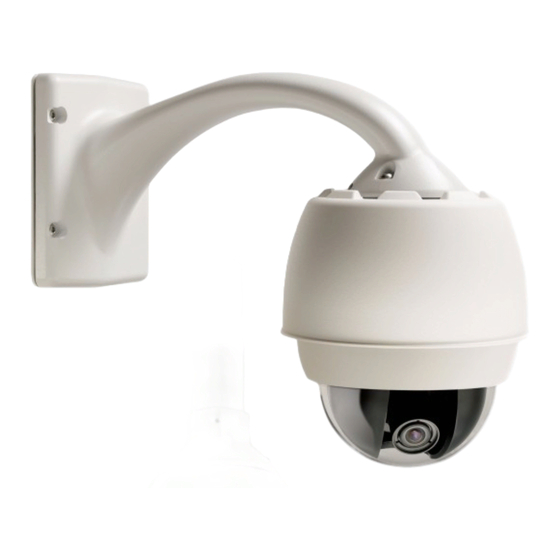
- Page 1 AutoDome 600 Series Analog PTZ Camera AutoDome 600 Series Installation Manual...
-
Page 3: Table Of Contents
AutoDome 600 Series Analog PTZ Camera Table of Contents | en Table of Contents Safety Important Safety Instructions Safety Precautions Important Notices Customer Support and Service Installing the Pendant Arm Wall, Corner, and Mast (Pole) Mounts Unpacking 2.1.1 Parts List 2.1.2... - Page 4 | Table of Contents AutoDome 600 Series Analog PTZ Camera Attach Pendant to Pipe and Tighten 3.10 Make Connections in the Power Supply Box 3.10.1 Connections for Fiber Optic Models Installing the In-Ceiling Mount Unpacking 4.1.1 Parts List 4.1.2 Description 4.1.3...
- Page 5 AutoDome 600 Series Analog PTZ Camera Table of Contents | en Bubble Handling and Cleaning Handling Cleaning 7.2.1 Cleaning the Bubble Interior 7.2.2 Cleaning the Bubble Exterior Installation Notes for AutoTracker Camera Height Mount/Mounting Surfaces Field of View Unwanted Motion Index Bosch Security Systems, Inc.
-
Page 6: Safety
| Safety AutoDome 600 Series Analog PTZ Camera Safety Important Safety Instructions Read, follow, and retain for future reference all of the following safety instructions. Heed all warnings on the unit and in the operating instructions before operating the unit. - Page 7 17. Attachments, changes or modifications - Only use attachments/accessories specified by the manufacturer. Any change or modification of the equipment, not expressly approved by Bosch, could void the warranty or, in the case of an authorization agreement, authority to operate the equipment.
-
Page 8: Safety Precautions
| Safety AutoDome 600 Series Analog PTZ Camera Safety Precautions DANGER! This symbol indicates an imminently hazardous situation such as “Dangerous Voltage” inside the product. If not avoided, this will result in an electrical shock, serious bodily injury, or death. - Page 9 Please dispose of these units at an environmentally compatible recycling facility, per European Directive 2002/96/EC. Environmental statement - Bosch has a strong commitment towards the environment. This unit has been designed to respect the environment as much as possible.
- Page 10 Because the ISDN circuits are treated like telephone-network voltage, avoid connecting the SELV circuit to the Telephone Network Voltage (TNV) circuits. Video loss - Video loss is inherent to digital video recording; therefore, Bosch Security Systems cannot be held liable for any damage that results from missing video information. To minimize the risk of lost digital information, Bosch Security Systems recommends multiple, redundant recording systems, and a procedure to back up all analog and digital information.
- Page 11 UL MAKES NO REPRESENTATIONS, WARRANTIES, OR CERTIFICATIONS WHATSOEVER REGARDING THE PERFORMANCE OR RELIABILITY OF ANY SECURITY OR SIGNALING- RELATED FUNCTIONS OF THIS PRODUCT. Copyright This user guide is the intellectual property of Bosch Security Systems, Inc. and is protected by copyright. All rights reserved. Trademarks All hardware and software product names used in this document are likely to be registered trademarks and must be treated accordingly.
-
Page 12: Customer Support And Service
| Safety AutoDome 600 Series Analog PTZ Camera Customer Support and Service If this unit needs service, contact the nearest Bosch Security Systems Service Center for authorization to return and shipping instructions. Service Centers Telephone: 800-366-2283 or 585-340-4162 Fax: 800-366-1329 Email: cctv.repair@us.bosch.com... -
Page 13: Installing The Pendant Arm Wall, Corner, And Mast (Pole) Mounts
Verify that all the parts listed in the Parts List below are included. If any items are missing, notify your Bosch Security Systems Sales or Customer Service Representative. Refer to Section 1.4 Customer Support and Service, page 12, for contact information. -
Page 14: Description
No. 2 Phillips screwdriver – Socket wrench and 9/16-in. socket – Banding tool (Bosch P/N TC9311PM3T) - if installing a mast (pole) mount – 3/4 in. (20-mm) NPS right angle conduit connector - if installing a mast (pole) mount with a VG4-ARMPLATE... -
Page 15: Mount Power Supply Box
AutoDome 600 Series Analog PTZ Camera Installing the Pendant Arm Wall, Corner, and Mast (Pole) Mounts | en Choose the appropriate mounting kit to use, depending on the location of the AutoDome, either wall mount, corner mount, or mast (pole) mount. -
Page 16: Route Wires And Attach Connectors
Mast Plate to the pole. Contact your Bosch Sales Representative to order Banding Tool P/N TC9311PM3T. Secure the Power Supply Box to the Corner Plate or Mast Plate using the four (4) 3/8 x 1-3/4-inch bolts and split lock washers (supplied). -
Page 17: Coaxial Cable Connections
AutoDome 600 Series Analog PTZ Camera Installing the Pendant Arm Wall, Corner, and Mast (Pole) Mounts | en 2.4.1 Coaxial Cable Connections If you are using coaxial cable to connect an AutoDome to a head-end system, you must use the coaxial cable with ferrite included in the AutoDome packaging. - Page 18 If “daisy chaining” a series of AutoDomes, a terminating resistor is required in the last dome of the series. The Bosch Power Supply Box is supplied with a 100 Ω terminating resistor located between the Biphase terminals C- and C+ (pins 1 and 2) of the P106 control connector.
- Page 19 AutoDome 600 Series Analog PTZ Camera Installing the Pendant Arm Wall, Corner, and Mast (Pole) Mounts | en If you are connecting alarm inputs and outputs, attach the supplied 4- and 6-pin Alarm Connectors with flying lead wires to the appropriate incoming alarm wires.
-
Page 20: Power Supply Box Connections
| Installing the Pendant Arm Wall, Corner, and Mast (Pole) Mounts AutoDome 600 Series Analog PTZ Camera 2.4.3 Power Supply Box Connections The following figure is a detailed illustration of the Pendant Arm Power Supply Box, which includes the fuse specifications. -
Page 21: Route Power Through Intermediate Power Supply Box
AutoDome 600 Series Analog PTZ Camera Installing the Pendant Arm Wall, Corner, and Mast (Pole) Mounts | en The following table lists the Power Supply Box connectors: Connector Pin 1 Pin 2 Pin 3 Pin 4 Pin 5 Pin 6... - Page 22 | Installing the Pendant Arm Wall, Corner, and Mast (Pole) Mounts AutoDome 600 Series Analog PTZ Camera VG4-PSU1 / VG4-PSU2 J102 P101 (LED) 1 2 3 P106 P105 GND TXD RXD C+ C- TXD RXD 6 5 4 3 2 1...
- Page 23 AutoDome 600 Series Analog PTZ Camera Installing the Pendant Arm Wall, Corner, and Mast (Pole) Mounts | en Attach the supplied 3-pin power plug to the incoming high voltage power wires in the box. Refer to connector P101 in Table 2.2, Page 22 and to the image below for an...
- Page 24 | Installing the Pendant Arm Wall, Corner, and Mast (Pole) Mounts AutoDome 600 Series Analog PTZ Camera Attach the supplied 3-pin power plug to the incoming 24 VAC power wires in the box, as illustrated below. J102 P101 (LED)
-
Page 25: Attach Pendant Arm To Power Supply Box
AutoDome 600 Series Analog PTZ Camera Installing the Pendant Arm Wall, Corner, and Mast (Pole) Mounts | en Attach Pendant Arm to Power Supply Box The bottom hinge pin of the Pendant Arm is provided with a Hinge Pin Stop to hold the hinge open while attaching the arm to the Power Supply Box. -
Page 26: Make Connections In Power Supply Box
| Installing the Pendant Arm Wall, Corner, and Mast (Pole) Mounts AutoDome 600 Series Analog PTZ Camera Make Connections in Power Supply Box Refer to Table 2.2, Page 22 to locate the various connectors in the power supply box and make the following connections detailed below. - Page 27 AutoDome 600 Series Analog PTZ Camera Installing the Pendant Arm Wall, Corner, and Mast (Pole) Mounts | en Connect the 5-pin, 24 VAC to Dome Plug from the Pendant Connector Harness to its corresponding color mating connector P107 on the right side of the box.
- Page 28 | Installing the Pendant Arm Wall, Corner, and Mast (Pole) Mounts AutoDome 600 Series Analog PTZ Camera (GND) 24V NC GND TXD RXD C+ C- Figure 2.12 Optional Fiber Optic Module Transformer ST Connector (Fiber) BNC to Dome Power In...
-
Page 29: Installing The Vg4-A-Armplate
Follow the instructions provided with the banding tool to securely mount the Mast Plate to the pole. Contact your Bosch Sales Representative to order Banding Tool P/N TC9311PM3T. -
Page 30: Attach The Pendant Arm To The Mounting Plate
| Installing the Pendant Arm Wall, Corner, and Mast (Pole) Mounts AutoDome 600 Series Analog PTZ Camera 2.8.1 Attach the Pendant Arm to the Mounting Plate The bottom hinge pin of the Pendant Arm is provided with a Hinge Pin Stop to hold the hinge open while attaching the arm to the Mounting Plate. -
Page 31: Route And Connect Wires To A Power Supply Box
AutoDome 600 Series Analog PTZ Camera Installing the Pendant Arm Wall, Corner, and Mast (Pole) Mounts | en 2.8.2 Route and Connect Wires to a Power Supply Box The illustration below depicts the power and control cables connected to the Pendant Arm: Figure 2.14 Pendant Arm Cables... - Page 32 | Installing the Pendant Arm Wall, Corner, and Mast (Pole) Mounts AutoDome 600 Series Analog PTZ Camera Route all incoming wires through one of the conduits at the bottom of the Mounting Plate. For a mast mount, route all wires through the right-angle conduit.
-
Page 33: Prepare Pendant For Installation
AutoDome 600 Series Analog PTZ Camera Installing the Pendant Arm Wall, Corner, and Mast (Pole) Mounts | en 10. If using a coax cable, connect the incoming coax cable to the BNC jack (female connector enclosed by the plastic cover) on the coax cable with ferrite. Slide the plastic cover over the connection. - Page 34 | Installing the Pendant Arm Wall, Corner, and Mast (Pole) Mounts AutoDome 600 Series Analog PTZ Camera Rotate the Bubble Assembly counterclockwise approximately 20 degrees until the bubble assembly releases from the Pendant Housing. Figure 2.16 Pendant Bubble Release Opening Remove the foam inserts surrounding the camera module.
-
Page 35: Attach Pendant To Arm And Tighten
AutoDome 600 Series Analog PTZ Camera Installing the Pendant Arm Wall, Corner, and Mast (Pole) Mounts | en 2.10 Attach Pendant to Arm and Tighten NOTICE! Before attaching the AutoDome Pendant, visually inspect the dome and arm connectors for any blocked pin holes or bent pins. - Page 36 | Installing the Pendant Arm Wall, Corner, and Mast (Pole) Mounts AutoDome 600 Series Analog PTZ Camera Drop the dome housing down slightly to engage the dome housing hook on the Pendant Arm hinge pin, allowing the dome to rotate around the pin.
-
Page 37: Installing Roof Parapet And Pipe Mounts
The VG4-A-9230 Series are stationary mounts intended for rooftop parapet vertical walls. They are made of light weight aluminum with a corrosion-resistant finish and are used for all Bosch AutoDome Cameras up to a rated load of 29 kg (64 lb). These mounts can be fitted to the inside or outside of parapet walls and can swivel for ease of positioning and for servicing the AutoDome. -
Page 38: Tools Required
| Installing Roof Parapet and Pipe Mounts AutoDome 600 Series Analog PTZ Camera 3.1.3 Tools Required – 5 mm Allen wrench (supplied) – Small straight blade screwdrivers ~ 2.5 mm (0.1 in.) – 3.1 mm (1/8 in.) – Medium straight blade screwdriver –... -
Page 39: Mount Power Supply Box
AutoDome 600 Series Analog PTZ Camera Installing Roof Parapet and Pipe Mounts | en Mount Power Supply Box Before mounting the Power Supply Box decide if you will be wiring the box through the holes in the bottom or back of the box. If wiring the box through the back, move the two (2) seal plugs to the bottom holes before mounting. -
Page 40: Attach Cover Door
| Installing Roof Parapet and Pipe Mounts AutoDome 600 Series Analog PTZ Camera 3.3.1 Attach Cover Door Compress the bottom hinge pin by pushing the pin lever down and then rotate it behind the Hinge Pin Stop. The power box Cover Door provides a Hinge Pin Stop to hold the bottom hinge open while attaching the door. -
Page 41: Route Wires And Attach Connectors
AutoDome 600 Series Analog PTZ Camera Installing Roof Parapet and Pipe Mounts | en Route Wires and Attach Connectors Power wires must be routed to the left (front) side of the Power Supply Box through a separate conduit. All video, control, and alarm wires must be routed through a second conduit to the right side of the box. -
Page 42: Methods For Routing Wires
| Installing Roof Parapet and Pipe Mounts AutoDome 600 Series Analog PTZ Camera 3.4.2 Methods for Routing Wires There are two possible methods to route the video, control, and alarm wires: – One is to route the video, control, and alarm wires through the conduit fitting on the right (front) side of the Power Supply Box and out to the AutoDome Interface Board. - Page 43 AutoDome 600 Series Analog PTZ Camera Installing Roof Parapet and Pipe Mounts | en – The second method is to bypass the Power Supply Box and route the video, control, and alarm wires directly to the Interface Board. You connect only the power wires inside the Power Supply Box.
-
Page 44: Wiring The Power Supply Box
| Installing Roof Parapet and Pipe Mounts AutoDome 600 Series Analog PTZ Camera 3.4.3 Wiring the Power Supply Box Route the high voltage 115/230 VAC lines through the conduit fitting on the left side of the box. NOTICE! The Power Supply Box with transformer comes with a barrier that separates the high voltage side on the left from the low voltage 24 VAC side on the right. - Page 45 AutoDome 600 Series Analog PTZ Camera Installing Roof Parapet and Pipe Mounts | en Route the control wires from the Power Supply to the Pipe Interface Board. Then attach the supplied six (6) pin control data connector to the wires in the Power Supply Box.
-
Page 46: Power Supply Box Connections
| Installing Roof Parapet and Pipe Mounts AutoDome 600 Series Analog PTZ Camera 3.4.5 Power Supply Box Connections The following figure is a detailed illustration of the Roof or Pipe Mount Power Supply Box, which includes the fuse specifications. -
Page 47: Installing The Vg4-A-9230 Roof Parapet Mount
AutoDome 600 Series Analog PTZ Camera Installing Roof Parapet and Pipe Mounts | en The following table lists the Power Supply Box connectors: Connector Pin 1 Pin 2 Pin 3 Pin 4 Pin 5 Pin 6 Ground Grounding Screw P101... - Page 48 | Installing Roof Parapet and Pipe Mounts AutoDome 600 Series Analog PTZ Camera Prepare the mounting surface for the type of fastener by drilling holes for the mounting anchors as required. Figure 3.7 Parapet Wall Mount Bracket and Roof Mount Plate...
- Page 49 AutoDome 600 Series Analog PTZ Camera Installing Roof Parapet and Pipe Mounts | en Remove the End Cap from the front of the arm and feed the video, control, and power wires up through the bottom of the pipe arm and out the front end.
-
Page 50: Installing The Vg4-A-9543 Pipe Mount
| Installing Roof Parapet and Pipe Mounts AutoDome 600 Series Analog PTZ Camera 11. Run a bead of RTV Silicon sealant around the down pipe/Dome Cap interface to seal any gaps between the down pipe and the Dome Cap. -
Page 51: Wire The Pipe Interface Board
AutoDome 600 Series Analog PTZ Camera Installing Roof Parapet and Pipe Mounts | en Apply the supplied thread sealant to the threads on the Pipe. – Make sure all surfaces are clean and dry. – Apply a bead of sealant completely around the leading threads of the male fitting. -
Page 52: Wiring For Multiple Autodomes
| Installing Roof Parapet and Pipe Mounts AutoDome 600 Series Analog PTZ Camera Ref. Description Connector Wire Gauge Description Pipe Interface Module Video Coax In J102 6-pin Connector Alarms In (3-7) P103 4-pin Connector Alarms Out (1-3) P102 100 Ω Resistor... - Page 53 AutoDome 600 Series Analog PTZ Camera Installing Roof Parapet and Pipe Mounts | en If using UTP for video, attach an RJ45 connector plug to the UTP cable and connect the plug to its mating connector J101 on the Pipe Interface Board.
-
Page 54: Prepare Pendant For Installation
| Installing Roof Parapet and Pipe Mounts AutoDome 600 Series Analog PTZ Camera Insert the Pipe Interface Board into the down pipe and fasten the three (3) retaining screws to secure the board to the Dome Cap. CAUTION! Be careful not to strip the threads when tightening the Pipe Interface Board retaining screws. - Page 55 AutoDome 600 Series Analog PTZ Camera Installing Roof Parapet and Pipe Mounts | en Rotate the Bubble Assembly counterclockwise approximately 20 degrees until the bubble assembly releases from the Pendant Housing. Figure 3.14 Pendant Bubble Release Opening Remove the foam inserts surrounding the camera module.
-
Page 56: Attach Pendant To Pipe And Tighten
| Installing Roof Parapet and Pipe Mounts AutoDome 600 Series Analog PTZ Camera Attach Pendant to Pipe and Tighten Before attaching the Pendant, visually inspect the Pendant dome and the Interface Board connectors for any blocked pin holes and bent pins. -
Page 57: Make Connections In The Power Supply Box
AutoDome 600 Series Analog PTZ Camera Installing Roof Parapet and Pipe Mounts | en Drop the Pendant down slightly to engage the dome hook and hinge pin of the Dome Cap, allowing the dome to rotate around the hinge pin. -
Page 58: Installing The In-Ceiling Mount
Verify that all the parts listed in the product's Parts List below are included. If any items are missing, notify your Bosch Security Systems Sales or Customer Service Representative. Refer to Section 1.4 Customer Support and Service, page 12, for contact information. -
Page 59: Pre-Installation Check List
AutoDome 600 Series Analog PTZ Camera Installing the In-Ceiling Mount | en Pre-installation Check List Determine the location and distance for the power supply box based on its voltage and current consumption. Refer to Section 5 Cable and Wire Standards, page 70 for specifications. -
Page 60: Prepare Drywall Ceiling For Installation
| Installing the In-Ceiling Mount AutoDome 600 Series Analog PTZ Camera Prepare Drywall Ceiling for Installation Choose the desired location to mount the dome. Use the bracket Base Plate as a template cut a 7 in. hole with a tolerance of ±1/8 in. -
Page 61: Wire The Interface Box
AutoDome 600 Series Analog PTZ Camera Installing the In-Ceiling Mount | en Tighten the four (4) securing screws to the Bracket Assembly. Figure 4.4 Tighten Bracket Securing Screw Secure the Bracket Assembly to an overhead securing point with a safety wire. -
Page 62: Coaxial Cable Connections
| Installing the In-Ceiling Mount AutoDome 600 Series Analog PTZ Camera 4.6.1 Coaxial Cable Connections If you are using coaxial cable to connect an AutoDome to a head-end system, you must use the coaxial cable with ferrite included in the AutoDome packaging. The following illustration shows the components of this cable: Figure 4.6 Coaxial cable with ferrite... - Page 63 AutoDome 600 Series Analog PTZ Camera Installing the In-Ceiling Mount | en Route the coaxial cable with ferrite, which shipped with the AutoDome, inside the Interface Box as shown: Attach a BNC connector to the incoming video coax cable. Connect the incoming coax cable to the BNC jack (female connector enclosed by the plastic cover) on the coax cable with ferrite.
- Page 64 | Installing the In-Ceiling Mount AutoDome 600 Series Analog PTZ Camera 10. To connect alarm inputs and outputs, attach the supplied 6-pin Alarms In and the 4-pin Alarms Out connector plugs with flying leads to the appropriate alarm wires. Then connect the plugs to their mating connectors P103 and P102 in the Interface Box.
-
Page 65: Interface Box Connections
AutoDome 600 Series Analog PTZ Camera Installing the In-Ceiling Mount | en 4.6.3 Interface Box Connections The following figure is a detailed illustration of the In-ceiling Interface box. Figure 4.9 In-ceiling Interface Box Fiber Optics Coax Video UTP/Ethernet Video Alarm In... -
Page 66: Prepare Bubble
| Installing the In-Ceiling Mount AutoDome 600 Series Analog PTZ Camera The following table summarizes the pin connectors and their function: Connector Pin 1 Pin 2 Pin 3 Pin 4 Pin 5 Pin 6 Pin 7 P103 Alarms In... -
Page 67: Attach Housing To The Interface Box
AutoDome 600 Series Analog PTZ Camera Installing the In-Ceiling Mount | en Rotate the bubble clockwise until it locks in position. Refer to Figure 4.11, Page 67. NOTICE! The dome bubble comes assembled with a white trim ring. An optional black trim ring is supplied separately. - Page 68 | Installing the In-Ceiling Mount AutoDome 600 Series Analog PTZ Camera Tighten the two (2) Thumbscrews to secure the Interface Box to the housing. Figure 4.13 In-Ceiling Housing and Interface Box Interface Box Thumb Screw Ball Stud Tether Point...
-
Page 69: Secure Housing To Ceiling
AutoDome 600 Series Analog PTZ Camera Installing the In-Ceiling Mount | en Secure Housing to Ceiling The In-ceiling Housing is secured to the ceiling by two (2) screw clamps. Insert the In-ceiling Mount Assembly through the hole in the ceiling. -
Page 70: Cable And Wire Standards
Bilinx control data can also be sent over the same cable. Bilinx is a Bosch 2-way communication protocol that allows remote control, configuration, and updates over a video coax cable. Bilinx is available on all VG5 100 and 600 Series AutoDomes. -
Page 71: Using Utp To Transmit Video And Control
Bilinx control data can also be sent over the same two video wires (1 & 2). Bilinx is a Bosch 2- way communication protocol that allows remote control, configuration and updates over a passive UTP cable. -
Page 72: Using Multi-Mode Fiber Optic To Transmit Video And Control
Controlling the AutoDome via Biphase (Shielded 2-wire, half-duplex, multi-drop, 5000 ft. cable limit) Biphase is the standard Bosch protocol used to send Pan/Tilt/Zoom control over 2-wire shielded twisted pair (STP) terminated with a 100 Ω terminal resistor. The AutoDome has a 100 Ω termination resistor between the Biphase C+ and C- terminals. - Page 73 AutoDome 600 Series Analog PTZ Camera Cable and Wire Standards | en The figure below illustrates the connections necessary for Biphase operation. 100 Ω Figure 5.2 Connections for Biphase Operation C- (Biphase) AutoDome Data In/Out C+ (Biphase) Head End Biphase...
-
Page 74: Controlling The Autodome Via The Rs232 Protocol
| Cable and Wire Standards AutoDome 600 Series Analog PTZ Camera 5.4.2 Controlling the AutoDome via the RS232 Protocol (3-wire, full-duplex, single-ended, 50 ft. cable limit) RS232 is a common, single-ended communication protocol used for control. Data transmission via 3-wires (TDX, RXD, common) is from one transmitter to one receiver at relatively slow baud rates (up to 57.6 Kbaud) and short distances up to 50 ft. -
Page 75: Controlling The Autodome Via The Rs485 Protocol
LEDs (default). CAUTION! Bosch recommends that multiple RS485 connections be arranged as a connected series of point-to-point (multi-dropped) nodes, as a line or as a bus. It is not recommended to arrange RS485 connections as a star, ring, or as a multiple-connected network. Star and ring topologies may cause signal reflections or excessively low or high termination impedance. -
Page 76: Fiber Optic Module With An Rs232/Rs422 Controller
| Cable and Wire Standards AutoDome 600 Series Analog PTZ Camera The following figure illustrates the connections for RS485 connections. 100 Ω Figure 5.6 Connections for RS485 Operations C- (Biphase) AutoDome Data In/Out C+ (Biphase) P105/P106 Connector Earth Ground... -
Page 77: Connecting To An Ltc 4629 Head End Data/Video Transceiver
AutoDome 600 Series Analog PTZ Camera Cable and Wire Standards | en 5.5.1 Connecting to an LTC 4629 Head End Data/Video Transceiver Connect the RS232 cable (TxD from the controller) to the RS232 RxD port (pin 1) of the LTC 4629. - Page 78 | Cable and Wire Standards AutoDome 600 Series Analog PTZ Camera 10. Ensure that the VG5 AutoDome is set to receive RS232 commands. – Remove the bubble from the VG5 AutoDome housing. – Locate the protocol switch on the CPU board.
-
Page 79: Alarms And Relay Connections
AutoDome 600 Series Analog PTZ Camera Alarms and Relay Connections | en Alarms and Relay Connections Alarm Inputs The AutoDome provides seven alarm inputs. Each input can be activated by dry contact devices such as pressure pads, passive infrared detectors, door contacts, and similar devices. -
Page 80: Configuring A Normally Closed Supervised Alarm
| Alarms and Relay Connections AutoDome 600 Series Analog PTZ Camera From the AutoDome main menu, select Alarms Setup>Inputs Setup, and set the Alarm Input # to N.O.S. See the table below for contact and condition details. AutoDome Programmed N.O.S. -
Page 81: Configuring Non-Supervised Alarms (Inputs 1 Through 7)
AutoDome 600 Series Analog PTZ Camera Alarms and Relay Connections | en Configuring Non-supervised Alarms (inputs 1 through 7) You can configure alarms 3 through 7 as non-supervised Normally Open (N.O.) or Normally Closed (N.C.) alarms. 6.3.1 Configuring a Normally Open Non-supervised Alarm Connect the alarm to the appropriate input (1 through 7) and ground at the AutoDome. -
Page 82: Alarm Outputs
| Alarms and Relay Connections AutoDome 600 Series Analog PTZ Camera Alarm Outputs The AutoDome incorporates two (2) types of alarm outputs: a dry contact relay and three (3) open collector outputs or transistor outputs. 6.4.1 Configuring a Dry Contact Relay The dry contact relay acts like an on/off switch. -
Page 83: Bubble Handling And Cleaning
AutoDome 600 Series Analog PTZ Camera Bubble Handling and Cleaning | en Bubble Handling and Cleaning The bubble is made of Acrylic or Polycarbonate, depending on the application. Polycarbonate bubbles provide high impact resistance, and it’s optical clarity is comparable to glass or acrylic, although it’s surface is much softer. -
Page 84: Cleaning The Bubble Exterior
| Bubble Handling and Cleaning AutoDome 600 Series Analog PTZ Camera To remove the bubble from an in-ceiling housing Loosen the lockscrew (item 1 in the illustration below) in the trim ring using a P1 or smaller Phillips screwdriver until the bubble can rotate freely. -
Page 85: A Installation Notes For Autotracker
The height of the AutoDome determines the maximum effective distance that the AutoTracker can track an individual. Bosch recommends a minimum camera height of 3.6 m (12 ft). It is also important to note that the AutoDome will not tilt above the horizon when tracking. -
Page 86: Mount/Mounting Surfaces
Use the Virtual Masking feature (refer to the VG5 Series AutoDome User’s Manual) to mask unwanted motion from trees or cars. – Bosch recommends that you draw the virtual mask 10% larger than the object to be masked. – Avoid neon lights, flashing lights, night time lights, and reflected light (from a window or mirror, for example). -
Page 87: Index
| Index AutoDome 600 Series Analog PTZ Camera Index alarm connectors 19 Ethernet 63 alarm inputs 79 dry contact relay 82 fiber optic 72 non-supervised 81 module 28 normally closed non-supervised 81 multimode 72 normally closed supervised 80 single mode 72... - Page 88 AutoDome 600 Series Analog PTZ Camera Index | en parapet arm top-mounting flange 50 stabilizing 50 trim skirt 15 pendant connector harness 28 unshielded twisted pair 63 pendant arm with in-ceiling mount 63 attaching to power supply box 25 with pendant arm, corner or mast mount 18...
- Page 89 | Index AutoDome 600 Series Analog PTZ Camera F.01U.215.782 | 1.0 | 2011.04 Installation Manual Bosch Security Systems, Inc.
- Page 92 Bosch Security Systems, Inc. 850 Greenfield Road Lancaster, PA 17601 U.S.A. www.boschsecurity.com © Bosch Security Systems, Inc., 2011...
Need help?
Do you have a question about the AutoDome 600 Series and is the answer not in the manual?
Questions and answers