
Related Manuals for Bosch AutoDome


Summary of Contents for Bosch AutoDome
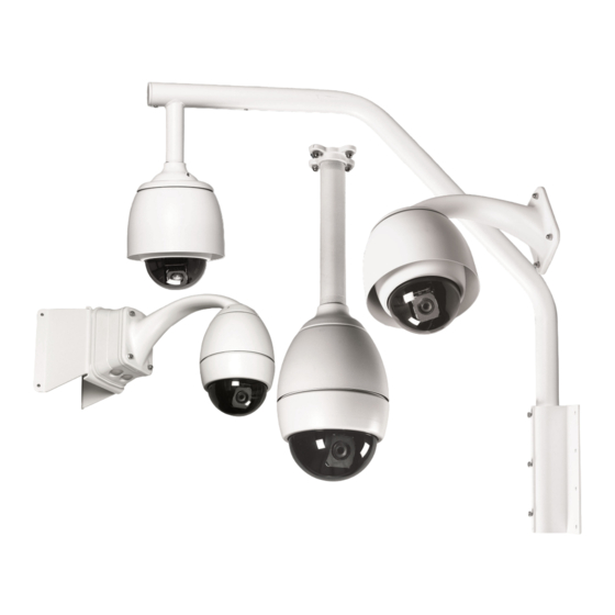
- Page 1 ® ® AutoDome and EnviroDome Indoor Pendant In-ceiling Model Installation Manual Version 5.3 Security you can rely on...
-
Page 2: Important Safeguards
9. Safety Check - Upon completion of servicing or repairs to the unit, ask the service technician to perform safety checks to ensure proper operating condition. © 2005 Bosch Security Systems Page 2 of 36... -
Page 3: Safety Precautions
2. Mechanical Loading - Mounting of the equip- ment in a rack shall be such that a hazardous con- dition is not achieved due to uneven mechanical loading. © 2005 Bosch Security Systems Page 3 of 40... - Page 4 Netzstecker in die Steckdose gesteckt wird. Das Gerät ist jedoch nur betriebsbereit, wenn der Netzschalter (EIN/AUS) auf EIN steht. Wenn das Netzkabel aus der Steckdose gezogen wird, ist die Spannungszuführung zum Gerät vollkommen unterbrochen. © 2005 Bosch Security Systems Page 4 of 40...
-
Page 5: Precauciones De Seguridad
ON. O fio de alimentação destina-se a desligar a in werking als de aan-uitschakelaar aan staat. Het netsnoer is de corrente em todas as unidades. "hoofdschakelaar" voor alle apparatuur. © 2005 Bosch Security Systems Page 5 of 40... - Page 6 Od àczanie zasilania Niezale˝nie od wyposa˝enia w wy àcznik zasilania, pràd do urzàdzenia jest doprowadzany zawsze, gdy przewód zasilania jest pod àczony do êród a zasilania; jednak urzàdzenie dzia a tylko wtedy, gdy wy àcznik zasilania jest © 2005 Bosch Security Systems Page 6 of 40...
-
Page 7: Table Of Contents
FASTADDRESS ........13 SECTION 4 AUTODOME SECURITY ......14 SECTION 5 SECTOR BLANKING AND PRIVACY MASKS . - Page 8 Electrical Code or applicable local codes. Refer to the appropriate installation section. The AutoDome can be mounted to a wall, mast (pole), roof, pipe, or a corner mount once the appropriate mount has been installed. Each mount includes its own mounting instructions.
- Page 9 Pin (1) 24 VAC Hot and Pin (3) Heater (see ALARM INPUT #3 ALARM INPUT #4 APPENDIX A for details). Figure 1C Alarm connector Align the notch on the AutoDome with the notch on the FRONT of the Pendant Arm. © 2005 Bosch Security Systems Page 9 of 40...
- Page 10 Section 1 Lift the AutoDome into the Pendant Arm and twist until the notch on the AutoDome is aligned with the notch on the SIDE of the pendant arm. ALIGN NOTCHES Photo 1I Installed AutoDome ROTATE Photo 1G Align notches 1.10 Tighten the two screws on the top of the...
-
Page 11: In-Ceiling Autodome Installation Instructions
In-ceiling Backbox (LTC 7490), following the instructions provided with that unit. Switch # Function Position Selection Carefully remove the AutoDome from the box. Save all packing material, to be used for setup and transport of the camera and dome. RESERVED RS-485... - Page 12 180 degrees to illustrate red markers. right of either blue label. A straight blade screwdriver will help push the clip in place. MARKERS Photo 2E Align red markers © 2005 Bosch Security Systems Page 12 of 40...
-
Page 13: Fastaddress
Conversely, if FastAddress has been programmed, the thumbwheel switches are ignored. There are two commands used to address the AutoDome via the FastAddress feature: • ON-999-ENTER: All domes that have not already been configured using FastAddress will respond to this command. -
Page 14: Autodome Security
The AutoDome's default password of 0000 <four zeros> allows OFF-90-ENTER to directly unlock the Advanced Menu commands. If the password of 9999 is used, the AutoDome is totally unlocked so that all AutoDome commands can be executed (no OFF-90-ENTER is required to use ADVANCED COMMANDS). -
Page 15: Sector Blanking And Privacy Masks
FIGURE 5B). • FOCUS– deletes the selected mask (and removes the *, signifying that the mask is now unused). • IRIS+ moves the AutoDome so that the highlighted mask is centered on the screen. • IRIS– exits the menu. -
Page 16: Changing The Baud Rate For Rs-232 Or Rs-485 Operation
CHANGING THE COMMUNICATION SETUP FOR RS-232, RS-485 OR Bilinx™ If RS-232 or RS-485 is used to control the AutoDome, the baud rate may be changed via the following steps: View the video from the camera on a monitor. Using an appropriate controller/keyboard, unlock the AutoDome menus using OFF-90-ENTER. -
Page 17: Alarms
Photo 7B Alarm Acknowledged but still active Low Pressure Alarm The pressurized version of the AutoDome has an internal low- pressure sensor that is prewired to Alarm Input # 4. If the inter- nal pressure is lost, the sensor activates the ALARM input, and... - Page 18 Input 1 for a time period of 1 min, and is connected to the Alarm Input of a digital recorder (DVR). When the external contact is closed, the AutoDome will move to SHOT 1, flash the word ALARM on the display, and activate the relay output so the digital recorder starts recording.
-
Page 19: Autotrack
If connected properly, the dome will recognize the AutoTracker, and its features will be visible throughout the AutoDome OSD menus. The only installa- tion setting needed is in the PTZ menu under the heading CAMERA HEIGHT. -
Page 20: Pelco Protocol Mode
Section 9 Software SECTION 9 AutoDome firmware 5.31 or higher must be installed for Pelco pro- tocol mode to operate. Procedures for uploading a new AutoDome PELCO PROTOCOL MODE firmware must be followed to successfully install an upgrade. Description Only a Bosch VP-CFGSFT firmware upload tool (sold... - Page 21 AutoPan and AutoScan 9.10 Preset Tour speeds. Default is 30 degrees/second. The AutoDome can be programmed to execute a Preset Tour with adjustable dwell times. To start a tour, the Pattern 3 Stabilization: (Unlocked) Enables/disables stabilization command must be sent from the Pelco controller by entering mode.
- Page 22 For example, the Reset Camera to Defaults If it is not possible to access the AutoDome’s Setup Menu at the command requires the user to confirm their intent to reset the present baud rate (i.e.
-
Page 23: Maintenance/Component
In instances of high humidity, the EnviroDome may require a replacement desiccant bag. To order, contact Bosch and specify part number 303 3804 003. Service Centers U.S.A.: Phone:... -
Page 24: Troubleshooting Guide
SECTION 11 TROUBLESHOOTING GUIDE Problem Solution NO VIDEO • Ensure that the AutoDome is powered, and all cables are properly connected. • Ensure that the address is properly set. NO CAMERA CONTROL • Ensure that the biphase or RS-232 is connected. - Page 25 Contact Bosch Technical Support for the most current firmware version available. • If the AutoDome is version 5.00 or higher, and the missing menu option requires an upgrade, purchase the Flash Upgrade kit, P/N G3-UPGRADE-5. © 2005 Bosch Security Systems...
-
Page 26: Autodome Locked Commands
AUTODOME LOCKED COMMANDS Access to the AutoDome may be password-protected. See SECTION 4, AutoDome Security for details. To use Locked Commands, first unlock the AutoDome via OFF-90-ENTER. All locked settings, except FastAddress, can then be changed via ON-46-ENTER. Disallow these commands via ON-90-ENTER. -
Page 27: Advanced Menu
ADVANCED MENU. This enhanced software makes programming and customiz- ing the AutoDome easy. All settings are editable via the Main Menu. Press ON-46-ENTER to enter the Main Menu. If no menu is displayed, the system may be locked. - Page 28 LOCKED COMMANDS chart in SECTION 12 (Day/Night models only). LENS SETUP (See FIGURE 13B for LENS SETUP menu hierarchy). Auto Focus – AutoDome automatically focuses on the subject in the center of the screen. The Factory Default setting is SPOT. Choices: Constant .
- Page 29 Restore Defaults – Restores ALL choices for this submenu ONLY, back to the Factory Defaults. Choices: ....Yes, No. © 2005 Bosch Security Systems Page 29 of 40...
- Page 30 Choices: ..OFF*, Normally Open (N.O.), Normally Closed (N.C.). Action – There are three standard choices to determine how the AutoDome will respond when an alarm input is activated, and one additional choice that will appear ONLY when the AutoTracker is being used.
- Page 31 AUTO IRIS – (reduce brightness) LEVEL + (increase brightness) DIGITAL ZOOM Sliding Scale FOCUS 1 (normal) 8 (fast) SPEED *default = 2 RESTORE DEFAULTS * Factory Default Figure 13B Lens Setup © 2005 Bosch Security Systems Page 31 of 40...
- Page 32 RESTORE DEFAULTS * Factory Default Figure 13D Display Setup BAUD RATE *9600 **19200 38400 COMMUNICATION SETUP 57600 BILINX RESTORE DEFAULTS *Factory Default ** AutoTrack uses 19,200 Baud Figure 13E Communication Setup © 2005 Bosch Security Systems Page 32 of 40...
- Page 33 ***A pressurized dome uses Alarm Input 4 for the pressure limit switch Figure 13F Alarm Setup *English Spanish French German LANGUAGE Portuguese SETUP Polish RESTORE DEFAULTS *Factory Default Figure 13G Language Setup © 2005 Bosch Security Systems Page 33 of 40...
-
Page 34: Power Wiring Guide
Power Wiring Guide AutoDome Power Wiring Connections Refer to the following diagram to ensure proper wiring of the AutoDome. If using the ENV-PSU for power, use the THREE WIRE POWER distances identified below. WARNING: Failure to correctly wire the power to the EnviroDome could result in heater malfunction. -
Page 35: Optional Gasket Installation
Appendix B APPENDIX B Gasket Installation (to meet IP66/NEMA 4X, Dust-tight and Powerful Jetting) Install Gasket with Lip on Top. Plate Holds Gasket Securely Insert 4 Screws © 2005 Bosch Security Systems Page 35 of 40... -
Page 36: Autodome User Manual (Insert)
® ® AutoDome and EnviroDome Indoor Pendant In-ceiling Model User Manual Version 5.3 NOTE: Remove this User Manual and supply to user. Security you can rely on © 2005 Bosch Security Systems Page 36 of 40... - Page 37 Saving a scene (Preset) Note: Presets removed from the tour can still be accessed The AutoDome allows up to 99 scenes to be saved and recalled manually). instantly. A saved scene is called a Preset. When a Preset is saved, the position, zoom, and most camera settings are stored.
- Page 38 (see FIGURE 5). To begin recording on A, move the camera to the desired starting point and type ON-100-ENTER. The AutoDome now records all camera activities, until the recording is ended by OFF-100-ENTER. Once A has been recorded, B is available via the ON/OFF-101-ENTER command.
-
Page 39: Autodome User Commands
Switches from color to monochrome (Day/Night models only). Day/Night Menu ON-56-ENTER On-screen menu changes Night Mode setting (On/Off/Auto; Day/Night only). AutoTrack ON/OFF-78-ENTER Allows the operator to turn tracking On and Off (AutoTrack Option only). © 2005 Bosch Security Systems Page 39 of 40... - Page 40 Phone: +65 319 3488 Fax: +1 (585) 223 9180 http://www.boschsecurity.com Fax: +65 319 3499 E-mail: security.sales@us.bosch.com E-mail: sg.securitysystems@bosch.com www.boschsecurity.us http://www.boschsecurity.com © 2005 Bosch Security Systems GmbH 3935 890 43816 05-07 | Updated February 15, 2005 | Data subject to change without notice.
Need help?
Do you have a question about the AutoDome and is the answer not in the manual?
Questions and answers
Wiring diagram for bosch camdome 3.7 surveillance camera
The wiring diagram for the Bosch AutoDome includes the following connections:
1. Power Wiring:
- For EnviroDome models using the ENV-PSU:
- Three-Wire Power:
- Transformer output: 24 VAC @ 30 VA
- Max distances: 18 AWG = 90 ft (27.43 m), 16 AWG = 140 ft (42.67 m), 14 AWG = 225 ft (68.58 m)
- Note: Incorrect wiring may cause heater malfunction.
2. Control Connections:
- 9-Pin Control Connector: Connect and secure using retaining screws.
- 8-Pin Alarm Connector: For alarm inputs or contact output, connect appropriate stripped wires to pin positions labeled GND, A1, A2, etc.
3. Video Connection:
- Connect the BNC cable to the VIDEO (BNC) connector.
4. RS-232 Communication (if AutoTracker option is used):
- Use RXD, TXD, GND connections.
- Max distance: 50 feet.
There is no visual diagram provided, but these are the detailed wiring instructions.
This answer is automatically generated