
Related Manuals for Alto LYNX-MIX USB SERIES


Summary of Contents for Alto LYNX-MIX USB SERIES
- Page 1 USER'S MANUAL LYNX-MIX USB SERIES 12/16/20-CH COMPACT INTEGRATED LIVE SOUND MIXER WITH DIGITAL EFFECTS www.altoproaudio.com Version 1.0 NOV. 2007 English...
- Page 2 IMPORTANT SAFETY INSTRUCTION CAUTION WARNING To reduce the risk of electric shock RISK OF ELECTRIC SHOCK and fire, do not expose this equipment DO NOT OPEN to moisture or rain. TO REDUCE THE RISK OF ELECTRIC SHOCK PLEASE DO NOT REMOVE THE COVER OR Dispose of this product should THE BACK PANEL OF THIS EQUIPMENT.
-
Page 3: Table Of Contents
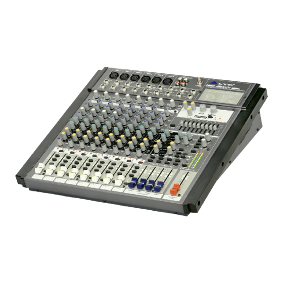
IN THIS MANUAL 1. INTRODUCTION................1 2. FEATURES..................1 3. QUICK START..................5 4. CONTROL ELEMENTS..............7 5. INSTALLATION & CONNECTION............18 6. PRESET LIST..................21 7. BLOCK DIAGRAM................22 8. TECHNICAL SPECIFICATIONS............23 9. WARRANTY..................25 1. INTRODUCTION Thank you for purchasing the LTO L YNX-MIX series compact integrated mixers, which available for 12/16/20 channels. - Page 4 LYNX-MIX124 USB...
- Page 5 LYNX-MIX164 USB...
- Page 6 LYNX-MIX204 USB...
-
Page 7: Quick Start
3. QUICK START This is the fastest way to get something out from your L YNX-MIX USB series , if you have a keyboard and a microphone. a. Plug the microphone into Channel 1 MIC IN. b. Turn down AUX and LEVEL controls on the input channel. c. - Page 8 HOOK LARGE GIG HOOKUP DIAGRAM CD PLAYER WIRELESS WIRELESS MIC 1 MIC 2 MIC 3 MIC 4 MICROPHONE 1 MICROPHONE 2 D/I BOX GUITAR HEADPHONE KEYBOARD BASS DRUM MACHINE ACTIVE SPEAKERS COMPUTER MAIN MIX OUTPUT (BAL/UNBAL) AUX SENDS DIRECT OUTS (BAL/UNBAL) POWER PHANTOM +4dBu...
-
Page 9: Control Elements
4. CONTROL ELEMENTS 1 MONO MIC/LINE Channels Your L YNX-MIX124 USB is equipped with 4 (8 for L YNX-MIX164 USB, 12 for L YNX-MIX204 USB) low-noise microphone preamplifier with optional phantom power, 50 dB of Gain and over 115 dB of S/N ratio. - Page 10 4. CONTROL ELEMENTS instrument, you shall read the LINE ring (+15~-35 dB for mono MIC input, +20~ 20 dB for stereo channels). For optimum operation, you shall set this control in a way that the PEAK LED(16) blinks only occasionally in order to avoid distortion on the input channel.
- Page 11 4. CONTROL ELEMENTS 10 MID This is a peaking filter and it will boost/cut frequencies from 100 Hz to 8 kHz depending on the position of the MID freq control. This control will affect especially upper male and lower female vocal ranges and also the harmonics of most musical instruments.
- Page 12 4. CONTROL ELEMENTS 16 PEAK LED Inside your LYNX-MIX USB mixer, the audio signal is monitored in several different stages and then sent to the PEAK LED. When the LED is red illuminated, it warns you that you are reaching signal saturation and possible distortion, then you should reduce the input level for avoiding distortion.
- Page 13 4. CONTROL ELEMENTS 22 Master AUX SENDS Controls 23 24 20 21 These four controls are used to determine the master AUX SEND levels, which can be varied from - to +15 dB. When the external effect units which has no input gain control were connected to mixer, you can get a further +15 dB gain available from...
- Page 14 4. CONTROL ELEMENTS 27 SUB1-2/SUB3-4/MAIN MIX Buttons These three buttons are configured for AUX RETURN4, they can be regarded as the signal assignment switches. When engaging the SUB1-2, the stereo signal from AUX RETURN4 will be assigned to Subgroup1/2; in the same way, SUB3-4 for Subgroup3/4, MAIN MIX for MAIN MIX buses.
- Page 15 4. CONTROL ELEMENTS after the Level control, otherwise, release the button will output the soloed signal before the Level control. NOTE: The SOLO function can never affect the mix at main recording output, and also can't be affected by channel's MUTE switch. 35 EQ Switch Engage this button to add the stereo graphic EQ to the main mix output circuit.
- Page 16 3. CONTROL ELEMENTS 4. CONTROL ELEMENTS 39 DSP MUTE Switch & PEAK LED This switch is used to activate/deactivate the effect facility. This LED lights up when the input signal is too strong. In case of the digital effect module being muted, this LED also lights up.
- Page 17 3. CONTROL ELEMENTS 4. CONTROL ELEMENTS 45 PHONES Jacks These jacks will be used to send the signal to a pair of headphone or to powered studio monitors. 46 LAMP socket This lovable LAMP is very convenient for your operation, it is located in the top right corner of the front panel, and provides the 12V socket that can drive standard BNC-type lamp.
- Page 18 4. CONTROL ELEMENTS 50 MAIN MIX OUTPUT These stereo outputs are supplied with both the XLR and 1/4" phone jacks and it is controlled by the Main Mix Level. 51 MAIN OUTPUT LEVEL Button This button sets the main mix output level to match the input of the device that you are ready to connect.
- Page 19 3. CONTROL ELEMENTS 4. CONTROL ELEMENTS 59 DFX OUT Jack This 1/4" phone jack is used to output the effect signal that comes from internal DSP module and the signal level can be controlled by the EFFECTS OUT(40) control. 60 FOOTSWITCH Jack This 1/4"...
-
Page 20: Installation And Connection
5. INSTALLATION AND CONNECTION Ok, you have got to this point and you are now in the position to successfully operate your L YNX-MIX USB series. However , we advise you to read the following section carefully to be the real master of your own mix. Not paying enough attention to the input signal level, the routing of the signal and the assignment of the signal will result in unwanted distortion, a corrupted signal or no sound at all. - Page 21 5. INSTALLATION AND CONNECTION Sleeve Tip=Signal Strain Clamp Sleeve=Ground/Screen Use for Mono Line In, Mono 1/4"Jack Plugs 1/4" Mono (TS) Jack Plug Ring=Return Signal Sleeve Ring Strain Clamp Tip=Send Signal Sleeve=Ground/Screen Use for Insert Points 1/4" Stereo (TRS) Jack Plug 2=Hot(+) 2=Hot(+) 1=Ground/Screen...
- Page 22 5. INSTALLATION AND CONNECTION Ring=Return Signal (Connected together) To Channel Insert Sleeve=Ground/Screen Tip=Signal To Tape or FX Input Sleeve=Ground/Screen 'Tapped' Connection Direct Output Lead (Enables the Insert to be used as a Direct Output while maintaining the channel signal flow) To Processor Input Sleeve=Ground/Screen Tip=Send Signal...
-
Page 23: Preset List
6. PRESET LIST Controllable Parameter Preset Description Parameter Variable range Decay time 0.8~1.1s VOCAL1 Simulate a room with small delay time Pre-delay 0~79ms Decay time 0.8~2.5s VOCAL2 Simulate a small space with slight decay time Pre-delay 0~79ms Decay time 3.6~5.4s LARGE HALL Simulate a large acoustic space of the sound Pre-delay... -
Page 24: Block Diagram
7. BLOCK DIAGRAM... -
Page 25: Technical Specification
8. TECHNICAL SPECIFICATION Mono Input Channels Electronically balanced, discrete input configuration Microphone Input Frequency Response 10 Hz to 55 kHz, +/-3 dB Distortion (THD & N) 0.005% at + 4 dBu, 1 kHz Gain Range 0 dB to 50 dB (MIC) SNR (Signal to Noise Ratio) 115 dB Line Input... - Page 26 8. TECHNICAL SPECIFICATION T500 mAL Fuse L YNX- 124 USB L YNX- MIX164 T630 mAL L YNX- MIX204 T750 mAL Main Connection Standard IEC Receptacle Physical Dimension (W D H) L YNX-MIX124 USB 415 mm 400 mm 38/115 mm (16.34" 15.75" 1.49"/4.53") L YNX-MIX164 USB 518 mm 400 mm 38/115 mm (20.39"...
-
Page 27: Warranty
9. WARRANTY 1. WARRANTY REGISTRATION CARD To obtain Warranty Service, the buyer should first fill out and return the enclosed Warranty Registration Card within 10 days of the Purchase Date. All the information presented in this Warranty Registration Card gives the manufacturer a better understanding of the sales status, so as to provide a more effective and efficient after-sales warranty service. - Page 28 NO. 1, Lane 17, Sec. 2, Han Shi West Road, Taichung 40151, Taiwan http://www.altoproaudio.com Tel: 886-4-22313737 email: alto@altoproaudio.com Fax: 886-4-22346757 All rights reserved to ALTO. All features and content might be changed without prior notice. Any photocopy, translation, or reproduction of part of this manual without written permission is forbidden. Copyright 2007 Seikaku Group NF03027-1.0...
Need help?
Do you have a question about the LYNX-MIX USB SERIES and is the answer not in the manual?
Questions and answers