
Related Manuals for Alto L-12


Summary of Contents for Alto L-12
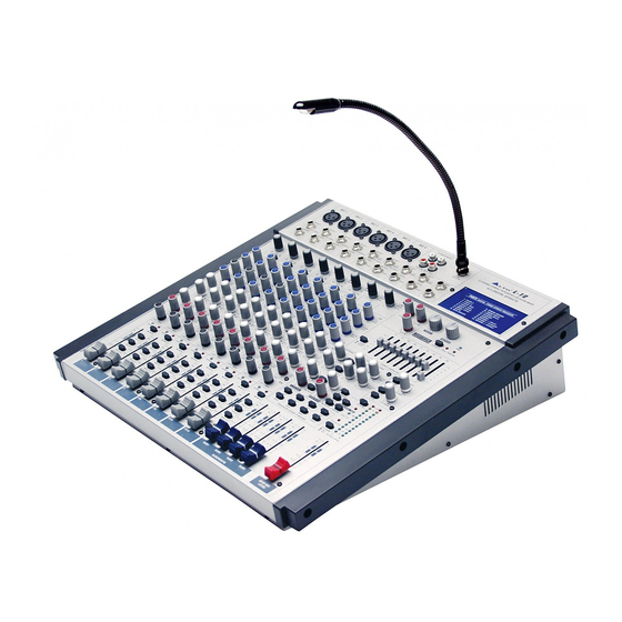
- Page 1 User's Manual 12-CHANNEL COMPACT INTEGRATED L-12 LIVE SOUND MIXER WITH DIGITAL EFFECTS www.altoproaudio.com Version 1.0 August 2003 English...
- Page 2 the recommended fuse type as indicated in this manual. SAFETY RELATED SYMBOLS Do not short-circuit the fuse holder. Before replacing the fuse, make sure that the product is OFF and disconnected CAUTION from the AC outlet. RISK OF ELECTRIC SHOCK DO NOT OPEN Protective Ground This symbol, wherever used, alerts you to the pre-...
- Page 3 Effects, configured with 4 mono and 4 stereo input channels, each channel is equipped with a variety of key features including a warm, natural sounding EQ, Peak LEDs and PAN/BAL control etc.. Besides, the L-12 is equipped with the miraculous 24 bit digital stereo effect processor with 256 presets. Seeing is believing, let's meet the LTO L-12.
-
Page 4: Table Of Contents
TABLE OF CONTENTS 1. INTRODUCTION..............................4 2. FEATURES................................5 3. READY TO START?...............................6 4. CONTROL ELEMENTS............................7 The mono MIC/LINE channels........................8 INPUT LEVEL setting..........................8 Mono Channel INSERT..........................8 LOW-CUT FILTER............................8 STEREO INPUTS............................9 EQUALISER..............................9 AUX SEND..............................10 PAN................................10 SG/PEAK..............................10 4.10 MUTE.................................10 4.11 FADER ..............................11 4.12 ASSIGNMENT Control..........................11 4.13 MASTER SECTION ..........................11 4.14 REAR PANEL DESCRIPTION ........................15 5. -
Page 5: Introduction
/ headphone outputs; subgroups output and small and exquisite modelling. Your L-12 is very easy to operate but we advise you to go through each Section of this Manual carefully. In this way you will get the best out of your L-12. -
Page 6: Features
2. FEATURES The L-12 12 Channel Compact Integrated Mixer with Digital Effects is designed for professional appliance. It will provide the following features: 6 MIC input channels with gold plated XLRs and balanced LINE inputs 4 Stereo input channels with balanced TRS jacks... -
Page 7: Ready To Start
3.3 Before turning on the L-12 you shall connect it to a power amplifier and turn-on the mixer BEFORE the power amplifier. Once you have finished your working session you shall turn the mixer off AFTER the power amplifier. -
Page 8: Control Elements
4. CONTROL ELEMENTS MIC 1 MIC 2 MIC 3 MIC 4 MIC 5 MIC 6 2-TRACK IN/OUT L-12 12 CHANNEL COMPACT INTEGRATED LIVE SOUND MIXER DIGITAL EFFECTS WITH LAMP 12V 0.5A TAPE IN TAPE OUT 24BITs LINE IN 1 LINE IN 2... -
Page 9: The Mono Mic/Line Channels
4. CONTROL ELEMENTS 4.1 The mono MIC/LINE channels These are Channel 1 through Channel 4. You can connect balanced, low im- MIC 1 pedance microphones to the XLR socket. On the 1/4" phone jack you can connect either a microphone or a line level instrument. You shall never connect an unbalanced microphone to the XLR socket if you do not want to damage both the Microphone and the Mixer. -
Page 10: Stereo Inputs
LEFT LEFT (MONO) (MONO) BAL/UNBAL Your L-12 also provides the practical input level setting: LINE IN 8 LINE IN 10 MIC GAIN (the adjustable range is from 0dB to 60dB) RIGHT RIGHT for MIC 5/MIC 6 and LINE GAIN (the adjustable range is from -20dB to +20dB) for LINE IN 9/10 and LINE IN 11/12. -
Page 11: Aux Send
SUB 3-4 MAIN L-R MAIN L-R 4.9 SG/PEAK Inside your L-12 the audio signal is monitored in several different stages and then sent to the SG/PEAK LED. When the LED shows green, it indicates that there present signal on corresponding SOLO SOLO channel;... -
Page 12: Fader
4.10 FADER This Fader will adjust the overall level of this channel and set the amount of signal sent to the Main output or the corresponding SG/PEAK SG/PEAK subgroup output. MUTE MUTE 4.11 ASSIGNMENT Control Each channel provides four push-buttons: SUB1-2, SUB3-4, MAIN SUB 1-2 SUB 1-2 L-R and SOLO. - Page 13 -. Master AUX SENDS The four switches are used to determine the master AUX SEND levels, which can be varied from - to +15dB. AUX SENDS STEREO AUX RETURNS CTRL ROOM SOURCE When the external effect unit connected MAIN MIX to mixer has no input gain control, you can TO AUX SEND1...
- Page 14 -. SUB1-2/3-4/MAIN MIX These three buttons are configured for AUX RETURN4, they can be regarded as the signal assignment switch. When engaging the SUB1-2, the stereo signal from AUX RETURN4 will be assigned to Submix1/2; in the same way, SUB3-4 for Submix3/4, MAIN MIX for MAIN MIX buses. - AUX RETURN SOLO The function of AUX RETURN SOLO is like the channel SOLO button.
- Page 15 AUX SEND1 and AUX SEND2. The adjustable range can be varied from - to +15dB. POWER LED The LED indicates when the Power is on in your L-12. PHANTOM LED This LED indicates when the Phantom Power is switched on.
-
Page 16: Rear Panel Description
- AC INLET WITH FUSE HOLDER Use it to connect your L-12 to the Main AC with the supplied AC cord. Please check the Voltage available AC INPUT in your Country and how the Voltage for your L-12... - Page 17 MAIN MIX OUTPUT (BAL/UNBAL) MAIN INSERT +4dBu -30dBu MAIN TIP SEND OUTPUT MONO CTRL OUT DFX OUT RING RETURN LEVEL (BAL/UNBAL) FOOT SWITCH - MAIN MIX OUTPUT This stereo output is supplied with both the XLR and 1/4" phone sockets and it is controlled by the Main Mix Level.
- Page 18 DIRECT OUTS (BAL/UNBAL) AUX SENDS AUX RETURNS SUBGROUPS OUT SUBGROUPS INSERT - AUX SENDS These 1/4" phone sockets are used to send out the signal from the AUX Bus to external devices such as effects. - AUX RETURNS Use these stereo 1/4" phone sockets to return the sound of an effect unit to the Main Mix. You can also use them as an extra auxiliary input.
-
Page 19: Installation And Connection
5. INSTALLATION AND CONNECTION Ok, you have got to this point and you are now in the position to successfully operate your L-12. However, we advise you to read carefully the following section to be the real Master of your own Mix. Not paying attention enough to the input signal level, to the routing of the signal and the assignment of the signal will result in unwanted distortion, a corrupted signal or no sound at all. - Page 20 5.1 SOME FINAL TIPS ON WIRING CONFIGURATION You can connect unbalanced equipment to balanced inputs and outputs. Simply follow these schematics. Ring=Right Signal Sleeve Ring Strain Clamp Tip=Left Signal Sleeve=Ground/Screen Use for Headphone 1/4" Stereo (TRS) Jack Plug Sleeve Tip=Signal Strain Clamp Sleeve=Ground/Screen Use for Mono Line In, Mono 1/4"Jack Plugs...
- Page 21 Ring=Return Signal (Connected together) To Channel Insert Sleeve=Ground/Screen Tip=Signal To Tape or FX Input Sleeve=Ground/Screen 'Tapped' Connection Direct Output Lead (Enables the Insert to be used as a Direct Output while maintaining the channel signal flow) To Processor Input Sleeve=Ground/Screen Tip=Send Signal To Channel Insert Ring=Return Signal...
-
Page 22: Preset List
6. PRESET LIST 01. VOCAL1 Pre-delay Rev. Type Hi Damp Rev Time Room Size 1.00 Hall Tape 1.00 Spring 4.50 3.60 Plate Spring 1.20 Hall 3.60 Plate 1.50 Plate Spring 2.40 Tape 0.90 1.50 Plate 1.00 Hall Spring 1.00 Tape 2.10 4.50 Plate... - Page 23 4.00 -0.96 4.00 -12.00 4.00 -0.96 4.00 -12.00 3.60 -0.96 3.60 -12.00 3.60 -0.96 3.60 -12.00 04. SMALL HALL Pre-delay Hi Damp Rev Time Room Size Rev level 2.90 -0.96 2.90 -12.00 2.90 -0.96 2.90 -12.00 2.10 -0.96 2.10 -12.00 2.10 -0.96 2.10...
- Page 24 06. SMALL ROOM Pre-delay Hi Damp Rev Time Room Size Rev level 2.10 -0.96 2.10 -12.00 2.10 -0.96 2.10 -12.00 1.50 -0.96 1.50 -12.00 1.50 -0.96 1.50 -12.00 1.00 -0.96 1.00 -12.00 1.00 -0.96 1.00 -12.00 0.70 -0.96 0.70 -12.00 0.70 -0.96 0.70...
- Page 25 3.60 -0.96 3.60 -12.00 2.90 -0.96 2.90 -12.00 2.10 -0.96 2.10 -12.00 1.30 -0.96 1.30 -12.00 09. SPRING REVERB Pre-delay Hi Damp Rev Time Rev level Room Size -0.96 -12.00 4.50 -0.96 4.50 -12.00 -0.96 -12.00 3.60 -0.96 3.60 -12.00 2.90 -0.96 2.90...
- Page 26 11. STEREO DELAY Delay Right Delay Left F.B. Right F.B. 12. FLANGER Mod. Freq Pitch. Depth Left F.B. Right F.B. 2.79 2.52 2.33 2.25 2.10 1.99 1.75 1.61 1.34 1.22 1.00 0.80 0.65 0.54 0.42 0.16 13. CHORUS Mod. Freq. Pitch.
- Page 27 2.33 -3(0) 1.99 -3(0) 1.70 -3(0) 1.35 -2(0) 1.00 -2(0) 0.50 -2(0) 14. REVERB+DELAY Rev Time Room Size Left Delay Right Delay Left F.B. Right F.B. Rev level 2.90 2.90 2.90 2.90 2.40 2.40 2.40 2.40 2.10 2.10 1.50 1.50 1.50 1.50 1.00...
- Page 28 16. REVERB+CHORUS Rev Time Room Size Mod. Freq. Pitch. Depth Left F.B. Rev level 2.90 4.74 2.90 4.12 2.90 3.67 2.90 3.02 2.90 2.63 2.90 1.99 2.90 1.35 2.90 0.50 1.50 4.74 1.50 4.12 1.50 3.67 1.50 3.02 1.50 2.63 1.50 1.99 1.00...
-
Page 29: System Block Diagrams
7. SYSTEM BLOCK DIAGRAMS CTRL/R CTRL/R CTRL/L CTRL/L SEND SEND LOGIC LOGIC SOLO(PFL) SOLO(PFL) AFL-R AFL-R AFL-L AFL-L AUX4 AUX4 AUX3 AUX3 AUX2 AUX2 AUX1 AUX1 SUB4 SUB4 SUB3 SUB3 SUB2 SUB2 SUB1 SUB1 RIGHT-BUS RIGHT-BUS LEFT-BUS LEFT-BUS... -
Page 30: Technical Specification
8. TECHNICAL SPECIFICATION Mono input channels Microphone input electronically balanced, discrete input configuration Frequency response 10Hz to 55kHz, + Distortion (THD & N) 0.005% at 4dBu, 1kHz Gain range 0dB to 60dB (MIC) SNR (Signal to Noise Ratio) 115dB Line input electronically balanced Frequency response 10Hz to 55kHz,... - Page 31 Power supply Main voltage USA/Canada 100 120V~, 60Hz Europe 210 240V~, 50Hz U.K./Australia 240V~, 50Hz Power Consumption 60 watts Fuse 100 120V~ : T630mAL 210 240V~ : T400mAL Standard IEC receptacle Main connection Physical Dimension (W D H) 495mm 415mm 39/117mm (14.29"...
-
Page 32: Warranty
9. WARRANTY 1. WARRANTY REGISTRATION CARD To obtain Warranty Service, the buyer should first fill out and return the enclosed Warranty Registration Card within 10 days of the Purchase Date. All the information presented in this Warranty Registration Card gives the manufacturer a better understanding of the sales status, so as to purport a more effective and efficient after-sales warranty service. - Page 33 Tel: 886-4-22313737 email: info@altomobile.com Fax: 886-4-22346757 All rights reserved to ALTO Mobile. Due to continued development in response to customer feedback, product features, specifications and/or internal/external design may be changed without prior notice. No photocopying, translation or reproduction of any part of this user manual is allowed without prior written permission.Copyright...
Need help?
Do you have a question about the L-12 and is the answer not in the manual?
Questions and answers