
Related Manuals for Alto LYNX-MIX 124UM


Summary of Contents for Alto LYNX-MIX 124UM
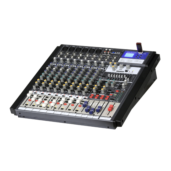
- Page 1 USER'S MANUAL LYNX-MIX 124UM 12-CH COMPACT INTEGRATED RECORDING/LIVE SOUND MIXER WITH DIGITAL EFFECTS AND USB PLAYER www.altoproaudio.com Version 1.2 DEC. 2009 English...
- Page 2 IMPORTANT SAFETY INSTRUCTION CAUTION WARNING To reduce the risk of electric shock RISK OF ELECTRIC SHOCK and fire, do not expose this equipment DO NOT OPEN to moisture or rain. TO REDUCE THE RISK OF ELECTRIC SHOCK PLEASE DO NOT REMOVE THE COVER OR Dispose of this product should THE BACK PANEL OF THIS EQUIPMENT.
-
Page 3: Table Of Contents
IN THIS MANUAL 1. INTRODUCTION...................1 2. FEATURES..................1 3. QUICK START..................4 4. CONTROL ELEMENTS.................5 5. INSTALLATION & CONNECTION............16 6. OPERATION INSTRUCTION FOR MP3..........19 7. PRESET LIST..................22 8. BLOCK DIAGRAM................23 9. TECHNICAL SPECIFICATIONS............24 10. WARRANTY..................25 1. INTRODUCTION Thank you for purchasing the 12-inputs LTO L YNX-MIX 124UM compact mixer. - Page 5 HOOK LARGE GIG HOOKUP DIAGRAM WIRELESS CD PLAYER MIC 1 MIC 2 MICROPHONE 2 USB Driver WIRELESS MICROPHONE 1 D/I BOX GUITAR HEADPHONE KEYBOARD BASS DRUM MACHINE ACTIVE STAGE MONITORS COMPUTER MAIN MIX OUTPUT (BAL/UNBAL) AUX SENDS POWER PHANTOM +4dBu -30dBu MAIN MAIN...
-
Page 6: Quick Start
3. QUICK START This is the fastest way to get something out from your L YNX-MIX124UM, if you have a keyboard and a microphone. a. Plug the microphone into Channel 1 MIC IN. b. Turn down AUX and LEVEL controls on the input channel. c. -
Page 7: Control Elements
4. CONTROL ELEMENTS 1 MONO MIC/LINE Channels Your L YNX-MIX 124UM is equipped with 4 low-noise microphone preamplifier with optional phantom power, 50 dB of Gain and over 115 dB of S/N ratio. You can connect almost any type of microphone. Dynamic microphones do not need phantom power. - Page 8 4. CONTROL ELEMENTS 5 LINE GAIN When you use a line level instrument, you shall read the ring (-20~+20 dB). For optimum operation, you shall set this control in a way that the PEAK LED (17) signal peaks only, thus avoiding input channel distortion.
- Page 9 4. CONTROL ELEMENTS 11 MID This is a peaking filter and it will boost/cut frequencies from 100 Hz to 8 kHz depending on the position of the MID freq control. Setting the frequency control on lower frequencies, this control will affect the range of fundamental frequencies of most instruments, including human voices, as well as some harmonics when set to higher frequencies.
- Page 10 4. CONTROL ELEMENTS 17 PEAK LED Inside your LYNX-MIX 124UM mixer, the audio signal is treated in several different stages and then sent to the PEAK LED. When the LED is red illuminated, it warns you that you are reaching signal saturation and possible distortion, In order to avoid distortion you should reduce the GAIN, EQ, or LEVEL settings.
- Page 11 4. CONTROL ELEMENTS 23 Master AUX SENDS Controls These four controls are used to determine the master AUX SEND levels, which can be varied from - to +15 dB. Connecting to your mixer an external effect units with no input gain control , you can get a further +15 dB gain available from these Aux Send outputs.
- Page 12 4. CONTROL ELEMENTS 28 SUB1-2/SUB3-4/MAIN MIX Buttons These three buttons are configured for AUX RETURN4, they can be regarded as the signal assignment switches. When engaging the SUB1-2, the stereo signal from AUX RETURN4 will be assigned to Subgroup1/2; in the same way, pressing SUB3-4 the signal will be assigned to Subgroup3/4, and pressing MAIN MIX it will be assigned to MAIN MIX buses.
- Page 13 When all the faders are in cent r position, the output of the equalizer is flat response. DSP SECTION There is a powerful 24-bit/256 preset multi-effects included in your LYNX-MIX 124UM. Effects include reverbs, chorus, flanger, delay and combinations of the above. 38 PRESETS Adjust this knob to select the effect you wish to perform.
- Page 14 3. CONTROL ELEMENTS 4. CONTROL ELEMENTS 40 DSP MUTE Switch & PEAK LED This switch is used to activate/deactivate the effect facility. This LED lights up when the input signal is too strong. This LED is lit also when the digital effect module has been muted.
- Page 15 3. CONTROL ELEMENTS 4. CONTROL ELEMENTS 45 2-TRACK IN/OUT - TAPE IN Use the Tape input to listen the playback signal from a Tape Recorder or DAT. - TAPE OUT These RCA jacks will route the main mix signal to a tape recorder.
- Page 16 4. CONTROL ELEMENTS 49 AC Inlet with FUSE Holder Use it to connect your L YNX- MIX 124UM mixer to the main AC with the supplied AC cord. Please check the voltage available in your country and how the voltage for your L YNX- MIX 124UM mixer is configured before attempting to connect your L YNX-...
- Page 17 3. CONTROL ELEMENTS 4. CONTROL ELEMENTS 58 CTRL OUT Jacks These 1/4" phone jacks will be used to send the Control Room signal to the studio monitor speakers or a second set of PA. 59 DFX OUT Jack This 1/4" phone jack is used to output the effect signal generated from internal DSP module.
-
Page 18: Installation And Connection
5. INSTALLATION AND CONNECTION Ok, you have got to this point and you are now in the position to successfully operate your L YNX-MIX 124UM. However, we advise you to read the following section carefully to be the real master of your own mix. Not paying enough attention to the input signal level, the routing of the signal and the assignment of the signal will result in unwanted distortion, a corrupted signal or no sound at all. - Page 19 5. INSTALLATION AND CONNECTION Ring=Right Signal Sleeve Ring Strain Clamp Tip=Left Signal Sleeve=Ground/Screen Use for Headphone 1/4" Stereo (TRS) Jack Plug Sleeve Tip=Signal Strain Clamp Sleeve=Ground/Screen Use for Mono Line In, Mono 1/4"Jack Plugs 1/4" Mono (TS) Jack Plug Ring=Return Signal Sleeve Ring Strain Clamp...
- Page 20 5. INSTALLATION AND CONNECTION Ring=Return Signal (Connected together) To Channel Insert Sleeve=Ground/Screen Tip=Signal To Tape or FX Input Sleeve=Ground/Screen 'Tapped' Connection Direct Output Lead (Enables the Insert to be used as a Direct Output while maintaining the channel signal flow) To Processor Input Sleeve=Ground/Screen Tip=Send Signal...
-
Page 21: Operation Instruction For Mp3
6. The Operation Instructions for Mp3 1. Note a. USB Memory Format: FAT16, FAT32 b. Playing Type: Only support MP3 playing c. It can read up to 7 rank folders of your USB player. 2. Operation Instruction 2.1 when no USB KEY is inserted, your L YNX 124UM display will show the following screen: INSERT USB KEY Fig 1... - Page 22 6. The Operation Instructions for Mp3 b. After opening the folder, the display will show a screen like the following one. This screen displays MP3 file list, and scrolling the list using "<<" or ">>" keys you can choose the desired song. Pressing the "Play" key, the selected song playback will start.
- Page 23 6. The Operation Instructions for Mp3 classic music [ . ] Plena pop Plena pop 02.mp [ . ] Plena pop 03.mp Fig 6 c. The screen will display the following screen. Pressing the "<<" or ">>" keys you can select the starting song, then pressing the "Play" key the selected song playback will start.
-
Page 24: Preset List
7. PRESET LIST Controllable Parameter Preset Description Parameter Variable range Decay time 0.8~1.1s VOCAL1 Simulate a room with small delay time Pre-delay 0~79ms Decay time 0.8~2.5s VOCAL2 Simulate a small space with slight decay time Pre-delay 0~79ms Decay time 3.6~5.4s LARGE HALL Simulate a large acoustic space of the sound Pre-delay... -
Page 25: Block Diagram
8. BLOCK DIAGRAM... -
Page 26: Technical Specification
9. TECHNICAL SPECIFICATION Mono Input Channels Electronically balanced, discrete input configuration Microphone Input Frequency Response 10 Hz to 55 kHz, +/-3 dB Distortion (THD & N) 0.005% at + 4 dBu, 1 kHz Gain Range 0 dB to 50 dB (MIC) SNR (Signal to Noise Ratio) 115 dB Line Input... -
Page 27: Warranty
10. WARRANTY 1. WARRANTY REGISTRATION CARD To obtain Warranty Service, the buyer should first fill out and return the enclosed Warranty Registration Card within 10 days of the Purchase Date. All the information presented in this Warranty Registration Card gives the manufacturer a better understanding of the sales status, so as to provide a more effective and efficient after-sales warranty service. - Page 28 NO. 1, Lane 17, Sec. 2, Han Shi West Road, Taichung 40151, Taiwan www.altoproaudio.com Tel: 886-4-22313737 email: info@altoproaudio.com Fax: 886-4-22346757 All rights reserved to ALTO. All features and content might be changed without prior notice. Any photocopy, translation, or reproduction of part of this manual without written permission is forbidden. Copyright 2008 Seikaku Group NF03198-1.2...
Need help?
Do you have a question about the LYNX-MIX 124UM and is the answer not in the manual?
Questions and answers