
Related Manuals for Alto L-16


Summary of Contents for Alto L-16
- Page 1 User's Manual 16-CHANNEL COMPACT INTEGRATED L-16 LIVE SOUND MIXER WITH DIGITAL EFFECTS www.altoproaudio.com Version 1.0 September 2003 English...
- Page 2 SAFETY RELATED SYMBOLS CAUTION RISK OF ELECTRIC SHOCK DO NOT OPEN This symbol, wherever used, alerts you to the pre- sence of un-insulated and dangerous voltages with- in the product enclosure. These are voltages that may be sufficient to constitute the risk of electric shock or death.
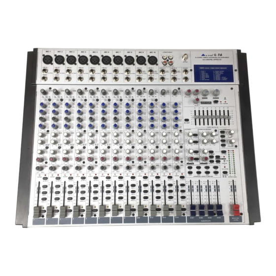
- Page 3 Effects, configured with 8 mono and 4 stereo input channels, each channel is equipped with a variety of key features including a warm, natural sounding EQ, Peak LEDs and PAN/BAL control etc.. Besides, the L-16 is equipped with the miraculous 24 bit digital stereo effect processor with 256 presets. Seeing is believing, let's meet the LTO L-16.
-
Page 4: Table Of Contents
1. INTRODUCTION...4 2. FEATURES...5 3. READY TO START?...6 4. CONTROL ELEMENTS...7 The MONO MIC/LINE Channels...8 INPUT LEVEL Setting...8 MONO Channel INSERT...8 LOW-CUT FILTER...8 STEREO INPUTS...9 EQUALISER...9 AUX SENDS Level Control...10 PAN/BAL Control...10 SG/PEAK LED...10 4.10 MUTE Switch...10 4.11 FADER ...11 4.12 ASSIGNMENT Control... -
Page 5: Introduction
/ headphone outputs and subgroups output. Your L-16 is very easy to operate but we advise you to go through each Section of this Manual carefully. In this way you will get the best out of your L-16. -
Page 6: Features
The L-16 16 Channel Compact Integrated Mixer with Digital Effects is designed for professional appliance. It will provide the following features: 10 MIC input channels with gold plated XLRs and balanced LINE inputs 4 Stereo input channels with balanced TRS jacks... -
Page 7: Ready To Start
3.3 Before turning on the L-16 you shall connect it to a power amplifier and turn-on the mixer BEFORE the power amplifier. Once you have finished your working session you shall turn the mixer off AFTER the power amplifier. -
Page 8: Control Elements
4. CONTROL ELEMENTS 1 1 1 1 1 1 1 1 1 1... -
Page 9: The Mono Mic/Line Channels
4.1 The MONO MIC/LINE Channels These are Channel 1 through Channel 8. You can connect balanced, low im- pedance microphones to the XLR socket. On the 1/4" phone jack you can connect either a microphone or a line level instrument. You shall never connect an unbalanced microphone to the XLR socket if you do not want to damage both the Microphone and the Mixer. -
Page 10: Stereo Inputs
If you connect only the left jack, the input will operate in mono mode. Your L-16 also provides the practical input level setting: MIC GAIN (the adjustable range is from 0dB to 60dB) for MIC 9/MIC 10 and LINE GAIN (the adjustable range is from -20dB to +20dB) for LINE IN 13/14 and LINE IN 15/16. -
Page 11: Aux Sends Level Control
1-2 and SUB 3-4 if the SUB 1-2 or SUB 3-4 push-button is pressed. 4.9 SG/PEAK LED Inside your L-16 the audio signal is monitored in several different stages and then sent to the SG/PEAK LED. When the LED shows green, it indicates that there present signal on corresponding channel;... -
Page 12: Fader
4.10 FADER This Fader will adjust the overall level of this channel and set the amount of signal sent to the Main output or the corresponding subgroup output. 4.11 ASSIGNMENT Control Each channel provides four push-buttons: SUB1-2, SUB3-4, MAIN L-R and SOLO. Pressing the SOLO button, the corresponding SOLO LED will ill- uminate and the SOLO signal will replace other signals sent to the headphone/CONTROL ROOM and meters. - Page 13 - Master AUX SENDS The four switches are used to determine the master AUX SEND levels, which can be varied from - to +15dB. When the external effect unit connected to mixer has no input gain control, you can get a further +15dB gain available form these AUX SEND outputs.
- Page 14 - SUB1-2/SUB3-4/MAIN MIX These three buttons are configured for AUX RETURN4, they can be regarded as the signal assignment switches. Engage the SUB1-2 button to assign the stereo signal from AUX RETURN4 to Submix1/2; in the same way, SUB3-4 for Submix3/4, MAIN MIX for MAIN MIX buses. - AUX RETURN SOLO The function of AUX RETURN SOLO is like the channel SOLO button.
- Page 15 - 24 BIT DIGITAL EFFECTS PRESETS Adjust this knob to select the right effect you wish to perform. There are total 16 options for you: several kinds of reverb, mono and stereo delay, effects with modulation, and versatile two-effect combination. This LED indicates when the P hantom Power is switched on8- EQ switch41 These AUX1 and MUTE switch35...
-
Page 16: Rear Panel Description
Phantom Power is on already. - AC inlet with fuse holder Use it to connect your L-16 to the Main AC with the supplied AC cord. Please check the Voltage available in your Country and how the Voltage for your L-16 is configured before attempting to connect your L-16 to the Main AC. - Page 17 MAIN MIX OUTPUT (BAL/UNBAL) - MAIN MIX OUTPUT This stereo output is supplied with both the XLR and 1/4" phone sockets and it is controlled by the Main Mix Level. - MAIN OUTPUT LEVEL This button sets the main mix output level to match the input of the device that you are ready to connect. Engage this button to reduce the output level from MAIN MIX OUTPUT by 30dBu, it used to match the semipro -30dBu device, on the contrary, to match the professional +4dBu device.
- Page 18 - AUX SENDS These 1/4" phone sockets are used to send out the signal from the AUX Bus to external devices such as effects. - AUX RETURNS Use these stereo 1/4" phone sockets to return the sound of an effect unit to the Main Mix. You can also use them as an extra auxiliary input.
- Page 19 - DIRECT OUTS Each MONO MIC/LINE channel (CH1-CH8) is equipped the 1/4" phone socket for direct output. These jacks are used to send the signal from the channel path to external device for recording function etc.. - SUBGROUPS OUT These 1/4" phone sockets are used to connect the inputs of deck or available for a complicated PA live sound system.
-
Page 20: Installation And Connection
Ok, you have got to this point and you are now in the position to successfully operate your L-16. However, we advise you to read carefully the following section to be the real Master of your own Mix. Not paying attention enough to the input signal level, to the routing of the signal and the assignment of the signal will result in unwanted distortion, a corrupted signal or no sound at all. - Page 21 You can connect unbalanced equipment to balanced inputs and outputs. Simply follow these schematics. Strain Clamp Strain Clamp Strain Clamp 2=Hot(+) 3=Cold(-) Use for Balanced Mic Inputs (For unbalanced use, connect pin 1 to 3) 3-pin XLR Male Plug (seen from soldering side) Ring=Right Signal Sleeve Ring...
- Page 22 Ring=Return Signal (Connected together) Sleeve=Ground/Screen Tip=Signal Sleeve=Ground/Screen 'Tapped' Connection Direct Output Lead (Enables the Insert to be used as a Direct Output while maintaining the channel signal flow) Sleeve=Ground/Screen Ring Sleeve -Stereo lead for insert Connection (To be used when the processor does not employ a single jack connection for the In/Out Connections) To Channel Insert To Tape or FX Input...
-
Page 23: Preset List
01. VOCAL1 Pre-delay 02. VOCAL2 Pre-delay 03. LARGE HALL Pre-delay Rev Time Room Size 1.00 1.00 4.50 3.60 1.20 3.60 1.50 2.40 0.90 1.50 1.00 1.00 2.10 4.50 1.70 Rev Time Room Size 1.00 0.80 3.60 1.20 3.60 4.50 1.00 1.00 1.70 4.50... - Page 24 04. SMALL HALL Pre-delay 05. LARGE ROOM Pre-delay 4.00 4.00 4.00 4.00 3.60 3.60 3.60 3.60 Rev Time Room Size 2.90 2.90 2.90 2.90 2.10 2.10 2.10 2.10 1.50 1.50 1.50 1.50 1.00 1.00 1.00 1.00 Rev Time Room Size 4.50 4.50 4.50...
- Page 25 Pre-delay 07. PLATE Pre-delay 08. TAPE REVERB Pre-delay Rev Time Room Size 2.10 2.10 2.10 2.10 1.50 1.50 1.50 1.50 1.00 1.00 1.00 1.00 0.70 0.70 0.70 0.70 Rev Time Room Size 6.10 5.40 4.50 4.00 3.60 2.90 2.40 2.10 1.70 1.50 1.30...
- Page 26 09. SPRING REVERB Pre-delay 10. MONO DELAY Delay 3.60 3.60 2.90 2.90 2.10 2.10 1.30 1.30 Rev Time Room Size 4.50 4.50 3.60 3.60 2.90 2.90 2.40 2.40 1.70 1.70 1.30 1.30 F.B. -0.96 -12.00 -0.96 -12.00 -0.96 -12.00 -0.96 -12.00 Hi Damp Rev level...
- Page 27 Delay 12. FLANGER Mod. Freq 2.79 2.52 2.33 2.25 2.10 1.99 1.75 1.61 1.34 1.22 1.00 0.80 0.65 0.54 0.42 0.16 13. CHORUS Mod. Freq. 5.00 4.74 4.39 4.12 3.90 3.67 3.32 3.02 2.87 2.63 Right Delay Left F.B. Pitch. Depth Left F.B.
- Page 28 2.33 1.99 1.70 1.35 1.00 0.50 14. REVERB+DELAY Rev Time 2.90 2.90 2.90 2.90 2.40 2.40 2.40 2.40 2.10 2.10 1.50 1.50 1.50 1.50 1.00 1.00 15. REVERB+FLANGER Rev Time 2.90 2.90 2.90 2.90 2.90 2.90 2.90 2.90 1.50 1.50 1.50 1.50 1.50...
- Page 29 Rev Time Room Size 2.90 2.90 2.90 2.90 2.90 2.90 2.90 2.90 1.50 1.50 1.50 1.50 1.50 1.50 1.00 1.00 Mod. Freq. Pitch. Depth 4.74 4.12 3.67 3.02 2.63 1.99 1.35 0.50 4.74 4.12 3.67 3.02 2.63 1.99 1.35 0.50 Left F.B.
-
Page 30: System Block Diagrams
SEND SOLO(PFL) AFL-R AFL-L AUX2 AUX1 RIGHT-BUS LEFT-BUS SEND SOLO(PFL) AFL-R AFL-L AUX2 AUX1 RIGHT-BUS LEFT-BUS... -
Page 31: Technical Specification
Mono input channels Microphone input Frequency response Distortion (THD & N) Gain range SNR (Signal to Noise Ratio) Line input Frequency response Distortion (THD & N) Sensitivity range Stereo input channels Line input Frequency response Distortion (THD & N) Impedances Microphone input Channel Insert return All other inputs... - Page 32 Power supply Main voltage Power Consumption Fuse Main connection Physical Dimension (W D H) Net weight USA/Canada 100 120V~, 60Hz Europe 210 240V~, 50Hz U.K./Australia 240V~, 50Hz 65 watts 100 120V~ : T800mAL 210 240V~ : T500mAL Standard IEC receptacle 495mm 495mm 38/117mm (19.48"...
-
Page 33: Warranty
1. WARRANTY REGISTRATION CARD To obtain Warranty Service, the buyer should first fill out and return the enclosed Warranty Registration Card within 10 days of the Purchase Date. All the information presented in this Warranty Registration Card gives the manufacturer a better understanding of the sales status, so as to purport a more effective and efficient after-sales warranty service. - Page 34 SEIKAKU TECHNICAL GROUP LIMITED No. 1, Lane 17, Sec. 2, Han Shi W. Road, Taichung, 401 Taiwan http://www.altomobile.com Tel: 886-4-22313737 email: info@altomobile.com Fax: 886-4-22346757 All rights reserved to ALTO Mobile. Due to continued development in response to customer feedback, product features, specifications and/or internal/external design may be changed without prior notice.
Need help?
Do you have a question about the L-16 and is the answer not in the manual?
Questions and answers