Sign In
Upload
Download
Table of Contents
Contents
Add to my manuals
Delete from my manuals
Share
URL of this page:
HTML Link:
Bookmark this page
Add
Manual will be automatically added to "My Manuals"
Print this page
×
Bookmark added
×
Added to my manuals
Manuals
Brands
Alto Manuals
Music Mixer
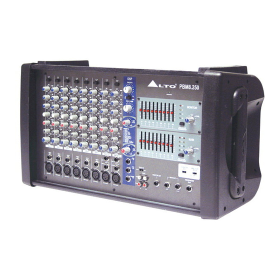
PBM8.250
User manual
Alto PBM8.250 User Manual
8-channel stereo powered mixer with dsp
Hide thumbs
Also See for PBM8.250
:
Service manual
(51 pages)
1
2
3
Table Of Contents
4
5
6
7
8
9
10
11
12
13
14
15
16
17
18
19
20
21
22
23
24
25
26
27
28
29
30
page
of
30
Go
/
30
Contents
Table of Contents
Bookmarks
Table of Contents
Table of Contents
1 Introduction
2 Features
3 Quick Start
4 Control Elements
MONO/STEREO Input Channel Section
MASTER SECTION Control
MASTER SECTION INPUT and OUTPUT Jacks
DSP Section
Rear Panel
5 Preset List
6 Installation and Connection
Audio Connections
Speaker Connections
Possible System Connection Mode for Live Sound Application
7 Technical Specification
8 Warranty
Advertisement
Quick Links
1
Introduction
2
Features
3
Quick Start
4
Master Section Input and Output Jacks
5
Audio Connections
6
Installation and Connection
7
Speaker Connections
8
Technical Specification
Download this manual
See also:
Service Manual
User's Manual
PBM8.250/
8-channel
PBM8.500
Stereo Powered Mixer with DSP
R
LTO
www.altoproaudio.com
Version 1.2 August 2004
English
Table of
Contents
Previous
Page
Next
Page
1
2
3
4
5
Advertisement
Table of Contents
Need help?
Do you have a question about the PBM8.250 and is the answer not in the manual?
Ask a question
Questions and answers
Related Manuals for Alto PBM8.250
Mixer Alto PBM 8.250 Service Manual
Powered mixer (51 pages)
Music Mixer ALTO PBM8.500 User Manual
8-channel stereo powered mixer with dsp (30 pages)
Music Mixer Alto PBM8.350 UM User Manual
8-channel stereo powered mixer with dsp and mp3 player (14 pages)
Music Mixer Alto PBM4 SISTEMA User Manual
Portable pa system (16 pages)
Music Mixer Alto PBM4 Owner's Manual
Compact powered mixer (18 pages)
Music Mixer Alto PBM8.250 MKII Service Manual
(36 pages)
Music Mixer Alto PBM8.500 MKII Service Manual
(36 pages)
Music Mixer Alto PBM4D User Manual
(18 pages)
Music Mixer Alto PM-8 DRAGONFLY User Manual
8-channel mixing console with digital effects (24 pages)
Music Mixer Alto PM-12 DRAGONFLY User Manual
12-channel mixing console with digital effects (36 pages)
Music Mixer Alto Dragonfly PM-12 Service Manual
(111 pages)
Music Mixer Alto L-16 User Manual
16-channel compact integrated live sound mixer with digital effects (34 pages)
Music Mixer Alto GHIBLI 16 User Manual
16-channel mixing console/with digital effects (19 pages)
Music Mixer ALTO L-8 User Manual
8-channel with digital effects (30 pages)
Music Mixer Alto AMX-180 User Manual
18-channel, with digital effects (30 pages)
Music Mixer Alto ZMX 164 FX USB Quick Start Manual
(37 pages)
This manual is also suitable for:
Pbm8.500
Table of Contents
Save PDF
Print
Rename the bookmark
Delete bookmark?
Delete from my manuals?
Login
Sign In
OR
Sign in with Facebook
Sign in with Google
Upload manual
Upload from disk
Upload from URL


Need help?
Do you have a question about the PBM8.250 and is the answer not in the manual?
Questions and answers