Table of Contents
Advertisement
R
LTO
USER'S MANUAL
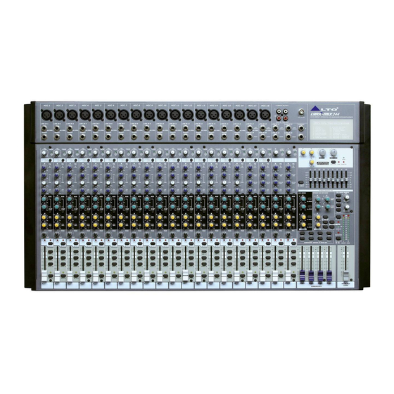
LYNX-MIX244
24-CH COMPACT INTEGRATED
LIVE SOUND MIXER WITH DIGITAL EFFECTS
SEIKAKU TECHNICAL GROUP LIMITED
NO. 1, Lane 17, Sec. 2, Han Shi West Road, Taichung 40151, Taiwan
http://www.altoproaudio.com Tel: 886-4-22313737
email: alto@altoproaudio.com Fax: 886-4-22346757
All rights reserved to ALTO. All features and content might be changed
www.altoproaudio.com
without prior notice. Any photocopy, translation, or reproduction of part of this
Version 1.0 MAR. 2008
c
manual without written permission is forbidden. Copyright
2008 Seikaku Group
English
Advertisement
Table of Contents

Subscribe to Our Youtube Channel
Related Manuals for Alto LYNX-MIX244


Summary of Contents for Alto LYNX-MIX244
- Page 1 NO. 1, Lane 17, Sec. 2, Han Shi West Road, Taichung 40151, Taiwan http://www.altoproaudio.com Tel: 886-4-22313737 email: alto@altoproaudio.com Fax: 886-4-22346757 All rights reserved to ALTO. All features and content might be changed www.altoproaudio.com without prior notice. Any photocopy, translation, or reproduction of part of this Version 1.0 MAR.
-
Page 2: Important Safety Instruction
IMPORTANT SAFETY INSTRUCTION CAUTION WARNING To reduce the risk of electric shock RISK OF ELECTRIC SHOCK and fire, do not expose this equipment DO NOT OPEN to moisture or rain. TO REDUCE THE RISK OF ELECTRIC SHOCK PLEASE DO NOT REMOVE THE COVER OR Dispose of this product should THE BACK PANEL OF THIS EQUIPMENT. -
Page 3: Warranty
9. WARRANTY IN THIS MANUAL 1. INTRODUCTION................1 1. WARRANTY REGISTRATION CARD 2. FEATURES..................1 To obtain Warranty Service, the buyer should first fill out and return the enclosed Warranty Registration Card within 10 days of the Purchase Date. 3. QUICK START..................3 All the information presented in this Warranty Registration Card gives the 4. -
Page 4: Technical Specification
8. TECHNICAL SPECIFICATION Mono Input Channels Electronically balanced, discrete input configuration Microphone Input Frequency Response 10 Hz to 55 kHz, +/-3 dB Distortion (THD & N) 0.005% at + 4 dBu, 1 kHz Gain Range 0 dB to 50 dB (MIC) SNR (Signal to Noise Ratio) 115 dB Line Input... -
Page 5: Block Diagram
Turn down AUX and LEVEL controls on the input channel. c. Put the EQ controls on center position. d. Turn on your LYNX-MIX244 mixer. e. Sing or speak into the microphone with normal volume and adjust the channel LEVEL control to half. -
Page 6: Preset List
HOOK LARGE GIG HOOKUP DIAGRAM 6. PRESET LIST Controllable Parameter Preset Description Parameter Variable range ACTIVE SPEAKERS ACTIVE SPEAKERS Decay time 0.8~1.1s VOCAL1 Simulate a room with small delay time Pre-delay 0~79ms Decay time 0.8~2.5s VOCAL2 Simulate a small space with slight decay time CD PLAYER Pre-delay 0~79ms... -
Page 7: Installation And Connection
5. INSTALLATION AND CONNECTION 4. CONTROL ELEMENTS 1 MONO MIC/LINE Channels Your L YNX-MIX244 is equipped with 16 low-noise microphone preamplifier Ring=Return Signal (Connected together) with optional phantom power, 50 dB of Gain and over 115 dB of S/N ratio. You can connect almost any type of microphone. - Page 8 4. CONTROL ELEMENTS 5. INSTALLATION AND CONNECTION 5 LINE GAIN When you use a line level instrument, you shall read the ring (-20~+20 dB). For Sleeve TRIM TRIM LINE LINE optimum operation, you shall set this control in a way that the PEAK LED (15) Strain Clamp Tip=Signal LEVEL...
- Page 9 15 PEAK LED Inside your LYNX-MIX244 mixer, the audio signal is monitored in several different Sleeve Ring=Right Signal Ring stages and then sent to the PEAK LED. When the LED is red illuminated, it warns...
- Page 10 3. CONTROL ELEMENTS 4. CONTROL ELEMENTS 4. CONTROL ELEMENTS 17 ASSIGNMENT Switches internal DSP module and the signal level can be controlled by the EFFECTS OUT (37) control. Each channel provides four push-buttons: SUB1-2, SUB3-4, MAIN L-R and SOLO. Pressing the SOLO button, the corresponding SOLO LED will illuminate and the 48 CTRL OUT Jacks SOLO signal will replace other signals send to the Headphone/Control Room and These 1/4"...
- Page 11 3. CONTROL ELEMENTS 4. CONTROL ELEMENTS 4. CONTROL ELEMENTS 42 MAIN INSERT 23 MONO Level Control These two 1/4" phone jacks are stereo insert points and used to connect This knob sets the level of mono mix output signal, which can be varied from processors such as compressors, equalisers etc..
- Page 12 Level control, otherwise, release the button will output the soloed DSP SECTION signal before the Level control. There is a powerful 24-bit/256 preset multi-effects included in your LYNX-MIX244. Note: The SOLO function can never affect the mix at main recording output, Effects include reverbs, chorus, flanger, delay and combinations of the above.
Need help?
Do you have a question about the LYNX-MIX244 and is the answer not in the manual?
Questions and answers