Table of Contents
Advertisement
Quick Links
Download this manual
See also:
User Manual
Advertisement
Table of Contents

Related Manuals for Jolimark DP550


Summary of Contents for Jolimark DP550
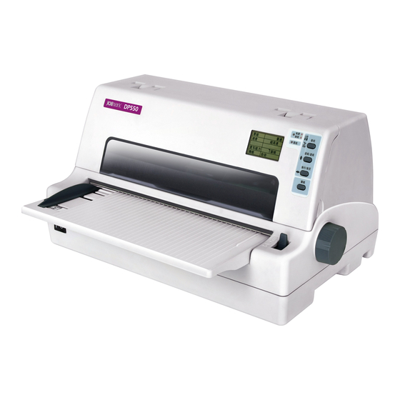
- Page 1 User's Manual DP550 Dot Matrix Printer...
-
Page 2: Important Safety Instructions
DP550 User’s Manual Important Safety Instructions 1. Read all of these instructions carefully and thoroughly and save them for later reference. 2. Follow all warnings and instructions in the manual as well as marked on the product. 3. If the printer has been used just now, please not touch the print head for overheating. -
Page 3: Table Of Contents
DP550 User’s Manual Table of Contents Important Safety Instructions ........................i Chapter 1 Overview ............................1 1.1 Features ..............................1 Chapter 2 Preparation ..........................3 2.1 Unpacking & Checking ........................3 2.2 Removing Protective Materials......................3 2.3 Parts Identification..........................4 2.4 Installing the Printer ..........................4 2.5 Installing and Dismantling the Front Table...................5 2.5.1 Install the Front Table ........................5... - Page 4 DP550 User’s Manual 4.7 Changing the Printing Settings......................28 4.7.1 Using LCD Setup Mode ......................28 4.7.2 Using Setup Menu System ......................28 4.7.3 Online-aptitude Parameter Settings....................31 4.8 Description of Options........................32 4.9 Restoring Default Settings (Without Alignment and the Gap of Print head) ........33 4.10 Using the Self -Test Functions......................33...
-
Page 5: Chapter 1 Overview
Automatic Interface Switching The DP550 includes a USB interface, a parallel interface, an Ethernet interface or a serial interface (According to the specific interface standards). The printer automatically detects the type of data transfer received from the host computer and switches to the respective interface type. - Page 6 DP550 User's Manual Compressing Printing You can set compress print proportion through modifying the Menu System Setting of the printer. (Caution: High Speed mode and Super High Speed mode is invalidated while the printer in Compress printing mode.) In addition, you can set the compress printing through driver. (Only set the compress printing through driver can High Speed printing mode and Super High Speed printing mode are valid.) The compress proportion of...
-
Page 7: Chapter 2 Preparation
DP550 User's Manual Chapter 2 Preparation 2.1 Unpacking & Checking Check the following items in the packing box, if any of these items are missing, please contact your dealer. Figure 2-1 Items in the packing box A: Printer B: Front table... -
Page 8: Parts Identification
DP550 User's Manual 2.3 Parts Identification Figures 2-3 and 2-4 highlight the main parts of the printer. Window LCD display Gap adjust lever Control panel Paper guide Paper feed knob Power switch Front table Print head Paper select lever Ribbon cartridge... -
Page 9: Installing And Dismantling The Front Table
DP550 User's Manual Place space About 10cm About 10cm ≥60 cm Wall About 70cm Floor Figure 2-5 Placement of printer 2.5 Installing and Dismantling the Front Table 2.5.1 Install the Front Table As the follow figure, insert the front table in the slot of the printer's foreside, and then put it horizontal to lock it. -
Page 10: Installing The Paper Feed Knob
DP550 User's Manual 2.6 Installing the Paper Feed Knob The openings of the Paper feed knob aim at the long pin, then insert. (As figure 2-7 shown) Long pin Figure 2-7 Installing the paper feed knob 2.7 Installing the Ribbon Cartridge 1. -
Page 11: Connecting To Your Computer
Install a new one as the above steps. 3. Please use the Jolimark JMR118 ribbon cartridge, otherwise, our company will not guarantee to keep the printer in good repair when it is damaged by unauthorized ribbon cartridge. -
Page 12: Connecting To The Parallel Interface
DP550 User's Manual 2.8.2 Connecting to the Parallel Interface 1. Turn off both the computer and the printer. Plug the parallel interface cable connector securely into the printer's parallel interface. Squeeze the wire clips together until they lock in place on both sides of the connector. -
Page 13: Connecting To The Power Source
CD-ROM → “Driver” → “WIN2000 (XP-Vista-Win7)”, that you can find a file named: DP550.inf, click “Open”, then click “OK”, click “Next”. 6. Follow the direct click “Next” gradually till the installation is finished. - Page 14 5. A window of “Install From Disk” pops up. Please according to the operating system environment, you should select the path as follow: CD-ROM→“Driver”→“WIN2000 (XP-Vista-Win7)”, where you can find a file named: DP550.inf, click “Open”, then click “OK” to return to the window of “Manufacturers/Printers”, click “Next”.
-
Page 15: Network Settings
6. The printer driver process is installed successfully. 2.11 Network Settings Please use Jolimark network setting software NetFinder to set the IP address for Jolimark printers, which can be found in the CD or downloaded from www.jolimark.com. Caution: The network printing function needs the operation system of Windows2000 or above. - Page 16 DP550 User's Manual Button description: Exit — Exit from the software Search — Search printers in the same LAN Assign IP — Modify the IP address and other settings for the specified printer. 2. Search printer Click “Search” button in the main interface, the dialog box appearing will begin searching automatically and show appearance, listing a printer in the main interface if found.
- Page 17 DP550 User's Manual is noted behind the IP address. 1) Correlative description for IP address settings In order to search and set printer’s IP address conveniently for the first time, the factory default setting is DHCP mode which assigns IP address dynamically. If there is no DHCP server in the connected LAN and printer is set to DHCP mode as well, then it will use the internal pre-set address (IP: 10.0.0.1, Subnet Mask: 255.255.255.0) automatically.
-
Page 18: Installing Printer Network Driver
DP550 User's Manual Check the “Use DHCP” if need to assign dynamic address, the settings above will be disabled automatically. Please make sure there is a DHCP server in the network, or the printer can not receive an effective IP address. - Page 19 DP550 User's Manual 5) Come out a window of “Add standard TCP/IP Printer Port Wizard”, click “Next”. 6) Come out a window of “Add Port”, enter the IP address reported by the “Setting printer’s IP address” in the “Printer Name or IP Address” column. Take IP address “192.168.0.240” for example. “Port Name”...
- Page 20 If PC has installed the printer’s driver, set driver’s network port to carry out network printing. The concrete steps are shown below: 1) Click “Start” → “Settings”, select “Printers”. 2) Right click DP550 driver, click “Properties” on the window coming out. 3) Come out a window of “Properties”, click “Ports” and “Add Ports”. - 16 -...
- Page 21 DP550 User's Manual 4) Come out a window of “Printer port”, select “Standard TCP/IP Port”, click “New port”. 5) Come out a window of “Add Standard TCP/IP Printer Port Wizard”, click “Next”. 6) Come out a window of “Add a port”, import the IP address reported by the “Setting printer’s IP address”...
- Page 22 DP550 User's Manual 7) Come out a window of “Additional Port Information Required”, select “Custom” in the “Device Type”, then click “settings”. 8) Come out a window of “Port Settings”. Affirm that “Port name” and “Printer name or IP address”...
- Page 23 DP550 User's Manual 9) Return to “Additional Port Information Required”, click “Next”. 10) Come out a window of “Completing the Add Standard TCP/IP Printer Port Wizard”, click “Finish”. 11) Return to “Printer Ports”, click “Close”. 12) Return to “Properties”, make sure the network port is selected, click “Apply”, and then click “Close”.
- Page 24 DP550 User's Manual - 20 -...
-
Page 25: Chapter 3 Loading Paper
DP550 User's Manual Chapter 3 Loading Paper 3.1 Adjust the Position of the Gap Adjust Lever Adjust the paper-thickness Regardless fixing cut sheet or tractor paper should adjust the gap adjust lever which on the left of the printer first. The gap adjust lever can heighten or lower the carriage to adapt the paper thickness. -
Page 26: Using Tractor Paper
DP550 User's Manual Figure 3-3 Adjust cut sheet Note: 1. Insure the printing contents are all within printable area, or it may cause the print head to break pin. 2. When printing a card, please move the paper guide to “the card position”. -
Page 27: Installing Tractor Paper
DP550 User's Manual 3.3.1 Installing Tractor Paper 1. Connect the printer and the electrical outlet with power cord. 2. Insure the paper select lever in the tractor paper mode as shown in Figure 3-6. Paper select lever Tractor paper Figure 3-6 Adjust the Paper select lever (tractor paper) Note: When changing the type of the paper, please move the paper select lever to the end to insure the paper select lever in the tractor paper mode. -
Page 28: Tearing Off Tractor Paper
DP550 User's Manual Tractor sprocket cover Top of paper Figure 3-9 Install tractor paper on tractor 5. Close the right and left tractor sprocket covers, and then move the right tractor to make sure the tractor paper is smooth enough. Then push down the right tractor sprocket lock lever to lock the tractor as shown in Figure 3-10. -
Page 29: Chapter 4 Control Panel
DP550 User's Manual Chapter 4 Control Panel 4.1 Control Panel Keys, Indicator lights and LCD 4.1.1 Control Panel The control panel consists of four keys and two indicator lights as shown in Figure 4-1. Figure 4-1 Control panel 4.1.2 Indicator light... -
Page 30: Lcd Setup
DP550 User's Manual In offline mode, press LF/FF key to feed the paper line by line. Alternatively, LF/FF hold LF/FF key down, the printer will eject the cut sheet or feed the tractor paper to tear off position. When the tear item is set to “manual”, press TEAR key offline, the tractor TEAR paper will switch between the tear-off position and the printing home position. -
Page 31: Tear-Off Adjustment Mode
DP550 User's Manual When the black mark is set to be open (left black mark or right black mark) in the menu setting, the current adjustment is to adjust the position of the black mark and enter step A. When the black mark is set to be closed in the menu setting, the current adjustment is to adjust the top of form position and enter step B directly. -
Page 32: Changing The Printing Settings
DP550 User's Manual Note: To exit without saving, just turn off the printer. 4.7 Changing the Printing Settings DP550 printers divide printer settings into three sections: LCD setup mode, Setup Menu System and Online-aptitude Parameter Settings. 4.7.1 Using LCD Setup Mode Press ONLINE key for about 3 seconds to enter LCD setup mode. -
Page 33: Current Setting
DP550 User's Manual Current Setting Jolimark DP550 VX.X XXX XXXX/XX/XX SN: XXXXXXXXXXXXXXXXXXX MAC: XX-XX-XX-XX-XX-XX DHCP: YES IP: 10.0.0.1 Subnet: 255. 255. 255.0 gateway: 255.255.255.255 LANGUAGE CHINESE EMULATION CHAR. MODE CHINA FONT SANS SER COURIER PRESTIGE SCRIPT OCR-B OCR-A ORATOR ENG PITCH... - Page 34 The title and main menu are printed out firstly (as Figure 4-3 shown), the default settings are underlined. Print head stays under the current default item. Jolimark DP550 Current Setting Use the LOAD/EJECT key to point the print head to the desired setting.
-
Page 35: Online-Aptitude Parameter Settings
DP550 User's Manual 4.7.3 Online-aptitude Parameter Settings DP550 supports the function of online-aptitude parameter settings, which can be set in the PC with the driver installed in. The detailed setting steps are shown as follows: 1. Make sure that the host and the printer are connected with a cable and both the host and the printer are turned on, the printer should be online as well. -
Page 36: Description Of Options
DP550 User's Manual 4.8 Description of Options Options Description SYSTEM SETUP Choose the set language in menu, menu content will print according to the setting LANGUAGE of the language mode. EMULATION Select the printer emulation of EPSON, ESC/P-K2 or OKI 5530SC CHAR. -
Page 37: Restoring Default Settings (Without Alignment And The Gap Of Print Head)
DP550 User's Manual Skew detect divides into 8 levels from 001-007 and OFF. Skew detect value (right SKEW DETECT and left top of form vertical error value) is from 1.2mm to 4.8mm, each level is 0.6mm discrepancy. SERIAL I/F BAUD RATE Set the printer serial transport speed. -
Page 38: Ascii Printing Test
DP550 User's Manual 4.10.3 ASCII Printing Test One page printing of ASCII slide pattern is performed by turning power on, while pressing the ONLINE key. The printer will exit this printing test and can receive print command to print. Continuous printings of ASCII slide pattern is performed by turning power on, while pressing the ON LINE and LOAD/EJECT keys. - Page 39 DP550 User's Manual Turn on the printer while press LOAD/EJECT + TEAR, enter default parameter adjustment mode. When the ONLINE LED on, long press the LOAD/EJECT key + TEAR key, printer will print out alignment state in current speed. Press LOAD/EJECT key to align up.
-
Page 40: Appendix A
DP550 User's Manual Appendix A A.1 Printer Maintenance Carriage shaft Paper feed platform Figure A-1 Cleaning printer Cleaning periodically and the cleaning tool Periodical cleaning: every six months or every 300 working hours once. Cleaning tool: dry cloth (please use soft cloth to clean metal parts.) Clean the carriage shaft There is a layer of oil covered on the carriage shaft which guarantees the carriage runs smoothly. - Page 41 DP550 User's Manual Phenomenon: The POWER and the ONLINE LEDs blink alternately quickly. Cause: The home position detects error. Solutions: Turn off the power and turn it on again. Paper out or paper jam Phenomenon: The POWER LED blinks and the ONLINE LED turns off.
-
Page 42: Appendix B Specification
DP550 User's Manual Appendix B Specification B.1 General Item Description Type 24-Pin Flatbed Dot Matrix Impact Printer Print direction Bidirectional logic seeking Number of columns 80 columns (10 CPI)/203.2 mm ASCII Chinese Speed 10 CPI 12 CPI Speed 6.7 CPI 7.5 CPI... -
Page 43: Paper Specifications
DP550 User's Manual Length: 55 ~ 536 mm Weight: 45 ~ 250 g/m Width: 76 ~ 260 mm Tractor paper Weight (Single-ply paper): 52 ~ 128 g/m Multi-ply paper (Every page ): 40 ~ 58 g/m Max paper thickness 0.8 mm Original + 6 copies “1 + 2”... -
Page 44: Printable Area
Figure B-2 The printable area of tractor paper B.4 Interface Specification This DP550 printer can be configured with 2.0 Full-Speed USB interface, Centronics (IEEE1284 NIBBLE) parallel interface, RS-232 serial interface or 10/100Base-T Ethernet interface. You can connect the printer to computer according to your requirement. -
Page 45: Usb Interface
DP550 User's Manual B.4.1 USB Interface USB interface is USB 2.0 Full-Speed. USB interface connector is USB-B type connector. (As Figure B-3 shown) Figure B-3 USB-B type connector Name Color VBUS WHITE GREEN BLACK B.4.2 Parallel Interface Standard Centronics (IEEE1284 NIBBLE) parallel interface connector is DB-36 pin type connector. Its pin numbers are as Figure B-4 shown. -
Page 46: Serial Interface
DP550 User's Manual —— /SELECT IN Printer ← Host B.4.3 Serial Interface RS-232 serial interface’s working way is set by the toggle switch on the main board. Interface connector is DB-25 hole type connector. Its connector pin numbers are as the following figure... -
Page 47: Ethernet Interface
DP550 User's Manual DTR: High level denotes the printer is READY to receive data from the HOST; contrarily, Low level denotes the printer is BUSY, and it is forbid receiving data from the HOST. TXD: The printer transmits data. Data bit format: Data bit is fixed 8 bits, Stop bit is fixed 1 bit. -
Page 48: Paper Specification And Printable Area
DP550 User's Manual Figure B-8 Ethernet interface B.5 Paper Specification and Printable Area B.5.1 The Notice Relates to Paper Using the following paper will cause unstable paper feeding, paper jam or paper crease, even leads to break pin. So it can not be used. -
Page 49: Useable Paper Types And Guarantee Area
DP550 User's Manual ◆ Ordinate Paper edge Above 3.8mm Above 3.8mm Paper edge • Please leave the space between centre of the character and the ordinate at least 3.8 mm. B.5.3 Useable Paper Types and Guarantee Area Useable papers are shown in the following table:... - Page 50 DP550 User's Manual Central line Central line Transverse broken line Transverse broken line ◆ The position and size of gear hole The positions and sizes of gear hole are shown below. The central line here refers to the line between the middle of any two holes away the feed direction about 254 mm.
- Page 51 DP550 User's Manual Max 203.2mm ≥4.2mm Printable area ≥13mm ≥13mm ◆ About paper quality Useable qualities of papers are as shown below. Type Paper quality Single-ply paper White high-quality paper Fanfold paper Pressure sensitive paper, inner fanfold paper and mixed paper* * Mixed paper refers to the paper added with carbon paper.
- Page 52 DP550 User's Manual Transverse broken line Less than 1mm Transverse broken line Less than 1mm ◆ Warp between toothed holes of each ply Please use the paper which toothed holes warp between each ply (causes by the warp of fanfold papers superposition) is less than 0.4mm.
-
Page 53: Cut Sheet
DP550 User's Manual ◆ The crease, crimp, puckered and upturning of the paper top and bottom. Please do not use the paper which is crease, puckered, crimp and upturning in the top and bottom. Or it may cause cheap printing quality or paper jam. Especially for the new paper, if it is crease from the first few pages, please do not use it. - Page 54 DP550 User's Manual 3.2mm, but stop at the 80 characters Right printing unguaranteed area when in C value range. Caution: 1. Paper less than 45kg (52kg/m ) is worse in rigidity, so it is not in the guarantee list. 2. Please use the paper with no crease or bend.
- Page 55 DP550 User's Manual Type Paper quality Single-ply paper White high-quality paper Fanfold paper Pressure sensitive paper, inner fanfold paper ◆ The weight of each page of paper and the maximal autotype pages The weight of each page of paper and the maximal autotype pages are shown below.
-
Page 56: Post Card
DP550 User's Manual Papers are easy become puckering, bend or crimp after disposal, transit, pile by people and different conditions of storing. These will affect paper feeding. So please use them after correcting according to following stipulates. Please not use the paper which is not up to the specifications, or it may affect paper feed badly. - Page 57 DP550 User's Manual ○ Normal postcard inserts vertically Postcard inserts direction First character (10CPI) Weight of each level ground paper: 190g (Equal to each page is 190g) Thickness: 0.23 mm Printable area Less than 2 mm : Printable area Unit: mm ○...
-
Page 58: Envelope
DP550 User's Manual B.5.7 Envelope Envelope inserts direction Foldout Printable area Foldout basic end According to different envelope sizes, it is not always first character (10CPI). Sizing place Sizing place Sizing place Sizing place Printable area Foldout Foldout basic end... -
Page 59: Label
DP550 User's Manual B.5.8 Label Caution: Please not use label because it is not included in guarantee list. Problems come out when using label, our company will not guarantee the device and capability. When you have to use label to print, please having enough tests to ensure there is no problem before using it. - Page 60 DP550 User's Manual Label Remove attachment Label Paperboard Produce thickness difference ◆ Please make the label become round corner (R4 〜 R5 mm). ◆ Clipping • Clipping just bring into effect on label (surface base paper) • Clip the label corresponding to the paperboard transverse line, remain a 1-2 mm part in both ends not to clip.
-
Page 61: Delivery Order Form
DP550 User's Manual Size is base on tractor paper size. A: More than 12.7 mm (1/2 inch) B: More than 2.54 mm C: More than 2 mm D: More than 12.7 mm (1/2 inch) E: More than 6.35 mm (1/4 inch) F: More than 6.35 mm (1/4 inch) (more than 12.7 mm as standard)
Need help?
Do you have a question about the DP550 and is the answer not in the manual?
Questions and answers