Table of Contents
Advertisement
Advertisement
Table of Contents

Related Manuals for Jolimark TP850 Series


Summary of Contents for Jolimark TP850 Series
- Page 1 User's Manual TP850 Series Printer...
- Page 2 Corporation names and product names are the registered trademarks or commodity names of the corporation. * Jolimark is a registered trademark of Kong Yue Electronics & Information Industry (XIN HUI) LTD. * EPSON and ESC/POS registered trademarks of Seiko Epson Corporation.
- Page 3 TP850 User’s Manual Warnings, Cautions, and Notes Pay attention to the following promises when using this manual: Warning: Warnings must be followed carefully to avoid bodily injury. Caution: Cautions must be observed to avoid damage to your equipment. Note: Notes contain important information and useful tips on the operation of your printer. - ii -...
-
Page 4: Important Safety Instructions
TP850 User’s Manual Important Safety Instructions Read all of these instructions carefully and thoroughly and save them for later reference. The unauthorized operation would lead to malfunction or accident. Manufacturers have no responsibilities for the problems which are led by unauthorized operations. Follow all warnings and instructions in the manual as well as marked on the product. -
Page 5: Table Of Contents
TP850 User’s Manual Table of Contents Declare................................i Important Safety Instructions ........................iii Chapter 1 Overview ............................1 1.1 Features ..............................1 1.2 Product Model Description ........................1 1.3 Main Parts of the Printer........................1 Chapter 2 Installing the Printer........................3 2.1 Unpacking and Checking ........................3 2.2 Removing the Protective Materials......................3 2.3 Connecting to Your Computer or Other Equipment ................3 2.3.1 Connecting the Cash Drawer Cable .....................3 2.3.2 Connecting the Parallel Cable ......................4... - Page 6 TP850 User’s Manual 5.2.2 Parallel Interface......................... 39 5.2.3 USB Interface ..........................40 5.2.4 Serial Interface ........................... 40 5.2.5 Ethernet Interface ........................42 5.2.6 Power Supply Inlet........................42 Chapter 6 Printer Maintenance ........................ 43 6.1 Cleaning the Printer .......................... 43 6.2 Error Message on the Control Panel ....................43 6.3 Contact the Technical Service Center ....................
-
Page 7: Chapter 1 Overview
According to different data ports (interfaces), TP850 series can be classified into different models: TP850, TP850U, TP850US, TP850UE, TP850UB and TP850UW. TP850 series printers are equipped with auto cutter, so that customer could select full cut or partial cut. Interface:... - Page 8 TP850 User’s Manual Power switch Power supply inlet Data interface Cash drawer interface Figure 1-2 Printer interface Note: Please take the specific interface as standard. - 2 -...
-
Page 9: Chapter 2 Installing The Printer
TP850 User’s Manual Chapter 2 Installing the Printer 2.1 Unpacking and Checking Check the following items in the package, if any of these items is missing, please contact your dealer. AC adapter Printer Power cord Interface cable Driver CD (Including User's Manual and Driver) Roll paper guide (Optional) Figure 2-1 Packing list Note: 1. -
Page 10: Connecting The Parallel Cable
TP850 User’s Manual Cash drawer interface Cash drawer cable Figure 2-2 Connecting the cash drawer cable Caution: Please use the appropriate cash drawer. Manufacturer will not honor warranty when using unauthorized cash drawer. 2.3.2 Connecting the Parallel Cable 1. Make sure the computer and the printer are both turned off, plug the parallel cable to the parallel interface of the printer, Squeeze the wire clips on both sides and make the connector fixed. -
Page 11: Connecting The Serial Cable
TP850 User’s Manual USB interface USB cable Figure 2-4 Connecting the USB cable 2.3.4 Connecting the Serial Cable 1. Make sure the computer and the printer are both turned off, plug the serial cable to the serial interface of the printer. Tighten the screws on both sides and make the cable fixed. As shown in figure 2-5. -
Page 12: Connecting The Power
TP850 User’s Manual Ethernet interface Ethernet cable Figure 2-6 Connecting the Ethernet cable Note: Please refer to the user’s manual for detailed instructions of network settings. 2.4 Connecting the Power 1. Make sure the printer is turned off. (The pressed down side on the switch with “O” mark denotes the printer is off) 2. -
Page 13: Installing The Printer Driver And Selecting The Cutter
TP850 User’s Manual 2.5 Installing the Printer Driver and Selecting the Cutter You should install the printer driver in Windows before using the TP850 printer. Please use the cable to connect computer with printer, then turn on both of them, put the driver CD into the CD-ROM. - Page 14 TP850 User’s Manual 4. A window of “Add Printer Wizard” pops up, click “Have Disk”. 5. A window of “Install From Disk” pops up. Please according to the operating system environment, you should select the path as follow: CD-ROM → “Drivers” → “WIN2000 (XP-Vista-Win7)”, click “Open”, then click “OK”...
-
Page 15: Installing The Bluetooth Interface Driver
TP850 User’s Manual 2.6 Installing the Bluetooth Interface Driver Note: Select to install this driver according to the chosen model. 1. Choose the appropriate Bluetooth adapter, the operation system is Window XP or above which is with Bluetooth adapter driver. 2. - Page 16 TP850 User’s Manual 4. Select the “TP850”, and then click “Next”. TP850 5. Tick off the option of “Let me choose my own passkey” and enter “1234” as shown, then click “Next”. - 10 -...
-
Page 17: Ethernet Settings
Note: Every Bluetooth device has its own address. Please reinstall it when replacing the Bluetooth device. 2.7 Ethernet Settings Please use Jolimark network setting software NetFinder to set the IP address for Jolimark Ethernet interface network printers. NetFinder Software (NetFinder.exe) can be found in the CD or downloaded - 11 -... -
Page 18: Connecting The Printer
TP850 User’s Manual from www.jolimark.com Note: The network printing function needs the operation systems of Windows2000 and above and the operation systems of Window 98/ME and below are not supported. 2.7.1 Connecting the Printer Power on the printer, connect with the Ethernet interface cable which has been connected to LAN, and look into the information of Ethernet LED to ensure the printer has entered the normal connection. - Page 19 TP850 User’s Manual If the printer connects correctly, the IP address can be found in a search period. If the printer still can not be found out when the network connection is correct in the same network. Please check whether the network fire wall on the PC is open or not. If there is fire wall, please close it temporarily, open again after finish searching and setting the printer completely.
-
Page 20: Wi-Fi Setting
“Upgrade-install printer network driver (setting driver’s network port)”. 2.8 Wi-Fi Setting Please use Jolimark network setting software WiFiConfig to set the IP address for Jolimark Wi-Fi interface network printers. Software WiFiConfig (WiFiConfig. exe) can be found in the CD or downloaded from www.jolimark.com. -
Page 21: Connecting The Printer, Using Wificonfig Software
TP850 User’s Manual 2.8.1 Connecting the Printer, Using WiFiConfig Software Connect the printer and computer with the USB cable and turn on the power both of them. Make sure the printer is in the operating state; double click WiFiConfig.exe in the WiFiConfig software of the CD list. - Page 22 TP850 User’s Manual Figure 2 3. Click “Load”, the computer will load the information of the printer and display it on the WiFiConfig software. Click “OK” in the dialogue box “Loading is complete” that pops up. (As figure 3 shown) Figure 3 - 16 -...
- Page 23 TP850 User’s Manual 4. The loaded information is just the setting information of the currently connected printer. For normal use, you need to reset the parameters according to the wireless networks you are using. The detailed settings and description are as follows: Note: Please make sure the wireless network card has been connected to the related router or hotspot before the following operation.
- Page 24 TP850 User’s Manual Double click Local Area Connection 2 SSID Figure 5 - 18 -...
- Page 25 TP850 User’s Manual Security Select the security of the wireless network data. Acquire the security as the following way (Take the operation system WIN XP with selecting “Infrastructure” in the “WLAN type” as an example): (1) Click “Properties” in the window of “Local Area Connection 2 Status”. (Get reference in figure 5) Figure 6 (2) When the window of “Local Area Connection 2 Properties”...
- Page 26 TP850 User’s Manual Figure 7 (3) Select the current wireless network name in the item of “Preferred networks” and then click “Properties”. (As shown in figure 8) - 20 -...
- Page 27 TP850 User’s Manual Figure 8 (4) When the window of “Properties” pops up, find the security in the item of “Wireless network key”. (As shown in figure 9) - 21 -...
- Page 28 TP850 User’s Manual Security Figure 9 Fill in the corresponding key of the wireless network. When “Security” is selected to “None”, you do not need to fill in the key. Printer IP Set the IP address of the printer Wi-Fi interface in the same segment with the wireless networks.
- Page 29 TP850 User’s Manual Click “Support” Figure 10 (2) Figure 11 displays the IP address information of the current wireless networks. Please find out the corresponding wireless network segment according to this IP address and set the printer IP with different IP address in the same segment. In Figure 11, the IP Address is 192.168.43.120 and the segment is 192.168.43.
-
Page 30: Checking Wi-Fi Parameters
TP850 User’s Manual Figure 11 Subnet Mask Set the subnet mask of the printer Wi-Fi interface. It is suggested that the subnet mask should be the same with the wireless networks. (Check the subnet mask in figure 11) Printer Port Set the port number of the printer Wi-Fi interface. -
Page 31: Installing Printer Network Driver
TP850 User’s Manual LEDs Description Network Infrastructure Ad Hoc WLAN type Connect BLINK Disconnect BLINK BLINK 2.9 Installing Printer Network Driver The ways of installing network driver are classified into Newly-install way and Upgrade-install way according to whether the PC is installed the printer driver or not. If the printer driver hasn’t been installed on the PC, adopt newly-install way whose steps are shown in “Newly-install printer network driver”. - Page 32 TP850 User’s Manual 7) A window of “Additional Port Information Required” pops up, select “Custom” in the “Device Type”, then click “Settings”. 8) A window of “Port Settings” pops up. Affirm that “Port name” and “Printer name or IP address” are correct, “Protocol”...
- Page 33 TP850 User’s Manual 9) Return to “Additional Port Information Required”, click “Next”. 10) A window of “Completing the Add Standard TCP/IP Printer Port Wizard” pops up, click “Finish”. 11) In the window of “Install Printer Software”, click “Have Disk”. 12) A window of “Install From Disk” pops up. Please according to the operating system environment, such as Windows 2000/XP/Vista/Win7 operating system you should select the path as follows: CD-ROM →...
- Page 34 TP850 User’s Manual 4) A window of “Printer ports” pops up, select “Standard TCP/IP Port”, click “New port”. 5) A window of “Add Standard TCP/IP Printer Port Wizard” pops up, click “Next”. 6) A window of “Add port” pops up, import the IP address reported by the “Setting printer’s IP address”...
- Page 35 TP850 User’s Manual 7) A window of “Additional Port Information Required” pops up, select “Custom” in the “Device Type”, then click “Settings”. 8) A window of “Port Settings” pops up. Affirm that “Port name” and “Printer name or IP address” are correct, “Protocol”...
- Page 36 TP850 User’s Manual 9) Return to “Additional Port Information Required”, click “Next”. 10) A window of “Completing the Add Standard TCP/IP Printer Port Wizard” pops up, click “Finish”. 11) Return to “Printer Ports”, click “Close”. 12) Return to “Properties”, make sure the network port is selected, click “Apply”, and then click “Close”.
- Page 37 TP850 User’s Manual - 31 -...
-
Page 38: Chapter 3 Control Panel
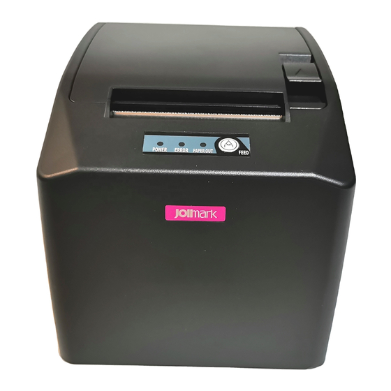
TP850 User’s Manual Chapter 3 Control Panel 3.1 Control Panel There are three LEDs and one button on the control panel. (As Figure 3-1 shown) Figure 3-1 Control Panel 3.1.1 LED Description Denotes whether the printer’s power supply is connected or not. The LED is POWER (Green) on when the power is connected. -
Page 39: Online-Aptitude Parameter Settings
TP850 User’s Manual blinks five times with five beeps, then loosen the button, at this time, the function takes effect and turn off the printer. 3.5 Online-aptitude Parameter Settings TP850 supports the function of parameter settings, which can be set in the PC with the driver installed The concrete setting steps are shown as follows: 1. - Page 40 TP850 User’s Manual 6. To set parameter, first click the parameter icon, then open the parameter setting window. There are Parameter items, Description and Control buttons in the window. Select the corresponding parameter and click “Set”; the printer will change the setting at the time it receives the command. Click “Cancel”...
-
Page 41: Chapter 4 Inserting Paper
TP850 User’s Manual Chapter 4 Inserting Paper The printer can use the paper with the width of 79.5±0.5mm and 57.5±0.5mm conveniently. How to deal with the paper will be explained in details in this chapter. 4.1 Thermal Paper Inserting Steps Caution: 1. - Page 42 TP850 User’s Manual Roll paper Wrong Correct Figure 4-3 The direction of inserting paper Note: Paper edge should be placed down and pulled towards the paper-input slot, but not the opposite. 3. Put the paper edge on the printer as the following figure and close the cover. Roll paper Figure 4-4 Pull out the paper and close the cover Note: After inserting the paper, if PAPER OUT LED and ERROR LED still light, or the printer...
-
Page 43: Chapter 5 Specification
TP850 User’s Manual Chapter 5 Specification 5.1 General Item Description Printing method Thermal line printing Paper feed mode Unidirectional with friction feed Paper eject direction Eject from top Dot density 640 dots/line (203×203 DPI) Printing width Max:80 mm, 640 dots Print speed Max: 300 mm/s Paper feed speed... - Page 44 TP850 User’s Manual Linear bar code: UPC-A, UPC-E, EAN-13, EAN-8, CODE39, CODE12, ITF-25, CODABAR Bar code Two-dimension code: PDF417, QR CODE Voltage: 100 ~ 240 V (AC) Frequency: 50Hz/60Hz Power Supply (AC adapter) Voltage: 24 V (DC) Current: 2.5 A Input voltage: 24 V (DC) Current: 2.5 A Warning: Please use the original AC adapter only.
-
Page 45: Interface
TP850 User’s Manual 5.2 Interface The printer is configured with one cash drawer interface and one data interface (you can select Parallel interface, USB interface, USB interface + Serial interface, USB interface + Ethernet interface, USB interface + Bluetooth or USB interface + Wi-Fi). Connect the computer with the suitable cable. 5.2.1 Cash Drawer Interface The cash drawer interface is RJ-11 interface, shown as below. -
Page 46: Usb Interface
TP850 User’s Manual DATA6 DATA7 DATA8 Acknowledge pulse, Low level means that printer is /ACK ready to receive data. BUSY High level means printer is too busy to receive data. High level means that paper is out. High level with the pull-up resistance. /ERR Low level means the printer is in error status. - Page 47 TP850 User’s Manual Figure 5-5 Pin number of serial interface Table A-3: Pin assignments of serial interface Pin number Signal From Description Host Receive data from Host Printer Sent control code X-ON/X-OFF and data to the Host “MARK” state means printer is too busy to receive data; Printer “SPACE”...
-
Page 48: Ethernet Interface
TP850 User’s Manual Printer 9PIN connector Host 25PIN connector Figure 5-7 The connection figure of host 25 PIN and printer 5.2.5 Ethernet Interface Ethernet interface of 10/100 Base-T can be connected to 10/100M. Figure 5-8 Ethernet interface 5.2.6 Power Supply Inlet The TP850 printer connects with a 24V±10% and 2.5A AC adapter. -
Page 49: Chapter 6 Printer Maintenance
TP850 User’s Manual Chapter 6 Printer Maintenance 6.1 Cleaning the Printer Cleaning periodically and the cleaning tool Periodical cleaning: every 3 months or every 300 working hours once Cleaning tool: dry cloth (please use soft cloth to clean metal parts) Cleaning the spare parts Clean the oily spare parts of the printer with dry cloth. -
Page 50: Chapter 7 Control Commands
TP850 User’s Manual Chapter 7 Control Commands 7.1 General The commands TP850 supplied are based on ESC/POS. The format is described as follows: Command Function Format: ASCII: Indicates the ASCII equivalents Decimal: Indicates the decimal equivalents Hex: Written in hexadecimal code Description: The function and using instruction of that command Example: Some examples will be listed for easier understanding 7.2 Explanation of terms... - Page 51 TP850 User’s Manual n=1: Transmit print status n=2: Transmit off-line status n=3: Transmit error status n=4: Transmit paper sensor status ESC BEL n1 n2 Beep for appointment Format: ASCII: Decimal: Hex: Description: N1 specifies the length of beeping time, n2 specifies the length of intermission time and n3 is the beeping times.
- Page 52 TP850 User’s Manual ESC % Select/cancel user-defined characters set Format: ASCII: Decimal: Hex: Description: n=1, Select the user-defined characters; n=0, Select inter characters. Default: n=0 ESC & Define user-defined characters Format: ASCII: & y c1 c2 [x1 d1..d(y*x1)] [xk d1..d(y*xk)] Decimal: y c1 c2 [x1 d1..d(y*x1)]...
- Page 53 TP850 User’s Manual n=0, 48 Turn underline mode off. n=1, 49 one-dot thick underline mode on two-dot thick underline mode on n=2, 50 ESC 2 Set the line spacing to 3.75mm Format: ASCII: Decimal: Hex: Description: Set the line spacing to 3.75mm. ESC 3 Set the user-defined line spacing Format:...
- Page 54 TP850 User’s Manual ESC E Turn emphasized mode on/off Format: ASCII: Decimal: Hex: Description: When the last bit of the n is 0, the emphasized mode is turned off. When the last bit of the n is 1, the emphasized mode is turned on. ESC J Print and feed paper Format:...
- Page 55 TP850 User’s Manual ESC a n Select justification Format: ASCII: Decimal: Hex: Description: n=0, 48: Left justification; n=1, 49: centering; n=2, 50; right justification. ESC c 3 Select paper sensor Format: ASCII: Decimal: Hex: Description: n=xxxxxxx1B, xxxxxx1xB, xxxxxx11B, Paper near end sensor takes effect. n=xxxxx1xxB, xxxx1xxxB, xxxx11xxB, Paper out sensor takes effect.
- Page 56 TP850 User’s Manual ESC t Select code page Format: ASCII: Decimal: Hex: Description: n=0 PC437 n=1 PC932(katakana) n=2 PC850 n=3 PC860(Portuguese) n=4 PC863(Canadian) n=5 PC865(Nordic) n=6 (West Europe) n=7 (Greek) n=8 (Hebrew) n=9 (East Europe) n=10 Iran n=15 IranII n=16 PC1252 n=17 PC866 n=18 PC852 n=19 PC858...
- Page 57 TP850 User’s Manual FS & Set Chinese mode Format: ASCI: & Decimal: Hex: Description: Enter the Chinese mode. FS - Turn Chinese character underlined mode on /off Format: ASCII: Decimal: Hex: Description: n=0, 48 turn off the Chinese character underline mode. n=1, 49 turn one dot the thick underline of Chinese character mode on.
- Page 58 TP850 User’s Manual FS p n m Print NV bit image Format: ASCII: Decimal: Hex: Description: 1≤n≤64 m=0, 1, 2, 3, 48, 49, 50, 51 Prints the NV bit image n using the mode specified by m. m= 0, 48 Normal mode; m=1, 49 Double width mode; m= 2, 50 Double height mode;...
- Page 59 TP850 User’s Manual GS * Define downloaded bit image Format: ASCII: d1…dk Decimal: d1…dk Hex: d1…dk Description: Define the downloaded bit image in the downloaded graphic area. n1=1~48. n2=1~255. n1×n2<1200, k=n1×n2×8. d specifies the bit image data. n1×8 dots in the horizontal direction and n2×8 dots in the vertical direction. The downloaded bit image is available till printer is powered off or reset.
- Page 60 TP850 User’s Manual GS H Select print position of HRI character Format: ASCII: Decimal: Hex: Description: n=0, 48: NO HRI printing. n=1, 49: above the barcode. n=2, 50: below the barcode. n=3, 51: Both above and below. GS L Set left margin Format: ASCII: Decimal:...
- Page 61 TP850 User’s Manual n=1, 49; Selects character B (8*16) GS h Set bar code height Format: ASCII: Decimal: Hex: Description: Set the height of the bar code to n dots. n=0~255. GS k Print bar code Format: ASCII: d1..dk Decimal: d1..dk Hex: d1..dk...
- Page 62 TP850 User’s Manual GS v 0 Print raster bit image Format: ASCII: d1…dk Decimal: d1…dk Hex: d1…dk Description: Print a raster bit image using the mode specified by m as follows. m=0, 48: normal; m=1, 49: double width; m=2, 50: double height; m=3, 51: quadruple. XL, xH, yL, yH=0~255.
-
Page 63: Appendix Command List
TP850 User’s Manual Appendix Command List Here lists the commands supported in the printer in alphabetical order. Control command Description Beep once Horizontal tab Print and line feed Print and Feed paper to the next black mark position DLE EOT Real-time status transmission ESC BEL Beep for appointment... - Page 64 TP850 User’s Manual FS . Cancel Chinese mode FS 2 User-defined Chinese characters FS S Set Chinese character spacing FS W Turn quadruple-size mode on/off for Chinese character FS p n m Print NV bit image FS q n Define the NV bit image GS BEL Beep for appointment GS !
Need help?
Do you have a question about the TP850 Series and is the answer not in the manual?
Questions and answers