
Related Manuals for Waldorf SN8200E


Summary of Contents for Waldorf SN8200E
- Page 1 I n s t a l l a t i o n a n d O p e r a t i o n M a n u a l Electric Salamander SN8 2 0 0 E SN8 2 0 0 E - B Date Purchased Serial Number Dealer...
- Page 2 MANUFACTURED BY Moffat Limited PO Box 10001 Christchurch New Zealand (03) 389 1007 Fax: (03) 389 1276 WORLD-WIDE BRANCHES UNITED KINGDOM Blue Seal 67 Gravelly Business Park Gravelly Park Birmingham West Midlands B24 8TQ (121) 327 5575 Fax: (121) 327 9711 UNITED STATES Moffat Inc 3765 Champion Blvd...
-
Page 3: Table Of Contents
Contents SN8200E ELECTRIC SALAMANDER (Branding Plate Optional) SN8200E-B ELECTRIC SALAMANDER (With Branding Plate) Introduction ....................2 Specifications .................... 3 Model Numbers Covered in this Specification General Electrical Supply Requirements Dimensions Weight Installation ....................5 Installation Requirements Unpacking Location Clearances Wall Mounting (to non-combustible wall only) -
Page 4: Introduction
Introduction We are confident that you will be delighted with your WALDORF Salamander, and it will become a most valued appliance in your commercial kitchen. To ensure you receive the utmost benefit from your new unit, there are two important things you can do. -
Page 5: Specifications
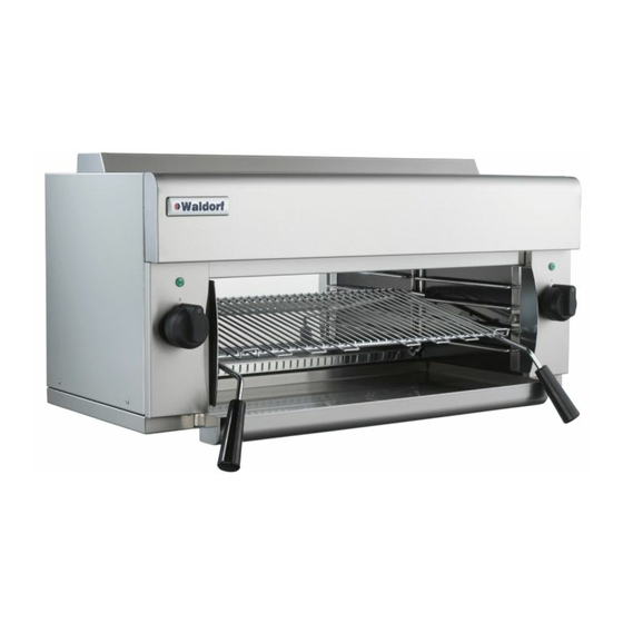
A commercial heavy duty, wall or bench mounted electric fired infra-red grilling Salamander for a wide range of foods. Waldorf Salamanders feature independently controlled heat zones for left and right side of the cooking area. Two efficient high speed infrared elements in the ceiling of the cavity are independently operated with the left and right hand side controls of the appliance. -
Page 6: Dimensions
Specifications Dimensions: E LE C T R IC A L E N TR Y Side Front Plan Internal Dimensions Width 685 mm. Height 230 mm (at front). Depth 330 mm. Cooking Area Rack 610mm x 310mm. Branding Plate (Accessory) 610mm x 310mm. Weight (Nett) 41kg (without Branding Plate or Racking System). -
Page 7: Installation
Installation shall comply with local electrical, health and safety requirements. Waldorf Salamanders are designed to provide years of satisfactory service, and correct installation is essential to achieve the best performance, efficiency and trouble-free operation. This appliance must be installed in accordance with National installation codes and in addition, in accordance with relevant National / Local codes covering electrical and fire safety. -
Page 8: Clearances
Installation Clearances This unit must be installed on a non-combustible wall or tailored stand with the following clearances:- Combustible Surface Non-Combustible Surface Left/Right hand side 50mm Rear 50mm Top Clearance to; Extraction Hood 200mm Grease Arresting Filter 400mm Ceiling (subject to all local regulation requirements) 300mm NOTE: Top clearances can be reduced where local fire protection system is provided, if allowed by the local regulations. -
Page 9: Electrical Connection
Installation Electrical Connection NOTE: ALL ELECTRICAL CONNECTIONS MUST ONLY BE CARRIED OUT BY AN AUTHORISED PERSON. Remove either the left or right hand side panel to allow access to the electrical connection terminal block. Fit the cable through the small grommet located at the rear of the unit and connect to the terminals as marked. -
Page 10: Operation Guide
Only authorised service persons should be used to carry out installation or servicing operations. The Waldorf Salamanders have been designed to provide simplicity of operation and 100% safety protection. Improper operation is therefore almost impossible, however bad operation practices can reduce the life of the salamander and produce a poor quality product. -
Page 11: Operation
Operation Operating the Controls Turning on the Elements to the LOW Position Check that the electrical supply is turned on. ‘1’ Turn the left control knob to the first position marked with a The element will heat up to the LOW setting. Repeat Items 2 to 3 above with the right control knob to heat up the right hand element to the same setting. -
Page 12: Cooking Recommendations
Operation Cooking Recommendations A UTI ON Do not leave the Salamander unattended when in use, as it does cook fast. This equipment has been designed to give a good evenness of heat across the rack area, so toasting, cheese melting and grilling should be relatively even wherever food is placed. ‘3’... -
Page 13: Cleaning And Maintenance
Cleaning and Maintenance A UTI ON Always turn off the power supply before cleaning. This unit is not water proof. Do not use water jet spray to clean interior or exterior of this unit. General To achieve the best results, cleaning must be thorough, and all controls and mechanical parts checked and adjusted periodically by a competent serviceman. -
Page 14: Fault Finding
Fault Finding This section provides an easy reference guide to the more common problems that may occur during the operation of your equipment. The fault finding guide in this section is intended to help you correct, or at least accurately diagnose problems with your equipment. Although this section covers the most common problems reported, you may encounter a problem not cov- ered in this section. -
Page 15: Circuit Diagram
Circuit Diagram Circuit Diagram CONTROL SWITCH SETTINGS 750W 1900W 3000W... -
Page 16: Replacement Parts List
Replacements Parts List Replacement Parts List IMPORTANT: Only genuine authorized replacement parts should be used for the servicing and repair of this appliance. The instructions supplied with the parts should be followed when replacing components. For further information and servicing instructions, contact your nearest authorized service branch (contact details are as shown on the reverse of the front cover of this manual).
Need help?
Do you have a question about the SN8200E and is the answer not in the manual?
Questions and answers