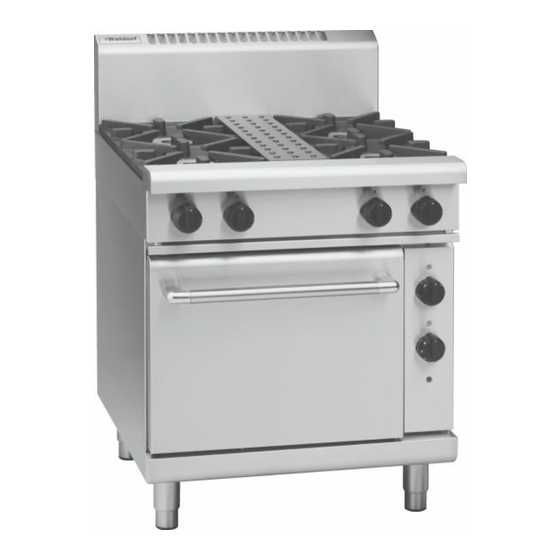
Waldorf RN8510GE Operation Manual
800 series gas ranges electric static/convection oven
Hide thumbs
Also See for RN8510GE:
- Installation and operation manual (37 pages) ,
- Installation and operation manual (33 pages)
Table of Contents
Advertisement
Quick Links
Advertisement
Table of Contents

Related Manuals for Waldorf RN8510GE


Summary of Contents for Waldorf RN8510GE
- Page 1 I n s t a l l a t i o n a n d O p e r a t i o n M a n u a l Gas Ranges Electric Static/Convection Oven RN8510GE/GEC RNL8510GE/GEC RN8610GE/GEC RNL8610GE/GEC RN8810GE/GEC...
- Page 2 MANUFACTURED BY Moffat Limited PO Box 10001 Christchurch New Zealand (03) 389 1007 Fax: (03) 389 1276 WORLD-WIDE BRANCHES UNITED KINGDOM Blue Seal 67 Gravelly Business Park Gravelly Park Birmingham West Midlands B24 8TQ (121) 327 5575 Fax: (121) 327 9711 UNITED STATES Moffat Inc 3765 Champion Blvd...
-
Page 3: Table Of Contents
Contents Waldorf Gas Range Electric Static/Convection Ovens RN(L)8510GE Gas Range Electric Static Oven Four Open Burner. RN(L)8610GE Gas Range Electric Static Oven Six Open Burner. RN(L)8810GE Gas Range Electric Static Oven Eight Open Burner. RN(L)8510GEC Gas Range Electric Convection Oven Four Open Burner. -
Page 4: Introduction
We are confident that you will be delighted with your WALDORF GAS RANGES ELECTRICAL STATIC / CONVECTION OVEN and it will become a most valued appliance in your commercial kitchen. To ensure you receive the utmost benefit from your new Waldorf appliance, there are two important things you can do. -
Page 5: Specification
Specifications Model Numbers Covered in this Specification RN[1]8510GE [2] 4 Open Burners + Electric Static Oven. RN[1]8513GE [2] 2 Open Burners + 300mm Griddle + Electric Static Oven. RN[1]8610GE [2] 6 Open Burners + Electric Static Oven. RN[1]8613GE [2] 4 Open Burners + 300mm Griddle + Electric Static Oven. RN[1]8616GE [2] 2 Open Burners + 600mm Griddle + Electric Static Oven. -
Page 6: Gas Supply Requirements
Specifications Gas Supply Requirements - Non CE Only: Natural Gas LP Gas (Propane) Input Rate (N.H.G.C.) 28 MJ/hr 28 MJ/hr - each Open Burner (26,540 Btu/hr) (26,540 Btu/hr) - each 300 mm Griddle Section 21 MJ/hr 21 MJ/hr (19,900 Btu/hr) (19,900 Btu/hr) 1.13 - 3.40 kPa 2.75 - 4.50 kPa... -
Page 7: Electrical Supply Requirements
1-Phase Connection 3-Phase Connection MODEL 1P+N+E 3P+N+E 230-240V 400-415V L1 - 7.2 Amps 5.5 kW, RN8510GE 5.5 kW L2 - 7.7 Amps 22.6 Amps @ 235 V L3 - 7.7 Amps L1 - 8.5 Amps 5.8 kW, RN8510GEC 5.8 kW L2 - 7.7 Amps... -
Page 8: Dimensions
Dimensions RN(L)8510GE / GEC RN(L)8610GE / GEC Refer to Page 8 for Cook Top Options... - Page 9 Dimensions RN(L)8810GE / GEC Refer to Page 8 for Cook Top Options...
- Page 10 Dimensions Cook Top Options RN(L)8510GE / GEC RN(L)8513GE / GEC RN(L)8613GE / GEC RN(L)8610GE / GEC RN(L)8616GE / GEC RN(L)8619GE / GEC RN(L)8810GE / GEC RN(L)8813GE / GEC RN(L)8819GE / GEC RN(L)8816GE / GEC...
-
Page 11: Installation
Waldorf Gas Range Convection Ovens are designed to provide years of satisfactory service, and correct installation is essential to achieve the best performance, efficiency and trouble-free operation. -
Page 12: Clearances
Installation Clearances NOTE: Only non-combustible materials can be used in close proximity to this appliance. Combustible Surface Non Combustible Surface Left / Right hand side 250mm (*) Rear 50mm * Side clearances can be 50mm when the adjacent surface is at least 100mm below the cooking surface. -
Page 13: Gas Connection
Installation Gas Connection NOTE: ALL GAS FITTING MUST ONLY BE CARRIED OUT BY A QUALIFIED SERVICE PERSON. It is essential that the gas supply is correct for the appliance to be installed and that adequate supply pressure and volume are available. The following checks should therefore be made before installation:- a. -
Page 14: Electrical Connection
Installation Electrical Connection NOTE: ALL ELECTRICAL CONNECTIONS MUST ONLY BE CARRIED OUT BY A QUALIFIED PERSON. WARNING: HIS APPLIANCE MUST BE EARTHED F THE SUPPLY CORD IS DAMAGED IT MUST BE REPLACED BY A SUITABLY QUALIFIED PERSON IN ORDER TO AVOID A HAZARD Each appliance should be connected to an adequately protected power supply and an isolation switch mounted adjacent to, but not behind the appliance. -
Page 15: Commissioning
Installation Commissioning Before leaving the new installation; a. Check the following functions in accordance with the operating instructions specified in the 'Operation' section of this manual. • Light the Griddle. • Light the Open Burners. (F - Flame Failure Option). •... -
Page 16: Operation
/ operator. Waldorf appliances have been designed to provide simplicity of operation and 100% safety protection. Improper operation is therefore almost impossible, however bad operation practices can reduce the life of the appliance and produce a poor quality product. To use this appliance correctly please read the following sections carefully:- •... -
Page 17: Open Burners
Operation Open Burners NOTE: Only cooking pans from size Ø 150mm to Ø 420mm are suitable fo use on these open burners. Flame Failure Option (F-Models) Lighting the Open Burners Flame Failure Protection is incorporated for each burner by way of a thermo-electric system which will shut off the gas supply to that burner in the event that the burner goes out, so that un-burnt gas is not expelled. -
Page 18: Griddle
Operation Griddle AUTIO N The griddle plate temperature reaches over 300°C in hottest points during normal operation at 'Full Flame' setting. These griddles are fitted with a pilot as a standard option and Flame Failure Protection, which is incorporated by way of a thermo-electric system for each main burner. Flame Failure Protection will shut off the gas supply to that burner in the event that the pilot for that burner goes out, so that un-burnt gas is This is an important safety feature which is slowly becoming law throughout the not expelled. - Page 19 Operation Ovens DO NOT USE aluminium foil or trays directly on the cast iron sole plate(s). ! IMPORTANT NEVER block or cover the openings on each side of the sole plate(s). The oven is fitted with top and bottom elements. The thermostat maintains the oven temperature by controlling both elements.
-
Page 20: Cleaning And Maintenance
Cleaning and Maintenance AUTIO N Always turn ‘Off’ the electrical and gas supply before cleaning. This appliance is not water proof. Do not use water jet spray to clean interior or exterior of this appliance. General Clean the range regularly. A clean range looks better, will last longer and will perform better. Carbonised grease on the surface or between the trivets, griddle plates will hinder the transfer of heat from the cooking surface to the food. -
Page 21: Daily Cleaning
Cleaning and Maintenance Daily Cleaning The grease tray(s) should be checked and emptied frequently to prevent overflow and spillage. Remove the grease tray(s) while still warm so that the grease is in a liquid state. Empty any grease from the trays and wash thoroughly in the same manner as any cooking utensil. Clean the control panel with a damp cloth lightly moistened with a solution of mild detergent and water. - Page 22 Cleaning and Maintenance Trivets and Burners Burner Cap a. Remove the trivets from the top of the appliance, taking note that the trivets are manufactured with a lip on one edge, the lip must always be fitted to the outer edge (front and back) of the range.
-
Page 23: Oven Interior
Cleaning and Maintenance Notice Lip on NOTE: It is imperative that the trivet supports are correctly Trivet Edge re-fitted to the unit to ensure that the trivets locate correctly and sit flush and level. NOTE that the trivet support front end side rail profiles are different at either side (Refer to Fig 7) and only one of the side rails seat into the cut-out in the range, whereas the rear end of the trivet support side rail... -
Page 24: Fault Finding
Fault Finding This section provides an easy reference guide to the more common problems that may occur during the operation of your appliance. The fault finding guide in this section is intended to help you correct, or at least accurately diagnose problems with your equipment. Although this section covers the most common problems reported, you may encounter a problem not covered in this section. - Page 25 Fault Finding Fault Possible Cause Remedy Element does not work when Check individual fuses located Replace the blown fuse. turned ‘ON’. behind the control panel. Call the service provider. Check for an electrical short by checking that there is NO continuity between any ‘Phase In’...
-
Page 26: Wiring Schematic
Wiring Schematic RN8510GE RN8610GE RN8810GE... - Page 27 Wiring Schematic Wiring Diagram for RN8510GE RN8610GE RN8810GE...
- Page 28 Wiring Schematic RN8510GEC RN8610GEC RN8810GEC...
- Page 29 Wiring Schematic Wiring Diagram RN8510GEC RN8610GEC RN8810GEC...
-
Page 30: Gas Conversion And Specifications
Gas Conversion and Specifications Conversion Procedure Conversion Procedure NOTE: C AUTI ON AUTIO N • These conversions should only be carried out by qualified persons. All connections must Ensure that the Unit is isolated from the electrical and gas supply before com- Ensure that the appliance is isolated from the electrical and gas supply be checked for leaks before re-commissioning the appliance. - Page 31 Gas Conversion and Specifications Refit all the trivet supports to the top of the appliance. Note ‘Turned Up’ lip on Pot Stand the orientation of the trivet support when re-fitting. The trivet support front end side rail profiles are different from the rear end side rail profiles.
- Page 32 Gas Conversion and Specifications Pilot Injectors a. Unscrew and remove the Pilot Injector Plug from the fitting Pilot Injector at the end of the pilot injector tube using a 11mm A/F Housing spanner. (see Fig 24). b. Using a flat bladed screwdriver, unscrew and remove the pilot injector from the pilot injector housing.
- Page 33 Gas Conversion and Specifications Griddle Pilot Burner a. With the gas supply turned off at the main supply, Gas Control remove the griddle plate section by lifting it straight off Heat Shield the cook top. b. Remove the gas control heat shield from around the griddle burner, this is just a push in fit.
-
Page 34: Gas Regulator
Gas Conversion and Specifications Gas Regulator NOTE: The regulator supplied is convertible between Natural Gas and LPG, but it’s outlet pressure is fixed ex-factory and is NOT to be adjusted. NOTE, Pin rotated for Natural Gas NOTE, Pin rotated for LPG Fig 32 Ensure that the gas and electrical supply are turned off. -
Page 35: Gas Specifications
Gas Conversion and Specifications Gas Specifications - Australia / New Zealand Only Natural. Gas LP Gas (Propane) Main Burner Injectors Ø 2.45mm Ø 1.50mm Open Burner Pilot Burner ('PF' Models only) 0.30 0.20 Main Burner Ø 2.10mm Ø 1.30 m Pilot Burner 0.35 0.23... -
Page 36: Replacement Parts List
Replacement Parts List Replacement Parts List IMPORTANT: Only genuine authorized replacement parts should be used for the servicing and repair of this appliance. The instructions supplied with the parts should be followed when replacing components. For further information and servicing instructions, contact your nearest authorized service branch (contact details are as shown on the reverse of the front cover of this manual). - Page 37 Motor Capacitor 4µf. 228116 Fan. 019479 Motor. General 227015 Pot Stand/Trivet. 228884 Spill Tray (RN8510GE & GEC Series). 228883 Spill Tray (RN8610GE & GEC Series). 228882 Spill Tray (RN8810GE & GEC Series). 227892 Side Rack LH. 227893 Side Rack RH.
Need help?
Do you have a question about the RN8510GE and is the answer not in the manual?
Questions and answers