Waldorf RN8810G Series Installation And Operation Manual
Hide thumbs
Also See for RN8810G Series:
- Installation and operation manual (32 pages) ,
- Installation and operation manual (32 pages) ,
- Installation and operation manual (28 pages)
Table of Contents

Related Manuals for Waldorf RN8810G Series


Summary of Contents for Waldorf RN8810G Series
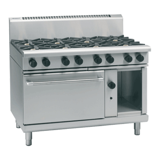
- Page 1 I n s t a l l a t i o n a n d O p e r a t i o n M a n u a l Gas Range Static Oven Se rie s RNL8510G RN 8510G RNL8610G RN8610G RN8810G...
- Page 2 MANUFACTURED BY Moffat Limited Christchurch New Zealand INTERNATIONAL CONTACTS AUSTRALIA Moffat Pty Limited Web: www.moffat.com.au E.Mail: vsales@moffat.com.au Main Office: (tel) +61 (03) 9518 3888 (fax) +61 (03) 9518 3833 Service: (tel): 1800 622 216 Spares: (tel): 1800 337 963 Customer Service: (tel): 1800 335 315 (fax): 1800 350 281 CANADA...
-
Page 3: Table Of Contents
Contents List Waldorf Gas Static Oven Range RN(L)8510G Gas Range Static Oven - 750 mm wide. RN(L)8610G Gas Range Static Oven - 900 mm wide. RN(L)8810G Gas Range Static Oven - 1200 mm wide. Introduction ....................2 Specification ....................3... -
Page 4: Introduction
Introduction We are confident that you will be delighted with your WALDORF GAS RANGE STATIC OVEN and it will become a most valued appliance in your commercial kitchen. To ensure you receive the utmost benefit from your new Waldorf appliance, there are two important things you can do. -
Page 5: Specification
Specifications Model Numbers Covered in this Specification RN[1]8510G [2] Gas Range Static Oven, 4 Open Burners. RN[1]8513G [2] Gas Range Static Oven, 2 Open Burners, 300mm Griddle. RN[1]8610G [2] Gas Range Static Oven, 6 Open Burners. RN[1]8613G [2] Gas Range Static Oven, 4 Open Burners, 300mm Griddle. RN[1]8616G [2] Gas Range Static Oven, 2 Open Burners, 600mm Griddle. -
Page 6: Gas Supply Requirements
Specifications Gas Supply Requirements - Non - CE Only: Natural Gas LP Gas (Propane) Input Rate (N.H.G.C.) 28 MJ/hr 28 MJ/hr - each Open Burner (26,540 Btu/hr) (26,540 Btu/hr) - each 300 mm Griddle Section 21 MJ/hr 21 MJ/hr (19,900 Btu/hr) (19,900 Btu/hr) - Oven 30 MJ/hr... -
Page 7: Dimensions
Dimensions RN(L)8510G Cook Top Options RN(L)8510G RN(L)8513G... - Page 8 Dimensions RN(L)8610G Cook Top Options RN(L)8610G RN(L)8613G RN(L)8619G RN(L)8616G...
- Page 9 Dimensions RN(L)8810G Cook Top Options RN(L)8810G RN(L)8813G RN(L)8816G RN(L)8819G...
-
Page 10: Installation
Waldorf Gas Range Static Ovens are designed to provide years of satisfactory service, and correct installation is essential to achieve the best performance, efficiency and trouble-free operation. -
Page 11: Clearances
Gas Connection NOTE: ALL GAS FITTING MUST ONLY BE CARRIED OUT BY AN QUALIFIED PERSON. Waldorf Gas Range Static Ovens do not require an electrical connection, as they function totally on the gas supply only. It is essential that gas supply is correct for appliance to be installed and that adequate supply pressure and volume are available. -
Page 12: Commissioning
Installation Regulator connections are " BSP female. Connection to appliance is " BSP male. (Refer to ‘Specifications’ section for gas supply location dimensions). NOTE: A Manual Isolation Valve must be fitted to the individual appliance supply line. Correctly locate appliance into its final operating position and using a spirit level, adjust legs so that appliance is level and at correct height. -
Page 13: Operation
/ operator. Waldorf appliances have been designed to provide simplicity of operation and 100% safety protection. Improper operation is almost impossible, however bad operation practices can reduce the life of the appliance and produce a poor quality product. -
Page 14: Open Burners
Operation Open Burners NOTE: Only cooking pans from size Ø 150 mm to Ø 420 mm are suitable fo use on these open burners. Flame Failure Option (F-Models) Lighting the Open Burners Flame Failure Protection is incorporated for each burner by way of a thermo-electric system which will shut off gas supply to that burner in event that burner goes out, so that un-burnt gas is not expelled. -
Page 15: Griddle
Operation Griddle Caution Griddle plate temperature reaches over 300°C in hottest points during normal operation at 'Full Flame' setting. Lighting the Griddle a. Depress gas control knob and rotate anti-clockwise to ‘Pilot’ position. b. With gas control knob depressed, press piezo ignition button to ignite pilot burner. Repeat Items 1 to 2 until pilot is lit. -
Page 16: Lighting The Oven Main Burner
Operation Control Knob in Main Lighting the Oven Main Burner Burner Operating Position Ensure pilot burner is alight. Rotate thermostat control knob anti-clockwise to desired temperature marked on knob. Main burner will now ignite automatically, from pilot burner. Rotate Knob Anti-Clockwise to Operating Temperature Control Knob in Turning the Oven to ‘Stand-by’... -
Page 17: Cleaning And Maintenance
Cleaning and Maintenance General Caution Always turn off the gas supply before cleaning. This appliance is not water proof. Do not use water jet spray to clean interior or exterior of this appliance. Clean the range regularly. A clean range looks better, will last longer and will perform better. Carbonised grease on surface or between trivets, griddle plates will hinder transfer of heat from cooking surface to food. -
Page 18: Daily Cleaning
Cleaning and Maintenance Daily Cleaning Grease / spill trays should be checked and emptied frequently to prevent overflow and spillage. Remove grease drawer while still warm so that grease is in a liquid state. Empty any grease from drawer and wash thoroughly in same manner as any cooking utensil. Remove burner caps and bases, trivets and thoroughly clean splash back, interior and exterior surfaces of range with hot water, a detergent solution and a soft scrubbing brush. - Page 19 Cleaning and Maintenance Trivets and Burners Burner Cap a. Remove trivets from top of appliance, taking note that trivets are manufactured with a lip on one edge, lip must always be fitted to outer edge (front and back) of range. (See Fig 10).
-
Page 20: Periodic Maintenance
Cleaning and Maintenance Notice Lip on Trivet Edge NOTE: It is imperative that trivet supports are correctly re-fitted to appliance to ensure that trivets locate correctly and sit flush and level. NOTE that trivet support front end side rail profiles are different at either side (Refer to Fig 6) and only one of side rails seat into cut-out in range, whereas rear end of trivet support side rail profiles are same and have 2... -
Page 21: Fault Finding
Fault Finding your appliance. The fault finding guide in this section is intended to help you correct, or at least accurately diagnose problems with your equipment. Although this section covers most common problems reported, you may encounter a problem not covered in this section. -
Page 22: Gas Conversion And Specifications
Gas Conversion and Specifications Conversion Procedure Caution Ensure that the Appliance is isolated from the gas supply before commencing servicing. NOTE: These conversions should only be carried out by qualified persons. All connections must be checked for leaks before re-commissioning the appliance. Adjustment of components that have adjustments / settings sealed (e.g. - Page 23 Gas Conversion and Specifications Piezo Igniter Griddle Pilot Supply Tube Carry out the following:- Remove griddle plate section and heat shield. Remove main burner. Disconnect piezo igniter from mounting bracket. (For access purposes). Pilot Burner Disconnect pilot supply tube from pilot burner to access pilot injector.
- Page 24 Gas Conversion and Specifications Static Oven Pilot Burner Carry out the following:- Piezo Igniter Remove lower lintel at front of oven. Thermocouple Open oven door and remove sole plate(s). Remove main burner. Main Burner Remove thermocouple and piezo igniter from mounting bracket.
-
Page 25: Gas Specifications
Gas Conversion and Specifications Commissioning Before leaving the installation; Check all gas connections for leakage using soapy water or other gas detecting equipment. Warning O NOT USE A NAKED FLAME TO CHECK FOR GAS LEAKAGES Carry out a ‘Commissioning’ check of appliance as shown in Installation Section of this manual. Ensure any adjustments done to components that have adjustments / settings paint sealed are to be re-sealed. -
Page 26: Replacement Parts List
Replacement Parts List Replacement Parts List IMPORTANT: Only genuine authorized replacement parts should be used for servicing and repair of this appliance. Instructions supplied with parts should be followed when replacing components. further information servicing instructions, contact your nearest authorized service branch (contact details are as shown on reverse of front cover of this manual). - Page 27 Pot Stand / Trivet. 228884 Spill Tray (750mm - RN8510G Series). 228883 Spill Tray (450mm - RN8610G Series). 228882 Spill Tray (600mm - RN8810G Series). 229674 Rear Roller Assy. 227850 Adjustable Leg (150mm). Gas Conversion Kits Gas Type to Convert to Models...
Need help?
Do you have a question about the RN8810G Series and is the answer not in the manual?
Questions and answers