Waldorf 800 Series Installation And Operation Manual
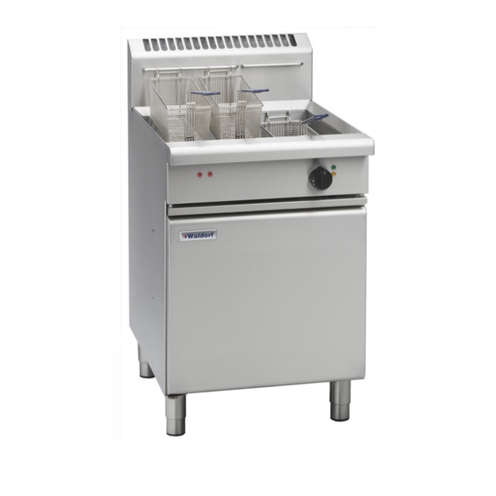
Fast-fri gas fryer
Hide thumbs
Also See for 800 Series:
- Installation and operation manual (32 pages) ,
- Operation manual (39 pages) ,
- Installation and operating manual (19 pages)

Subscribe to Our Youtube Channel
Related Manuals for Waldorf 800 Series


Summary of Contents for Waldorf 800 Series
- Page 1 I n s t a l l a t i o n a n d O p e r a t i o n M a n u a l HPO Fast-Fri Gas Fryer FN 8 1 30 G H PO FN B8 1 30 GH PO FN L 8 13 0 GH PO FN L B8 13 0 GH PO...
- Page 2 Moffat Limited Rolleston 7675 New Zealand AUSTRALIA Moffat Pty Limited E.Mail: vsales@moffat.com.au Main Office: (tel): +61 (03) 9518 3888 (fax): +61 (03 9518 3833 Service: (tel): 1800 622 216 Spares: (tel): 1800 337 963 Customer Service: (tel): 1800 335 315 (fax): 1800 350 281 CANADA Serve Canada...
- Page 3 Waldorf GHPO Gas Fryer FN(L)(B)8130GHPO 'FAST-FRI' GAS FRYER (Single Tank - 31 ltr) Model Numbers Covered in this Specification Gas Supply Requirements Electrical Supply Requirements Installation Requirements Unpacking Location Clearances Assembly Electrical Connection Fitting Rear Rollers Gas Connection Commissioning Operation Guide...
- Page 4 We are confident that you will be delighted with your Waldorf HPO Fast-Fri Gas Fryer and it will become a most valued appliance in your commercial kitchen. To ensure you receive the utmost benefit from your new appliance, there are two important things you can Please read the instruction book carefully and follow the directions given.
- Page 5 FN[1]8130GHPO 'FAST FRI' GAS FRYER (Single Tank - 31 ltr). NOTE: [1]: - Model Options; - Standard. - Low Back. - Bold Front. - Low Back and Bold Front. - Australia: Input Rating (N.H.G.C.) 140 MJ/hr 140 MJ/hr Supply Pressure 1.13 - 3.40 kPa 2.75 - 3.40 kPa Burner Operating Pressure (*)
- Page 7 Waldorf 'FAST-FRI' HPO Fryers are designed to provide years of satisfactory service, and correct installation is essential to achieve the best performance, efficiency and trouble-free operation.
- Page 8 NOTE: Only non-combustible materials can be used in close proximity to this appliance. To allow easy operation, drainage and servicing of appliance, a minimum of 600mm clearance should be maintained at front of appliance. Any gas burning appliance requires adequate clearance and ventilation for optimum and trouble-free operation.
- Page 9 Appliance Raise appliance from the floor by approx. Base 75mm using suitable lifting equipment (i.e. Palletiser / Forklift) to allow rear adjustable feet to be removed. Unscrew and remove both rear adjustable feet from rear leg housings. Fit rear roller to rear leg housing and align screw hole in side of rear leg housing with threaded hole in rear roller.
- Page 10 NOTE: ALL GAS FITTING MUST ONLY BE CARRIED OUT BY AN AUTHORISED PERSON. This appliance can be configured to have underside or rear entry gas supply. To convert this appliance, see the Gas Supply Connection Location Conversion section of this manual for instructions.
- Page 11 Check gas supply pressure is as shown in Specifications section, Gas Supply Requirements table. Supply Pressure Test Point NOTE: Measure supply pressure at Upper Test Point (Supply Pressure) on gas control valve. Pressure Adjusting Screw Light Main Burners. Refer to ‘Operation’ section, ‘Lighting the Main Burners’.
- Page 12 REAT CARE MUST BE TAKEN BY OPERATOR TO USE THE RYER SAFELY TO GUARD AGAINST RISK OF INJURY AND FIRE DO NOT LEAVE FRYER UN ATTENDED DURING OPERATION DO NOT HOT. REPLENISH THE OIL FRYING MEDIUM IN THE FRYER WHEN THE FRYER IS ...
- Page 13 WHEN COLD. Fig 5 NOTE: WALDORF 'FAST-FRI HPO' fryers can be used with both oil and shortening. Before filling the tank, always check that the drain valve, located behind the access door, is closed. A locking slide is provided on the valve and this should always be locked in position during use.
- Page 14 Main burners will operate automatically to maintain this temperature. As a safety precaution all Waldorf 'Vee-Ray' fryers feature an Over-Heat control which will turn Off the fryer in the event that the oil reaches over 220°C, should there be a thermostat failure.
- Page 15 DO NOT USE FLAMMIBLE SOLVENTS AND CLEANING AIDS ON OR IN CLOSE PROXIMITY TO RYER WHILST HOT. RYER IS STILL To achieve the best results, cleaning must be regular and thorough and all controls and mechanical parts checked and adjusted periodically by a competent serviceman. If any small faults occur, have them attended to promptly.
- Page 16 Opening the Drain Valve OT OIL WILL BURN OT RUSH THIS JOB a. Lift locking slide on valve handle (Fig 7) to release the valve. b. While holding locking slide in withdrawn position, rotate handle anticlockwise (Fig 8) to open valve. Locking c.
- Page 17 NOTE: If fryer usage is very high, we recommend the weekly cleaning procedure is carried out more frequently. Proceed to drain and filter the tank as for Daily Cleaning . Do not refill tank with frying medium until it has been cleaned as shown below. Fill fryer with cold water to normal fill level and add a high quality commercial cleaner that has been All purpose cleaners are not recommended specifically formulated for fryers.
- Page 18 This section provides an easy reference guide to the more common problems that may occur during the operation of your equipment. The fault finding guide in this section is intended to help you correct, or at least accurately diagnose problems with your equipment. Although this section covers the most common problems reported, you may encounter a problem not covered in this section.
- Page 19 Insufficient turnover of oil. Maintain a minimum quantity of oil in fryer for more rapid turnover or increase the quantity of food fried in fryer. Replace with fresh oil every 3 to 5 days. Continual frying with excess moisture on Drain foods before frying, pat food dry.
- Page 20 This guide shows the most likely cause of failure should a fault occur. The information provided should enable quick identification of the most probable faults. Should you have problems that are not covered here, please contact your local authorised service agent who will help you identify and resolve the problem. Please note that the service agent will require the following information:- ...
- Page 22 NOTE: This conversion should only be carried out by qualified persons. All connections must be checked for leaks before re-commissioning appliance. To convert the unit from Underside to Rear entry gas supply, perform the following steps: Remove rear panel, Unscrew universal joint, Remove supply pipe fastening screws from lower mounting bracket, Reposition supply pipe to align with upper mounting bracket,...
- Page 23 NOTE: These conversions should only be carried out by qualified persons. All connections must be checked for leaks before re-commissioning the appliance. For all relevant gas specifications refer to the table at the rear of this section. Injector Gas Mixer Supply Tube Unscrew the injector gas supply tube fitted into the blower /...
- Page 24 On completion of the gas conversion, replace the gas type identification label located at:- - Rear of appliance, above the gas connection point. - Beside rating plate. Before leaving the converted installation; Check all gas connections for leakage using soapy water or other gas detecting equipment. Check the following functions in accordance with operating instructions specified in 'Operation' section of this manual.
- Page 25 - Australia: Main Burner Injectors 4.30mm 2.40mm Aeration Plate 20 x Ø 9.55 holes 16 x Ø 9.55 holes Operating Pressure 0.87 kPa (*) 2.55 kPa (*) Supply Pressure 1.13 - 3.40 kPa 2.75 - 3.40 kPa - New Zealand: Main Burner Injectors 4.30mm 2.40mm...
-
Page 26: Replacement Parts List
Controls 022594 Gas Control Valve SIT 840. 023163K Burner Kit. 235357 Thermostat Knob Waldorf 6mm 195 - 100°C. 229685 Temperature Control PC Board. 020117 Thermostat Probe. 242757K Overtemp Thermostat Kit 2019. 022593 Electronic Ignition/valve control module .
Need help?
Do you have a question about the 800 Series and is the answer not in the manual?
Questions and answers