Table of Contents
Advertisement
I
n
s
t
a
l
I
n
s
t
a
l
FLIR Systems, Inc.
70 Castilian Drive
Goleta, CA 93117
Phone: 888.747.FLIR (888.747.3547)
International: +1.805.964.9797
427-0016-00-10 Revision 120
P
T
Z
P
T
Z
P
T
Z
P
T
Z
l
a
t
i
o
n
a
n
d
l
a
t
i
o
n
a
n
-
3
5
M
-
3
5
M
-
5
0
M
-
5
0
M
O
p
e
r
a
t
i
d
O
p
e
r
a
t
i
Copyright © 2008 FLIR Systems, Inc.
S
S
S
S
o
n
M
a
n
u
a
o
n
M
a
n
u
May 2008
http:// www.flir.com
l
a
l
1
Advertisement
Table of Contents

Related Manuals for FLIR PTZ-35 MS


Summary of Contents for FLIR PTZ-35 MS
- Page 1 May 2008 FLIR Systems, Inc. 70 Castilian Drive Goleta, CA 93117 Phone: 888.747.FLIR (888.747.3547) International: +1.805.964.9797 http:// www.flir.com 427-0016-00-10 Revision 120 Copyright © 2008 FLIR Systems, Inc.
- Page 2 COPYRIGHT Copyright © 2008 by FLIR Systems, Inc. All rights reserved. This publication, or any parts thereof, may not be reproduced in any form without the express written permission of FLIR Systems, Inc.
-
Page 3: Table Of Contents
Pan/Tilt Panel ......................13 Infrared Panel ......................14 DLTV Panel ......................... 16 Manual Control Panel ....................17 5.0 PTZ-35 MS / PTZ-50 MS PHYSICAL INTERFACE ........19 Dimension Drawings ....................19 Integrated Interface Cable Connector ................. 21 Break-Out Connector Cable ..................22 6.0 MAINTENANCE .................. -
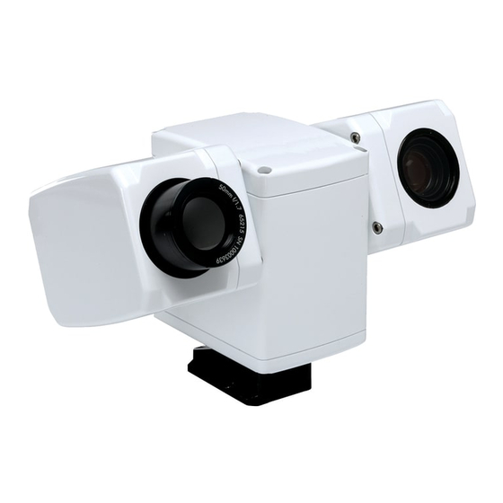
Page 4: Figure 1: Ptz-35 Ms And Ptz-50 Ms Provide 24/7 Threat Detection
Figure 2: Daylight camera on left; Thermal image on right ..............6 Figure 3: Backlit daylight camera on left; thermal image on right ............7 Figure 4: PTZ-35 MS / PTZ-50 MS camera foot and mounting bracket shoe........8 Figure 5: Quick Connect Interface Cable w/ break-out pigtail shown at bottom insert......9 Figure 6: PTZ-35 MS / PTZ-50 MS User Interface ................10... -
Page 5: Warnings And Cautions
Protect Your Investment The enclosure of the PTZ-35 MS and PTZ-50 MS visible camera is pressurized with nitrogen to eliminate fogging of the camera lens due to sudden changes in temperature. -
Page 6: Introduction
FLIR’s powerful thermal security cameras compliment and complete your security camera network. They turn night into day, allowing you to see intruders invisible to the naked eye. FLIR PTZ cameras create video images from infrared thermal energy (heat), and perform well at night and day, in good weather and bad. -
Page 7: Advantages Of Thermal Imaging
PTZ-35 MS The PTZ-35 MS camera features a focal length of 35mm, providing a short to medium field of view of 20° and is well-suited for short range threat detection in all circumstances. It gives you a wide field of view, so you can cover a large area and keep excellent situational awareness. Like all FLIR thermal cameras, the PTZ-35 MS provides crisp, clear thermal imagery in total darkness, haze, light fog or smoke. -
Page 8: Package Contents
FLIR Systems Customer Support immediately using the contact information at the front of this manual. Figure 4: PTZ-35 MS / PTZ-50 MS camera foot and mounting bracket shoe 427-0016-00-10 Revision 120 Copyright © 2008 FLIR Systems, Inc. -
Page 9: Quick-Start Information
9. Plug the AC/DC converter into an electrical outlet. Insert the circular plug of the power converter to the connection labeled “POWER” on the break-out pigtail. 10. Now the PTZ-35 MS / PTZ-50 MS camera is ready for use. Note that the device will immediately zero itself and return back to home position upon applying power. -
Page 10: Ptz-35 Ms / Ptz-50 Ms User Interface
You have now completed the basic steps for setup of the PTZ-35 MS / PTZ-50 MS. However, it is recommended that you read the rest of this User’s Manual to learn how to adjust the PTZ-35 MS / PTZ-50 MS system settings according to your preferences. -
Page 11: Communication Panel
The Communication Panel tab, shown in Figure 6, is located on the left-side of the About tab. The PTZ-35 MS / PTZ-50 MS can communicate at the 2400, 4800, 9600 & 57600 baud rates and both pan/tilt as well as camera control can be accessed. To access the device, simply choose the camera control switch and select the correct COM port that is connected to your PC. -
Page 12: Flir Systems, Inc
It is recommended to use the fastest baud rate possible. • The GUI will have an easier time connecting to the PTZ-35 MS / PTZ-50 MS if the hardware is powered up prior to opening the software. •... -
Page 13: Pan/Tilt Panel
Pan/Tilt Panel The Pan/Tilt panel, shown in Figure 9, provides the ability to control the azimuth and elevation mechanism along with preset locations for the PTZ-35 MS / PTZ-50 MS. Pan/Tilt Drive: provides pan/tilt direction and positioning 1. Presets. The preset buttons allow the user to set/get 3 preset locations and determine the home location. -
Page 14: Infrared Panel
PC. The Video and AGC tab provides for basic image optimization along with camera control. The General tab allows for further camera control to set power-on defaults and get further camera data. The infrared camera commands for the PTZ-35 MS / PTZ-50 MS software interface are listed in section 9.0 Software Control Functions. -
Page 15: Figure 10: Ptz-35 Ms / Ptz-50 Ms Infrared Panel
Figure 10: PTZ-35 MS / PTZ-50 MS Infrared panel General: provides the user to save the default settings and monitor sensor or FPA temp 1. FPA Temperature. This command gets the FPA or sensor temperature and displays in degrees C. The FPA Temperature can also be monitored by depressing the “Monitor FPA Temp?”... -
Page 16: Dltv Panel
Figure 11: PTZ-35 MS / PTZ-50 MS Infrared panel DLTV Panel The DLTV panel contains the daylight camera settings as shown in the Figure 12. These commands provide the ability to control the daylight camera from the PC. Zoom: provides the user to control the daylight camera zoom and focus. -
Page 17: Manual Control Panel
2. Reset. This will reset the entry to all zeros. A list of commands is in Section 9.0 Software Control Functions. For a complete list of the commands refer to the PTZ-35 MS / PTZ-50 MS Software Interface Control Document or ICD 102- 1270-151. -
Page 18: Figure 13: Ptz-35 Ms / Ptz-50 Ms Manual Control
Figure 13: PTZ-35 MS / PTZ-50 MS Manual Control 427-0016-00-10 Revision 120 Copyright © 2008 FLIR Systems, Inc. -
Page 19: Ptz-35 Ms / Ptz-50 Ms Physical Interface
PTZ-35 MS / PTZ-50 MS PHYSICAL INTERFACE Dimension Drawings The following figures show a dimensional drawing of the PTZ-35 MS / PTZ-50 MS. Remember to firmly secure the unit and allow for device travel (pan and tilt). Figure 14: PTZ-35 MS / PTZ-50 MS Dimension Drawing 427-0016-00-10 Revision 120 Copyright ©... -
Page 20: Figure 15: Ptz-35 Ms / Ptz-50 Ms Dimension Drawing With Hole Pattern
Figure 15: PTZ-35 MS / PTZ-50 MS Dimension Drawing with hole pattern 427-0016-00-10 Revision 120 Copyright © 2008 FLIR Systems, Inc. -
Page 21: Integrated Interface Cable Connector
Contacts Pines Shell Style Cable plug Insert Position Keyring Interface cable connector front view (Male) Chassis connector front view (Female Figure 16: PTZ-35 MS / PTZ-50 MS Interface Cable Connector Function Pin Signal Name Function Signal Name Power VDC1 Comms... -
Page 22: Break-Out Connector Cable
Break-Out Connector Cable The PTZ-35 MS / PTZ-50 MS also include a break-out cable (as shown in Figure 5) that connects to the integrated interface cable with single terminal connectors. The break-out cable has the MIL- C-26482 Series 1 Connector (Female) on one end and five pig-tail leads of the following: Input voltage range: 24 VDC ±10 % with 24 VDC optimum value... -
Page 23: Maintenance
Repeat several times with different pieces of tissue. 2. Repeat the same step using IPA instead of water. Drag the final piece of tissue over the lens several times to prevent pooling, which could leave a residue behind. 427-0016-00-10 Revision 120 Copyright © 2008 FLIR Systems, Inc. -
Page 24: Ptz-35 Ms / Ptz-50 Ms Specifications
PTZ-35 MS / PTZ-50 MS SPECIFICATIONS • Power/Weight : Input Voltage Range: 24 VDC ±10 % Sensor Weight w/o 3628 g (8 lbs) cable: • Pan/Tilt Specifications: Azimuth Elevation Motion Range (º) ± 200 ± 60 Angular Velocity 1 to 80 1 to 40 (º/sec) -
Page 25: Flir Systems, Inc
Solar Thermal Loading MIL-STD-810E, Method 505.3, procedure I, paragraph 1 3.2.b1 o External Icing MIL-STD-810E, Method 521.1, 6 mm ice thickness o Wind Load 35 mph Note: These specifications are subject to change without notice. 427-0016-00-10 Revision 120 Copyright © 2008 FLIR Systems, Inc. -
Page 26: Optional Joystick Display Unit
& the motion will be blurred. Vibration Press & hold YELLOW 2ND button & press (DISPLAY) “HI” – the top GREEN LED will flash slowly & the Vibration should decrease. 427-0016-00-10 Revision 120 Copyright © 2008 FLIR Systems, Inc. -
Page 27: Joystick Drift
Caution: The unit should be operated by a person other than the driver while vehicle is in use. When not in use, remove power jack from Joystick Display Unit. Figure 23: Operational Directions on back of Joystick Display Unit 427-0016-00-10 Revision 120 Copyright © 2008 FLIR Systems, Inc. -
Page 28: Software Control Functions
Flow Control None 9.2 IR Imager This section describes the structure of the commands of the IR imager on the PTZ-35 MS / PTZ-50 MS. Note that all data values are called out in hexadecimal. The command and response strings of the IR imager interface are of variable length, ranging from 10 bytes to 32 bytes. -
Page 29: Flir Systems, Inc
Defaults Get Serial 6E0000650000AF200000 6E0000650004EFA4000(aabbccdd)0E S/N aabbccdd Number Get Version 6E0000050000344B0000 6E0000050008B543(abcdefghijklmnop)0DF7 Software ab.cd.ef.gh FPGA ij.kl.mn.op Set FFC Mode Auto 6E00000B00020F0800000000 6E00000B00020F0800000000 Manual 6E00000B00020F0800011022 6E00000B00020F0800011022 Do FFC 6E00000C0000AADA0000 E-Zoom 6E00000F0002D3C800000000 6E00000F0002D3C800000000 427-0016-00-10 Revision 120 Copyright © 2008 FLIR Systems, Inc. -
Page 30: Flir Systems, Inc
6E00004C0008367FFF60FFC400A0003C8317 6E00004C0008367FFF60FFC400A0003C8317 Horizon 6E00004C0008367FFF60FFE200A0001E4206 6E00004C0008367FFF60FFE200A0001E4206 Optimized 6E00004C0008367FFF60FFC400A0000074C8 6E00004C0008367FFF60FFC400A0000074C8 Optimized Ground 6E00004C0008367FFF60000000A0003C6D16 6E00004C0008367FFF60000000A0003C6D16 Optimized Center 75% 6E00004C0008367FFF88FFD30078002DA5F2 6E00004C0008367FFF88FFD30078002DA5F2 Center 50% 6E00004C0008367FFFB0FFE20050001EE03A 6E00004C0008367FFFB0FFE20050001EE03A Center 25% 6E00004C0008367FFFD8FFF10028000F59BC 6E00004C0008367FFFD8FFF10028000F59BC Set Detail Enhancemen 10 6E0000D30008627700003090106400043967 6E0000D30000E37F0000 427-0016-00-10 Revision 120 Copyright © 2008 FLIR Systems, Inc. -
Page 31: Daylight Camera
6E00005500024AC7007DAF3A 9.3 Daylight Camera This section describes the structure of the commands of the daylight camera on the PTZ-35 MS / PTZ-50 MS Sensor. Note that all data values are called out in hexadecimal. The command and response strings of the daylight camera interface are of variable length, ranging from of 5 to 32 bytes. -
Page 32: Pan/Tilt Mechanism
LSB = 0.5 deg. 9.4 Pan/Tilt Mechanism This section describes the structure of the commands for the Pan/Tilt on the PTZ-35 MS / PTZ-50 MS Sensor. Note that all data values are called out in hexadecimal. The command and response strings of the Pan / Tilt Mechanism interface are of variable length, ranging from 5 to 32 bytes. -
Page 33: Flir Systems, Inc
90 41 FF 90 51 FF VV=Pan Speed, 0 to FE = fastest WW=Tilt Speed, 0 to FE = fastest Min value = 28 typical Stop 81010601VVWW0303 FF 90 41 FF 90 51 FF 427-0016-00-10 Revision 120 Copyright © 2008 FLIR Systems, Inc. -
Page 34: Flir Systems, Inc
Position) example 135.5 = 00 08 07 08, LSB=1/2° GG=Pan Speed, 00H to 18H, 18H= 86 deg/s, 00H=5 deg/s Set (Current 90 41 FF 90 51 FF HH= Tilt Speed Position) 427-0016-00-10 Revision 120 Copyright © 2008 FLIR Systems, Inc. -
Page 35: User Controls For Kbd300A
140, 160, 200, 60, 100, 120 Photon 7, Aux Off Toggle: Max gain value 8, 10, 12, 2, 4, 6 Note: If communication unsuccessful either type 0,1 CAM or disconnect and then reconnect the keyboard 427-0016-00-10 Revision 100 Copyright © 2008 FLIR Systems, Inc.
Need help?
Do you have a question about the PTZ-35 MS and is the answer not in the manual?
Questions and answers