Table of Contents
Advertisement
Quick Links
I
n
s
t
a
I
n
s
t
a
FLIR Systems, Inc.
70 Castilian Drive
Goleta, CA 93117
Phone: 888.747.FLIR (888.747.3547)
International: +1.805.964.9797
427-0116-00-10 Revision 130
P
T
Z
P
T
Z
P
T
Z
P
T
Z
l
l
a
t
i
o
n
a
n
l
l
a
t
i
o
n
a
n
-
3
5
M
-
3
5
M
-
5
0
M
-
5
0
M
d
O
p
e
r
a
t
i
d
O
p
e
r
a
t
Copyright © 2010 FLIR Systems, Inc.
S
S
S
S
o
n
M
a
n
u
i
o
n
M
a
n
u
February 2010
http:// www.flir.com
a
l
a
l
1
Advertisement
Table of Contents

Related Manuals for FLIR PTZ-35 MS


Summary of Contents for FLIR PTZ-35 MS
- Page 1 February 2010 FLIR Systems, Inc. 70 Castilian Drive Goleta, CA 93117 Phone: 888.747.FLIR (888.747.3547) International: +1.805.964.9797 http:// www.flir.com 427-0116-00-10 Revision 130 Copyright © 2010 FLIR Systems, Inc.
- Page 2 COPYRIGHT Copyright © 2010 by FLIR Systems, Inc. All rights reserved. This publication, or any parts thereof, may not be reproduced in any form without the express written permission of FLIR Systems, Inc.
-
Page 3: Table Of Contents
Communication Panel ....................12 Pan/Tilt Panel ......................14 Infrared Panel ......................15 DLTV Panel ......................... 17 Manual Control Panel ....................18 PTZ-35 MS / PTZ-50 MS PHYSICAL INTERFACE ........20 6.1 Dimension Drawings ..................20 6.2 Integrated Interface Cable ................22 ... -
Page 4: Figure 1: Ptz-35 Ms And Ptz-50 Ms Provide 24/7 Threat Detection
Figure 3: Backlit daylight camera on left; thermal image on right ............7 Figure 4: PTZ-35 MS / PTZ-50 MS camera foot and mounting bracket shoe ........8 Figure 5: Quick Connect Interface Cable w/ break-out cable shown at bottom insertError! Bookmark not defined. -
Page 5: Warnings And Cautions
Protect Your Investment The enclosure of the PTZ-35 MS and PTZ-50 MS visible camera is pressurized with nitrogen to eliminate fogging of the camera lens due to sudden changes in temperature. -
Page 6: Introduction
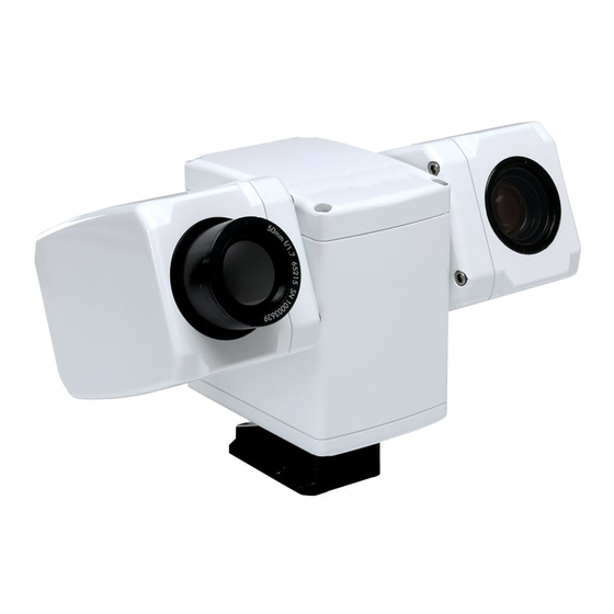
2.0 INTRODUCTION The PTZ-35 MS and PTZ-50 MS are high-resolution multi-sensor camera systems designed specifically for the security market. These small, pan/tilt systems feature a powerful thermal camera, with 35mm or 50mm lens, as well as a standard high resolution low-light video camera , integrated into a compact weather tight pan and tilt enclosure. -
Page 7: Advantages Of Thermal Imaging
PTZ-35 MS The PTZ-35 MS camera features a focal length of 35mm, providing a short to medium field of view of 20° and is well-suited for short range threat detection in all circumstances. It gives you a wide field of view, so you can cover a large area and keep excellent situational awareness. -
Page 8: Package Contents
Refer to the Shipping Check List that is shipped with each camera for a description of the parts and components that are included with the camera. If there is any discrepancy between the list and the contents of your shipment, please contact FLIR Systems Customer Support immediately using the contact information at the front of this manual. -
Page 9: Serial Communications
3.0 SERIAL COMMUNICATIONS The PTZ-35 MS and PTZ-50 MS cameras support serial communication for control of the camera motion and features. The camera is shipped with a graphical user interface (GUI) software that can be used to operate the camera and configure camera settings. The software is titled the ThermoVision SecurityHD User Interface, or commonly referred to as the SHD software. - Page 10 Figure 5: White Hot palette on left, Black Hot palette on right Contact FLIR Customer support for information on how to convert a camera from one standard to the other. 427-0116-00-10 Revision 130 Copyright © 2010 FLIR Systems, Inc.
-
Page 11: Quick-Start Information
You have now completed the basic steps for setup of the PTZ-35 MS / PTZ-50 MS. Follow the rest of this manual to learn how to control the camera and adjust the PTZ-35 MS / PTZ-50 MS system settings according to your preferences. -
Page 12: Thermovision Securityhd User Interface
The Communication Panel tab, shown in Figure 6, is located on the left- side of the About tab. The PTZ-35 MS / PTZ-50 MS can communicate at the 2400, 4800, 9600 & 57600 baud rates and both pan/tilt as well as camera control can be accessed. To access the device, simply choose the camera control switch and select the correct COM port that is connected to your PC. -
Page 13: Figure 8: Ptz-35 Ms / Ptz-50 Ms Communication Panel
It is recommended to use the fastest baud rate possible. • The GUI will have an easier time connecting to the PTZ-35 MS / PTZ-50 MS if the hardware is powered up prior to opening the software. •... -
Page 14: Pan/Tilt Panel
Pan/Tilt Panel The Pan/Tilt panel, shown in Figure 9, provides the ability to control the azimuth and elevation mechanism along with preset locations for the PTZ-35 MS / PTZ-50 MS. Pan/Tilt Drive: provides pan/tilt direction and positioning 1. Presets. The preset buttons allow the user to set/get 3 preset locations and determine the home location. -
Page 15: Infrared Panel
Video and AGC tab provides for basic image optimization along with camera control. The General tab allows for further camera control to set power-on defaults and get further camera data. The infrared camera commands for the PTZ-35 MS / PTZ-50 MS software interface are listed in section 10.0 Software Control Functions. -
Page 16: Figure 10: Ptz-35 Ms / Ptz-50 Ms Infrared Panel
Figure 10: PTZ-35 MS / PTZ-50 MS Infrared panel General: provides the user to save the default settings and monitor sensor or FPA temp 1. FPA Temperature. This command gets the FPA or sensor temperature and displays in degrees C. The FPA Temperature can also be monitored by depressing the “Monitor FPA Temp?”... -
Page 17: Dltv Panel
Figure 11: PTZ-35 MS / PTZ-50 MS Infrared panel DLTV Panel The DLTV panel contains the daylight camera settings as shown in the Figure 12. These commands provide the ability to control the daylight camera from the PC. Zoom: provides the user to control the daylight camera zoom and focus. -
Page 18: Manual Control Panel
2. Reset. This will reset the entry to all zeros. A list of commands is in Section 10.0 Software Control Functions. For a complete list of the commands refer to the PTZ-35 MS / PTZ-50 MS Software Interface Control Document or ICD 102-1270-151. 427-0116-00-10 Revision 130... -
Page 19: Figure 13: Ptz-35 Ms / Ptz-50 Ms Manual Control
Figure 13: PTZ-35 MS / PTZ-50 MS Manual Control 427-0116-00-10 Revision 130 Copyright © 2010 FLIR Systems, Inc. -
Page 20: Ptz-35 Ms / Ptz-50 Ms Physical Interface
6.0 PTZ-35 MS / PTZ-50 MS PHYSICAL INTERFACE 6.1 Dimension Drawings The following figures show a dimensional drawing of the PTZ-35 MS / PTZ-50 MS. Remember to firmly secure the unit and allow for device travel (pan and tilt). Pictures not to scale! -
Page 21: Figure 15: Ptz-35 Ms / Ptz-50 Ms Dimension Drawing With Hole Pattern
Pictures not to scale! Figure 15: PTZ-35 MS / PTZ-50 MS Dimension Drawing 427-0116-00-10 Revision 130 Copyright © 2010 FLIR Systems, Inc. -
Page 22: Integrated Interface Cable
6.2 Integrated Interface Cable The PTZ-35 MS / PTZ-50 MS camera uses an electrical-mechanical engagement system that requires only one integrated connection to the sensor. The standard interface cable is 12.5 meters (± 0.5 m) long and is terminated with MIL-C-26482 Series 1 connectors. - Page 23 Rx (+) RS-422 (COM3) Blu/Wht Rx (-) RS-422 (COM3) Wht/Grn Tx (+) RS-422 (COM3) Grn/Wht Tx (-) RS-422 (COM3) Yellow Power Green Orange Power Connector Outer Cable Shield Outer Cable Shield Connector Shell Shell 427-0116-00-10 Revision 130 Copyright © 2010 FLIR Systems, Inc.
-
Page 24: Breakout Connector Cable
6.3 Breakout Connector Cable The PTZ-35 MS / PTZ-50 MS camera also includes a breakout cable (as shown in Error! Reference source not found.) that connects to the integrated interface cable with single terminal connectors. The breakout cable has the MIL-C-26482 Series 1 Connector (Female) on one end and five pig-tail leads, described as follows: One lead is used for power and the pin outs are shown here. -
Page 25: Maintenance
Repeat several times with different pieces of tissue. 2. Repeat the same step using IPA instead of water. Drag the final piece of tissue over the lens several times to prevent pooling, which could leave a residue behind. 427-0116-00-10 Revision 130 Copyright © 2010 FLIR Systems, Inc. -
Page 26: Ptz-35 Ms / Ptz-50 Ms Specifications
8.0 PTZ-35 MS / PTZ-50 MS SPECIFICATIONS • Power/Weight : Input Voltage Range: 24 VDC ±10 % Sensor Weight w/o 3628 g (8 lbs) cable: • Pan/Tilt Specifications: Azimuth Elevation Motion Range (º) ± 200 ± 60 Angular Velocity (º/sec) - Page 27 Contacts Sockets Pins Shell Style Cable plug Cable plug Insert Position Keyring Keyring Orientation Normal Normal Finish Olive drab chromate over cadmium Note: These specifications are subject to change without notice. 427-0116-00-10 Revision 130 Copyright © 2010 FLIR Systems, Inc.
-
Page 28: Optional Joystick Display Unit
: If the camera moves or zooms without touching the joystick, this is called “drift”. Follow these instructions to correct the problem: 1. Recycle power without touching joystick during the flashing LED portion of the turn-on sequence. 427-0116-00-10 Revision 130 Copyright © 2010 FLIR Systems, Inc. -
Page 29: Figure 23: Operational Directions On Back Of Joystick Display Unit
Caution: The unit should be operated by a person other than the driver while vehicle is in use. When not in use, remove power jack from Joystick Display Unit. Figure 23: Operational Directions on back of Joystick Display Unit JDU Cable 427-0116-00-10 Revision 130 Copyright © 2010 FLIR Systems, Inc. -
Page 30: Software Control Functions
Flow Control None 10.2 IR Imager This section describes the structure of the commands of the IR imager on the PTZ-35 MS / PTZ-50 MS. Note that all data values are called out in hexadecimal. The command and response strings of the IR imager interface are of variable length, ranging from 10 bytes to 32 bytes. - Page 31 6E0000050000344B0000 6E0000050008B543(abcdefghijklmnop)0DF7 Software ab.cd.ef.gh FPGA ij.kl.mn.op Set FFC Mode Auto 6E00000B00020F0800000000 6E00000B00020F0800000000 Manual 6E00000B00020F0800011022 6E00000B00020F0800011022 Do FFC 6E00000C0000AADA0000 E-Zoom 6E00000F0002D3C800000000 6E00000F0002D3C800000000 6E00000F0002D3C800044084 6E00000F0002D3C800044084 Video Polarity White-Hot 6E0000100002BC9A00000000 6E0000100002BC9A00000000 Black-Hot 6E0000100002BC9A00011021 6E0000100002BC9A00011021 427-0116-00-10 Revision 130 Copyright © 2010 FLIR Systems, Inc.
- Page 32 Optimized Center 75% 6E00004C0008367FFF88FFD30078002DA5F2 6E00004C0008367FFF88FFD30078002DA5F2 Center 50% 6E00004C0008367FFFB0FFE20050001EE03A 6E00004C0008367FFFB0FFE20050001EE03A Center 25% 6E00004C0008367FFFD8FFF10028000F59BC 6E00004C0008367FFFD8FFF10028000F59BC Set Detail Enhancement 10 6E0000D30008627700003090106400043967 6E0000D30000E37F0000 20 6E0000D3000862770000309020640004158E 6E0000D30000E37F0001 30 6E0000D300086277000030903064000422C0 6E0000D30000E37F0002 Photon 6E0000020000B1DB0000 6E0000020000B1DB0000 Reboot Plateau Value 427-0116-00-10 Revision 130 Copyright © 2010 FLIR Systems, Inc.
- Page 33 6E00005500024AC7001452B5 30 6E00005500024AC7001EF3FF 6E00005500024AC7001EF3FF 40 6E00005500024AC70028A56A 6E00005500024AC70028A56A 50 6E00005500024AC700321611 6E00005500024AC700321611 60 6E00005500024AC7003CF7DF 6E00005500024AC7003CF7DF 70 6E00005500024AC700462802 6E00005500024AC700462802 80 6E00005500024AC700505AF5 6E00005500024AC700505AF5 90 6E00005500024AC7005AFBBF 6E00005500024AC7005AFBBF 100 6E00005500024AC700642C22 6E00005500024AC700642C22 110 6E00005500024AC7006E8D68 6E00005500024AC7006E8D68 125 6E00005500024AC7007DAF3A 6E00005500024AC7007DAF3A 427-0116-00-10 Revision 130 Copyright © 2010 FLIR Systems, Inc.
-
Page 34: Daylight Camera
10.3 Daylight Camera This section describes the structure of the commands of the daylight camera on the PTZ-35 MS / PTZ- 50 MS Sensor. Note that all data values are called out in hexadecimal. The command and response strings of the daylight camera interface are of variable length, ranging from of 5 to 32 bytes. The format for these command / response strings differs from the IR Imager in that the number of data bytes is not included in the string. -
Page 35: Pan/Tilt Mechanism
10.4 Pan/Tilt Mechanism This section describes the structure of the commands for the Pan/Tilt on the PTZ-35 MS / PTZ-50 MS Sensor. Note that all data values are called out in hexadecimal. The command and response strings of the Pan / Tilt Mechanism interface are of variable length, ranging from 5 to 32 bytes. The format for these command / response strings differs from the IR Imager in that the number of data bytes is not included in the string. -
Page 36: The Camera
90 41 FF 90 51 FF ZZ=Preset 1 to 64, 0x40=Position 64 0x00=invalid preset Note: Attempting to recall an invalid or cleared preset will result in random, slow motion movement of the camera. 427-0116-00-10 Revision 130 Copyright © 2010 FLIR Systems, Inc. -
Page 37: Pelco D Commands
0x4B General Tilt Tilt position position Set Tilt Position 0x4D General Zoom Zoom position position Set Zoom Position 0x4F General Extended Query Pan Position 0x51 (0x59) Query Tilt Position 0x53 Extended 427-0116-00-10 Revision 130 Copyright © 2010 FLIR Systems, Inc. - Page 38 Byte 4 Byte 5 Byte 6 Byte 7 Sync Command Address Command 2 Data 1 Data 2 Checksum Byte Desired Pelco 09/0B = AUX # Hex Sum of Bytes 2-6 Address On/Off 427-0116-00-10 Revision 130 Copyright © 2010 FLIR Systems, Inc.
-
Page 39: User Controls For Kbd300A
11.0 USER CONTROLS FOR KBD300A To start, type Pelco Address then CAM button Toggle Values (default to first Keystrokes PTZ-35 MS / PTZ-50 MS Function value) Near button Increments DLTV Focus closer Far button Increments DLTV Focus farther CW Joystick...
Need help?
Do you have a question about the PTZ-35 MS and is the answer not in the manual?
Questions and answers