FLIR PT series Installation Manual
Hide thumbs
Also See for PT series:
- Installation manual (27 pages) ,
- Installation manual (24 pages) ,
- Installation and user manual (58 pages)
Table of Contents
Advertisement
Advertisement
Table of Contents

Related Manuals for FLIR PT series


Summary of Contents for FLIR PT series
- Page 1 Installation Manual PT-Series...
- Page 2 © 2013 FLIR Commercial Systems, Inc. All rights reserved worldwide. No parts of this manual, in whole or in part, may be copied, photocopied, translated, or transmitted to any electronic medium or machine readable form without the prior written permission of FLIR Commercial Systems, Inc.
-
Page 3: Table Of Contents
Table of Contents Table of Contents PT-Series Camera Installation 1.1 Warnings and Cautions 1-1 1.2 References 1-1 1.3 Camera Overview 1-1 1.4 Installation Overview 1-2 1.4.1 Camera Connection Options 1-2 1.4.2 Supplied Components 1-3 1.4.3 Required Components 1-3 1.5 Location Considerations 1-3 1.5.1 Bench Testing 1-3 1.5.2 Prior to Cutting/Drilling Holes 1-4 1.5.3 Camera Mounting 1-4... - Page 4 Table of Contents 2.6.5 Security Settings 2-15 2.6.6 Configuration File 2-16 2.7 Thermal Imaging Overview 2-17 2.8 Troubleshooting Tips 2-19 2.9 General Errors 2-22 2.10 Restoring the Factory Settings 2-24 2.11 Setting the IP address on a Windows PC 2-25 Serial Address: Decimal To Binary Conversion 3.1 Address Conversion Table 3-1 427-0032-00-12, Version 170...
-
Page 5: Pt-Series Camera Installation
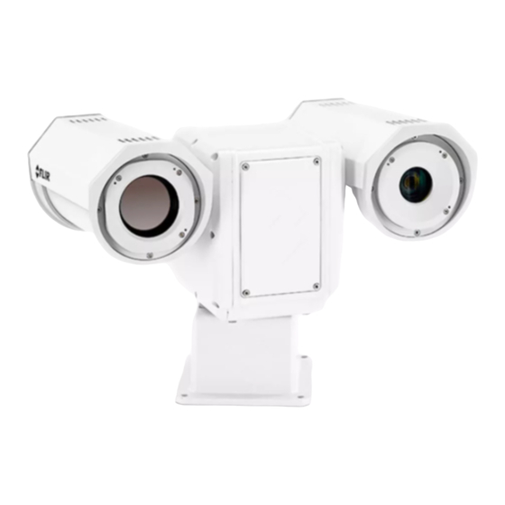
PT-Series camera. Nexus IP Camera Configuration Guide (FLIR Doc # 427-0030-00-28) • Available on the documentation CD or from the FLIR website, provides further details on using a web browser to configure the PT-Series camera. Camera Overview... -
Page 6: Installation Overview
PT-Series Camera Installation The PT-Series camera is both an analog and an IP camera. The video from the camera can be viewed over a traditional analog video network or it can be viewed by streaming it over an IP network using MPEG-4, M-JPEG and H.264 encoding. -
Page 7: Supplied Components
• Multi-sensor Pan/Tilt Camera Unit • Cable Glands and Spare Parts kit • FLIR Sensors Manager CD • PT-Series Camera Documentation Package 1.4.3 Required Components The installer will need to supply the following items; the lengths are specific to the installation. -
Page 8: Prior To Cutting/Drilling Holes
PT-Series Camera Installation For configuration and basic setup information using the onboard web server, refer to Basic Operation and Configuration on page 2-1. 1.5.2 Prior to Cutting/Drilling Holes When selecting a mounting location for the PT-Series camera, consider cable lengths and cable routing. -
Page 9: Removing The Back Cover
PT-Series Camera Installation Once the holes are drilled in the mounting surface, install four (4) stainless steel 5/16 or M8 bolts with stainless steel washers and lock washers through the base of the camera. Important Note Always use stainless steel washers on the four camera base mounting holes, especially in locations where the camera base is exposed to a damp or salt environment. -
Page 10: Cable Gland Seal Inserts
Ensure the camera is properly grounded. Typical to good grounding practices, the camera chassis ground should be provided using the lowest resistance path possible. FLIR requires using a grounding strap anchored to the grounding lug on the back plate of the camera housing and connected to the nearest earth-grounding point. - Page 11 PT-Series Camera Installation Serial and IP Communications Auxiliary Analog Video and Power Main Analog Video Male Male Ethernet Main Auxiliary Port Port RS232 3/4” NPT for Cable Gland or Conduit RS422 Chassis 20 AWG MAX 16 AWG Shielded Back Cover 16 AWG Shielded Local Serial...
-
Page 12: Ethernet Connection
Pelco D, RS-422 standard, 9600 baud rate, 8/1/none, and address 1. Note Typical Bosch systems operate using a biphase connection and the FLIR cameras do not accept biphase signals directly. It may be necessary to install a biphase converter in order to use the Bosch protocol. - Page 13 PT-Series Camera Installation The figure below shows the locations of dip switches SW102 and SW103. SW102 SW103 Switch Position Figure 1-4: PT-Series Camera Configuration If the Software Override DIP switch is set to the software position (as it is by default), all of the other DIP switches will be ignored, and configuration changes must be made through software.
- Page 14 PT-Series Camera Installation Other Serial Communication Parameters: The tables below defines the switch locations, bit numbering and on/off settings used in controlling the other serial communication parameters. Table 1-2: Dip Switch Settings—SW103 Settings Description Baud rate: This is the baud rate of the system user serial Bit 1 Bit 2 port.
-
Page 15: Pt-Series Camera Specifications
PT-Series Camera Installation PT-Series Camera Specifications THERMAL CAMERA SPECS Resolution 160 x 120 320 x 240 640 x 480 Detector Type Long-Life, Uncooled VO× Microbolometer Pixel Pitch 25 μm 25 μm 17 μm Focal Length (lens/model dependent) 9 mm, 13 mm, 19 mm 9 mm, 13 mm, 19 mm, 13 mm, 25 mm, 35 mm, 35 mm, 65 mm, 100 mm... - Page 16 PT-Series Camera Installation 427-0032-00-12, Version 170 Mar 2014 1-12...
-
Page 17: Basic Operation And Configuration
For a camera installed in an IP network, the camera will commonly be controlled over Ethernet by a PC or laptop running FLIR Sensors Manager (FSM) or a third-party Video Management System (VMS) software. FSM is an integral part of the Nexus architecture—it is a client program that communicates with the Nexus Server on the camera. -
Page 18: Serial Communications
(for example, any PC or device that will connect to the camera, any router or firewall that will carry the IP traffic, and so on). FLIR technical support can only provide limited support in this regard. -
Page 19: Basic Test And Configuration Steps
Basic Operation and Configuration Basic Test and Configuration Steps Assuming the existing network uses IP addresses that are unique and different than the default address on the camera, configuring the camera for IP communications generally involves the following steps: Step 1 Connect the Ethernet port to an IP network that is isolated from the existing camera network (for example, a standalone switch) Step 2... -
Page 20: Web Browser Interface
Basic Operation and Configuration the serial number, IP address, Pelco address, and the Baud rate. For example: S/N: 1234567 IP Addr: 192.168.250.116 PelcoD (Addr:1): 9600 SW Web Browser Interface Use a web browser to connect to the camera as described below, and confirm it is streaming video. Once the bench test is complete, use the web browser to make configuration changes as needed (for example, set the IP address to an address that is compatible with the existing network). -
Page 21: Camera Control And Status
The Live Video page will be displayed, with a live image from the camera on the left part of the screen. Next to the FLIR logo along the top of the screen are some menu choices, including Live Video (the red text indicates it is selected), Help and Log Off. -
Page 22: Web Control Panel
When the mouse cursor is positioned over a button, a screen tip is displayed which explains the function of the button. This same web interface is used with various FLIR thermal cameras; some are fixed mount cameras, such as the F-Series and FC-Series S cameras, and some have pan/tilt capabilities, such as the PT-Series and D-Series. - Page 23 It is possible to create customized camera functions through a “macro” interface which can be programmed through XML commands. For additional information contact FLIR Technical Support for information about the Nexus XML-Based Control Interfaces. When the Function button is selected, the keypad changes to a numeric keypad.
-
Page 24: Help
If it is necessary to contact FLIR Technical Support for assistance, it will be helpful to have the information from this page (such as Software Version) on hand. - Page 25 Panel. The FSM software can automatically discover FLIR cameras on the network. When the Discovery Panel is displayed, click Refresh. The FLIR camera will appear in the list of Discovered Sensors. The camera will be called “FLIR”, and the asterisk in parenthesis “(*)” indicates the camera has not been added to the list of Active Sensors on the right.
- Page 26 Basic Operation and Configuration Click on Video Wall 0 and confirm that video is streamed to the monitor and it is possible to control the camera using the pan/tilt/zoom controls in the Control Panel. For example, click on the zoom button (magnifying glass with +), and the video will zoom to 2X.
-
Page 27: Basic Camera Configuration
Basic Operation and Configuration Basic Camera Configuration The following procedures describe how to do the most common basic camera configuration steps, such as setting the camera IP address and hostname and changing the user passwords. To make these changes, it is necessary to login using the admin user account. Note In most installations, the only camera settings needed are available from the Live Video page (using Scene Presets or Polarity). -
Page 28: Maintenance Menu
Basic Operation and Configuration 2.6.2 Maintenance Menu Initially, when the Maintenance page is selected, the Server Status page is displayed. The page provides an indication of the current server status (either running or stopped) and buttons for starting or stopping the server or for rebooting the system. Note, In order to make some configuration changes through the Maintenance menu, it is necessary to save the changes, then stop and restart the server to make the changes take effect. -
Page 29: Lan Settings
Basic Operation and Configuration 2.6.3 LAN Settings The LAN Settings page can be used to set the hostname, default gateway, and IP address for the camera. The default IP Address mode is static; the mode can also be set to DHCP. Once the IP address of the camera is changed, the PC may no longer be on the same network and therefore may not be able to access the camera until the IP address on the PC is changed also. -
Page 30: Services (Date And Time Settings)
Basic Operation and Configuration 2.6.4 Services (Date and Time Settings) The Services page is used to configure the date and time settings. The date, time, and time zone can be obtained from an NTP server, or can be entered manually. If the NTP mode is selected, the NTP server information can be entered. -
Page 31: Security Settings
Basic Operation and Configuration 2.6.5 Security Settings To maintain security of your systems set passwords for each of the three login accounts. user —The user account can only use the Live Video screen and controls. expert —The expert account can use the Live Video screen and the camera Setup screen. admin —The admin account can use all screens After each password is set and confirmed, select the Save button at the bottom (it may be necessary to scroll down the page). -
Page 32: Configuration File
Basic Operation and Configuration It is also possible to limit access to the camera from a client program (such as FSM) by IP address. To do so, in the Maintenance menu select Sensor, then Networking. Set the “Allow anonymous clients” parameter to No, and then add in the allowed addresses in the Remote Clients list and click Save. -
Page 33: Thermal Imaging Overview
Basic Operation and Configuration Thermal Imaging Overview When power is applied to the PT-Series camera, a FLIR splash screen is displayed for less than two seconds, and then the camera outputs the live video image. No operator action or intervention is required and no configuration of the camera is necessary. - Page 34 Basic Operation and Configuration They are perfect for a wide variety of applications including transportation, maritime, security, fire fighting, and medical applications. The cameras often provide improved daytime viewing in environments where traditional video camera performance suffers, such as in shadows or backlit scenes.
-
Page 35: Troubleshooting Tips
If the camera still does not produce an image, contact the FLIR dealer or reseller who provided the camera, or contact FLIR directly (contact information is provided on the rear cover of this manual). - Page 36 FSM program. Typically when FSM runs for the first time, a pop-up notification may ask for permission to allow the FLIR Sensors Manager (fsm.exe) to communicate on the network. Select the check boxes (domain/private/public) that are appropriate for your network.
- Page 37 Basic Operation and Configuration In the Sensors Panel, if the camera is the active sensor, there will be an “(Active)” notification next to the name of the camera. Only one camera or sensor can be active at a time. To make the camera active, right click on the icon to the left of the camera name and select “Set Active”, or simply double-click on the icon.
-
Page 38: General Errors
When displaying video with FSM for the first time, the Windows Personal Firewall may ask for permission to allow the FLIR Video Player (vp.exe) to communicate on the network. Select the check boxes (domain/private/public) that are appropriate for your network. - Page 39 Basic Operation and Configuration Cable characteristics are determined by a number of factors (core material, dielectric material and shield construction, among others) and must be carefully matched to the specific application. Moreover, the transmission characteristics of the cable will be influenced by the physical environment through which the cable is run and the method of installation.
-
Page 40: Restoring The Factory Settings
Basic Operation and Configuration 2.10 Restoring the Factory Settings The camera comes configured from the factory with default settings for the IP address (192.168.250.116), the login passwords, and all of the other configuration parameters (stored in a file called server.ini). In some cases, it may be necessary to restore the settings of the camera to the original factory settings. -
Page 41: Setting The Ip Address On A Windows Pc
Basic Operation and Configuration After the camera boots up, confirm the startup information is displayed on the analog monitor after approximately 90 seconds. For example: S/N: 1234567 IP Addr: 192.168.250.116 PelcoD (Addr:1): 9600 SW 2.11 Setting the IP address on a Windows PC To set the computer IP address in Windows, first connect the PC to a switch, or connect it to the camera and ensure the camera has power. - Page 42 Basic Operation and Configuration Step 2 Click to select the Local Area Connection then click Properties, as shown at the right. Click Properties Step 3 Select Internet Protocol Version 4 (TCP/IPv4) as shown. Then click Properties. Click to select Click Properties 2-26 427-0032-00-12 Version 170 Mar 2014...
- Page 43 Basic Operation and Configuration Step 4 Select Use the following IP address, then enter 192.168.250.xxx, where xxx is any number between 1-255, other than 116 (the camera default). Step 5 Set the Subnet mask to 255.255.255.0, then click OK. 427-0032-00-12 Version 170 Mar 2014 2-27...
- Page 44 Basic Operation and Configuration 427-0032-00-12, Version 170 Mar 2014 2-28...
-
Page 45: Address Conversion Table
Serial Address: Decimal To Binary Conversion Note, the order of the switches 1-8 is the reverse of the binary digits. For example, for address 1 the binary equivalent is 00000001 and the left-most switch (switch1) is on. Address Conversion Table Address Sw 2 Sw 3... - Page 46 Serial Address: Decimal To Binary Conversion 00011100 01011100 10011100 11011100 00011101 01011101 10011101 11011101 00011110 01011110 10011110 11011110 00011111 01011111 10011111 11011111 00100000 01100000 10100000 11100000 00100001 01100001 10100001 11100001 00100010 01100010 10100010 11100010 00100011 01100011 10100011 11100011 00100100 01100100 10100100 11100100 00100101...
- Page 47 Serial Address: Decimal To Binary Conversion 427-0032-00-12, version 170 Mar 2014...
- Page 48 FLIR Systems, Inc. 70 Castilian Drive Goleta, CA 93117 PH: + 1 805.964.9797 PH: + 1 877.773.3547 (Sales) PH: + 1 888.747.3547 (Support) FX: + 1 805.685.2711 www.flir.com Corporate Headquarters FLIR Systems, Inc. 27700 SW Parkway Ave. Wilsonville, OR 97070 PH: +1 503.498.3547...
Need help?
Do you have a question about the PT series and is the answer not in the manual?
Questions and answers