FLIR PT Series Installation And User Manual
Hide thumbs
Also See for PT Series:
- Installation manual (48 pages) ,
- Installation manual (27 pages) ,
- Installation manual (24 pages)

Related Manuals for FLIR PT Series


Summary of Contents for FLIR PT Series
- Page 1 427-0075-01-12 Revision 140 October 2019 This document does not contain any export-controlled information.
- Page 2 427-0075-01-12 Revision 140 October 2019 This document does not contain any export-controlled information.
-
Page 3: Table Of Contents
2.1.1 Serial and/or IP Communications ...................21 2.1.2 Server Configuration ......................21 2.2 Camera Bench Test .........................21 2.2.1 Set IP Address using the FLIR Discovery Network Assistant (DNA) ......22 2.3 Log into the Camera Web Page ....................23 2.3.1 Live Video Page ......................24 2.3.2 Camera Control and Status ....................25... -
Page 4: Pt-Series Hd Camera Installation
This manual describes the installation of the PT-Series HD cameras. If help is needed during the installation process, please refer to for support. All installers and integrators are encouraged to take advantage of the training offered by FLIR; visit for more information. This manual includes the following topics: •... -
Page 5: Camera Overview
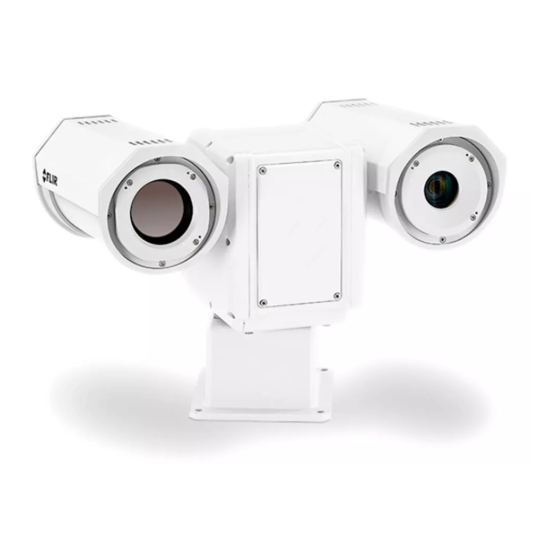
PT-Series HD Camera Installation Camera Overview The PT-Series HD camera is both an analog and an IP camera. The video from the camera can be viewed over a traditional analog video network or it can be viewed by streaming it over an IP network using MJPEG or H.264 encoding. -
Page 6: Serial Communications Overview
PT-Series HD Camera Installation Network Security The camera supports IEEE 802.1x authentication when connected to a network supporting the following requirements: • Network device (Authenticator) such as an Ethernet switch configured with 802.1x • Authentication server supporting either TLS Refer to for information on how to configure the LAN settings. -
Page 7: Location Considerations
Proper grounding (bonding) to earth ground 1.5.1 Galvanic Isolation The Galvanic Isolation Kit (FLIR PN 4204960) is for use with all PT-Series HD cameras. The isolation plate and nylon shoulder or flat washers provide electrical isolation between the stainless 427-0075-01-12 Revision 140 October 2019 This document does not contain any export-controlled information. -
Page 8: Earth Ground Connection
PT-Series HD Camera Installation steel fasteners and the aluminum camera base, and electrically isolates the complete PT-Series HD camera from the customer mount. Galvanic isolation is critical in preventing corrosion. Proper installation of galvanic isolation pad and washers is important for long product life. Refer to for specific instructions. -
Page 9: Installation Of Camera And Galvanic Isolation Kit
PT-Series HD Camera Installation PT-Series HD cameras must be mounted upright on top of the mounting surface, with the base below the camera. The unit should not be hung upside down. Not to scale 4X Ø.354 THRU All dimensions in inches Pan volume minimum Ø25.5 2X 3.17 ±... - Page 10 PT-Series HD Camera Installation • Once the mounting location has been selected, verify both sides of the mounting surface are accessible and free of utility service lines or other obstructions. • Use stainless steel hardware to fasten mounts to outdoor surfaces. •...
- Page 11 PT-Series HD Camera Installation Step 5 Ensure the camera is properly grounded. FLIR requires using a 14 AWG to 16 AWG grounding strap anchored to the ground lug on the back plate of the camera housing and then terminated to the nearest earth-grounding point.
-
Page 12: Camera Connections
PT-Series HD Camera Installation Camera Connections 1.6.1 Remove the Back Cover Use a 2.5 mm hex key to loosen the captive screws and remove the cover, exposing the connections at the back of the camera. There is a grounding wire connected between the case and the back cover IP Network Analog Video... -
Page 13: Connecting Power
Ensure the camera is properly grounded. Typical to good grounding practices, the camera chassis ground should be provided using the lowest resistance path possible. FLIR requires using a grounding strap anchored to the grounding lug on the back plate of the camera housing and connected to the nearest earth-grounding point. -
Page 14: Video Connections
Pelco D, RS-422 standard, 9600 baud rate, 8/1/none, and address 1. Note Typical Bosch systems operate using a biphase connection. FLIR cameras do not accept biphase signals directly. It may be necessary to install a biphase converter in order to use the Bosch protocol. -
Page 15: Serial Communications Settings - Hardware Dip Switches
PT-Series HD Camera Installation Note The serial communications parameters for the PT-Series HD camera are set or modified either via hardware DIP switch settings or via software, through a web browser interface. A single DIP switch (SW103-9), Software Override determines whether the configuration comes from the hardware DIP switches or the software settings. - Page 16 PT-Series HD Camera Installation Table 1-2: Dip Switch Address/ID Settings—SW101 Other Serial Communication Parameters: The tables below defines the switch locations, bit numbering and on/off settings used in controlling the other serial communication parameters. Table 1-3: Dip Switch Settings—SW103 Settings Description Baud rate: Bit 1...
-
Page 17: Back Cover Gasket
PT-Series HD Camera Installation 1.6.7 Back Cover Gasket When preparing to re-attach the back cover, make sure that the gasket rests securely in the groove so that attaching the cover does not cut or otherwise damage the gasket. The picture below shows the black gasket properly in place. - Page 18 If non-standard cable diameters are used, it may be necessary to locate or fabricate the appropriate insert to fit the desired cable. FLIR Systems, Inc. does not provide cable gland inserts other than what is supplied with the system. Heater...
-
Page 19: Series Hd Camera Specifications
PT-Series HD Camera Installation PT-Series HD Camera Specifications Uncooled Thermal Camera Model Focal Length Optical Characteristics Visible Camera Cooled Thermal Camera PT-602CZ HD Compliance and Certifications 427-0075-01-12 Revision 140 October 2019 This document does not contain any export-controlled information. - Page 20 PT-Series HD Camera Installation Video System Integration Pan/Tilt General Environmental Method 514.6, Procedure 1b Power consumption is independent of the input voltage when the heater is off. The power drawn by the heaters in- creases with the input voltage to a maximum at 30 Volts. 427-0075-01-12 Revision 140 October 2019 This document does not contain any export-controlled information.
-
Page 21: Ip Camera, Onvif Profile S Compliant
The communications protocol used is an open, standards-based protocol that allows the server to communicate with a video management client, such as FLIR Latitude or with a third-party VMS client, including systems that are compatible with ONVIF Profile S. These clients can be used to control the camera and stream video during day-to-day operations. -
Page 22: Set Ip Address Using The Flir Discovery Network Assistant (Dna)
Once the camera is connected to a network and powered on, set camera network parameters using the FLIR Discovery Network Assistant (DNA) software, perform a bench test by using a web browser to view the video and control the camera, or view video in the local Network Video Management System (for example, FLIR Latitude). -
Page 23: Log Into The Camera Web Page
Basic Operation and Configuration Step 4 Step 5 Double-click the camera in DNA’s Discovery List to open the camera’s web server Login page in a web browser, or point a web browser to the camera’s IP address. Step 6 Using a web browser, configure the camera settings, such as camera date/ time, and other parameters, so the camera is compatible with the existing... -
Page 24: Live Video Page
NVR. If the live video is not displayed, refer to Help menu displays software version information. If it is necessary to contact FLIR Technical Support for assistance, it will be helpful to have the information from this page on hand. For information about the camera including hardware part numbers and serial numbers refer to the Maintenance >... -
Page 25: Camera Control And Status
Save snapshot Video stream This same web interface is used with various FLIR thermal cameras, some of which have different capabilities. As a result, different buttons in the control panel will appear for different FLIR cameras. not present for PT-602CZ HD Go to Preset position. - Page 26 Basic Operation and Configuration The functions of the buttons appearing for the PT-Series HD cameras are described below: Zoom In/Zoom Out These buttons zoom the active camera (IR or daylight). On cameras with optical zoom lenses, digital zoom or E-Zoom extends the ability to zoom in beyond the optical zoom range, but at the expense of resolution.
-
Page 27: Camera Configuration
Basic Operation and Configuration Autofocus This button causes the DLTV camera to toggle the autofocus mode. Clicking the button a second time reinstates the autofocus mode and causes an autofocus operation. This button causes the IR camera with a zoom lens to perform a one-time autofocus operation. -
Page 28: Expert And Admin Accounts
Basic Operation and Configuration Note In most installations, the only camera settings needed are available from the Live Video page (using Scene Presets or Polarity). Use caution when modifying the camera settings described in this section. Some settings may adversely affect the thermal image over time or may completely disable the camera or the network interface. -
Page 29: Setup Menu
DLTV camera, Video 2 and Video 3 are sourced from the IR thermal imager. All video streams are available for viewing from a client program such as FLIR Latitude, a stand-alone video player, or a third-party VMS (including ONVIF systems). - Page 30 Basic Operation and Configuration To modify parameters that affect a particular IP Video stream from the camera, select the appropriate link (for example, The default parameters provide high-quality full frame-rate video streams with reasonable bandwidth usage. In general, for most installations it will not be necessary to modify the default parameters. In some cases, such as when a video stream is sent over a wireless network, it may be useful to adjust the frame rate of the video stream to reduce the required bandwidth.
- Page 31 Basic Operation and Configuration The parameters in the Encoding section will have a significant impact on the quality and bandwidth requirements of the video stream. In general it is recommended that the default values are used initially, and then individual parameters can be modified and tested incrementally to determine if the bandwidth and quality requirements are met.
- Page 32 Basic Operation and Configuration For enhanced security, RTSP authentication can be enabled. There are some challenges with streaming video over an IP network, when compared to applications which are less time-critical, such as email and web browsing. There are requirements which must be fulfilled to ensure satisfactory video quality in professional security environments.
- Page 33 Basic Operation and Configuration IR > AGC The AGC parameters affect how the overall IR video image appears. Using the AGC button on the Live Video page (refer to ), toggle through five AGC algorithms. The default algorithms are suitable for most installations, but each selection allows a combination of further adjustments that may provide a more appealing image, depending on personal preferences.
-
Page 34: Maintenance Menu
Basic Operation and Configuration Surveillance > Scan List To setup Presets: position camera, select Preset ID Click Set Surveillance > Auto Scan To start Auto Scan: select width and speed, then select Start Set Autoscan parameters: select speed, select limits, click Save Relative Auto Scan (Surveillance mode) will scan the scene starting with the current position of the camera. - Page 35 Basic Operation and Configuration Server > LAN Settings page can be used to set the hostname, default gateway, and IP address for the camera. Scroll down to see settings for Domain Name System (DNS) server and 802.1x Security. IP Address When set to DHCP, if the network does not have a DHCP server, the PT-Series HD camera will default to an IP address of 192.168.0.250.
- Page 36 Basic Operation and Configuration To configure 802.1x security on the LAN using TLS authentication: Step 1 On the LAN Settings page, scroll down to 802.1X Security. Step 2 Select the Use 802.1x security checkbox. Step 3 From the Authentication drop-down menu, select TLS.
- Page 37 Basic Operation and Configuration Server > Services > Date and Time The date, time, and time zone can be obtained from an NTP server, or can be entered manually. If the NTP mode is selected, the NTP server information can be entered. The NTP server address can be entered as a static address or can be obtained via DHCP.
- Page 38 Basic Operation and Configuration Server > Services > Systems Use the page to set up a connection to a mail server to send outgoing email notifications. If the email server is on a different network, ensure the IP default gateway and DNS servers are configured in the LAN Settings;...
- Page 39 Basic Operation and Configuration Server > Services > TLS Config The settings on this page enable secure, encrypted communication between clients and the camera; for example, when your web browser accesses the camera’s web interface. Note The camera also supports TLS authentication over the camera’s LAN. For information about configuring TLS authentication for LAN communication, see By default, TLS is disabled.
- Page 40 Basic Operation and Configuration To generate and install a self-signed certificate: Step 1 Under Generate Certificate, for Method, select Self-Signed. Step 1 Enter information such as country code, city name, and organization name. Step 2 Scroll to the bottom of the page and click Generate Certificate. Step 3 Allow 15 seconds for the camera to generate the certificate, at which point a confirmation appears.
- Page 41 Basic Operation and Configuration Certificate information appears at the bottom of the TLS Config page, under Certificate Information: To enable and configure TLS: Step 1 Under TLS Configuration, for Enabled, select Yes. Step 2 Select whether to redirect HTTP requests to HTTPS.
- Page 42 Basic Operation and Configuration After making configuration changes, it is necessary to save the changes to the server (there is a Save button at the bottom of each configuration page). The configuration changes do not take effect immediately. Generally, it is also necessary to stop and restart the server for the changes to become effective.
- Page 43 Basic Operation and Configuration Restrict web configuration Add IP address The admin login can limit which computers have access to the web browser interface. Simply add a computer’s IP address and click Add. After all the allowed IP addresses are entered, click Save to save the changes.
- Page 44 Basic Operation and Configuration Firewall settings For enhanced security, a firewall can be enabled (by scrolling down on the Security Options page). With the firewall enabled, you can open the following services and their default ports by selecting Enabled: • RTSP •...
- Page 45 Basic Operation and Configuration Sensor > Communications > Serial Remote Bosch settings Pelco-D settings Select protocol Save Toggle Server (Stop/Start) Sensor > Communications > VMS Remote The VMS Remote page provides communication interfaces for devices that connect to the camera. Authentication when enabled uses the same passwords set from the Server Security Options page.
- Page 46 An ONVIF-compliant VMS can be used to control a FLIR camera. Refer to the VMS documentation to determine what parameters are needed. By default, the camera is configured with a VMS Remote interface with ONVIF 2.0 parameters (Profile S).
- Page 47 By default, four video streams are enabled for the camera: Video 0, Video 1, Video 2, and Video 3. The streams are available for viewing from a client program such as FLIR Latitude, a stand-alone video player, or a third-party VMS including ONVIF systems. By default, Video 0 and Video 1 are from the visible camera, while Video 2 and Video 3 are from the IR sensor.
- Page 48 Basic Operation and Configuration To modify parameters that affect a particular IP Video stream from the camera, select the appropriate link at the top of the page (for example, The default RTP Settings for connecting to an IP video stream from the PT-Series HD are shown in the illustration.
- Page 49 Protocol (RTCP) and Real Time Streaming Protocol (RTSP). In the background, a “negotiation” takes place to establish a session between the client (such as FLIR Latitude, a third party VMS, or video player) and the camera. The ports which form a session are negotiated using a protocol such as RTSP.
-
Page 50: Files Menu
Basic Operation and Configuration 2.4.4 Files Menu The administrative actions for accessing, updating, and transferring files are accessed through the menu on the left side of the page. Selected actions from the Firmware, , and Log pages are described below. Stop server Files >... - Page 51 Basic Operation and Configuration is the configuration script file in a scrollable window. This can be useful if help is ever needed from a support engineer. In the Backup & Recovery section, click the Restore link associated with the factory.defaults configuration to restore the camera to its factory settings.
-
Page 52: Thermal Imaging Overview
Basic Operation and Configuration Files > Log > Field Support Log Scroll down and select the button under Field Support Log to download a zip file to the computer for field service evaluation. Thermal Imaging Overview PT-602CZ HD Only—When power is applied to the PT-602CZ HD camera, a compact integral Stirling cooler (also known as a cryocooler) starts automatically. -
Page 53: Troubleshooting Tips
RCA connection inside the camera and determine if it produces an image. If the camera still does not produce an image, contact the FLIR dealer or reseller who provided the camera, or contact FLIR directly (contact information is provided on the rear cover of this manual). - Page 54 When displaying video with FLIR Latitude or a VMS for the first time, the Windows Personal Firewall may ask for permission to allow the video player to communicate on the network. Select the check boxes (domain/private/public) that are appropriate for the network.
- Page 55 Basic Operation and Configuration Check cable connector terminations. Inferior quality connections may use multiple adapters which can cause unacceptable noise. Use a high-quality video distribution amplifier when splitting the signal to multiple monitors. Image too dark or too light: By default the PT-Series HD thermal camera uses an Automatic Gain Control (AGC) setting that has proven to be superior for most applications, and the camera will respond to varying conditions automatically.
-
Page 56: Serial Address: Decimal To Binary Conversion
Serial Address: Decimal To Binary Conversion Note, the order of the switches 1-8 is the reverse of the binary digits. For example, for address 1 the binary equivalent is 00000001 and the left-most switch (switch1) is on. Address Conversion Table Address Sw 2 Sw 3... - Page 57 Serial Address: Decimal To Binary Conversion 427-0075-01-12 Revision 140 October 2019 This document does not contain any export-controlled information.
- Page 58 FLIR Systems, Inc. 6769 Hollister Ave Goleta, CA 93117 Corporate Headquarters FLIR Systems, Inc. 27700 SW Parkway Ave. Wilsonville, OR 97070 Support: Document: 427-0075-01-12 Revision: 140 Date: October 2019 This document does not contain any export-controlled information.
Need help?
Do you have a question about the PT Series and is the answer not in the manual?
Questions and answers