FLIR PT-Series Installation Manual
Hide thumbs
Also See for PT-Series:
- Installation manual (48 pages) ,
- Installation manual (24 pages) ,
- Installation and user manual (58 pages)
Table of Contents
Advertisement
Quick Links
Download this manual
See also:
Installation Manual
FLIR Commercial Systems, Inc.
Document Number: 427-0032-00-12
Version: 150
Issue Date: January 2012
This document is controlled to FLIR Technology Level EAR 1. The information contained in this document is proprietary and/or restricted and
pertains to a dual use product controlled for export by the Export Administration Regulations (EAR). This document and data disclosed herein or
herewith is not to be reproduced, used, or disclosed in whole or in part to anyone without the written permission of FLIR Systems, Inc. Diversion
contrary to US law is prohibited. US Department of Commerce authorization is not required prior to export or transfer to foreign persons, parties,
or uses otherwise prohibited.
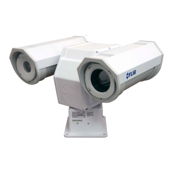
PT-Series Camera
Installation Manual
70 Castilian Drive
Goleta, CA 93117
Phone: 888.747.FLIR (888.747.3547)
International: +1.805.964.9797
www.flir.com
Advertisement
Table of Contents

Related Manuals for FLIR PT-Series


Summary of Contents for FLIR PT-Series
- Page 1 Export Administration Regulations (EAR). This document and data disclosed herein or herewith is not to be reproduced, used, or disclosed in whole or in part to anyone without the written permission of FLIR Systems, Inc. Diversion contrary to US law is prohibited.
- Page 2 PT-Series Installation Manual © FLIR Commercial Systems, Inc., 2012. All rights reserved worldwide. No parts of this manual, in whole or in part, may be copied, photocopied, translated, or transmitted to any electronic medium or machine readable form without the prior written permission of FLIR Commercial Systems, Inc.
-
Page 3: Table Of Contents
2.4.3 Digital Video Configuration—Video IR and Video DLTV ....... 2-7 2.4.4 Analog Video Configuration—Video Matrix ........2-7 2.4.5 Configuration File ............... 2-8 2.4.6 LAN Settings ................2-8 A Mechanical ICD Reference Sheet 1 PT-Series Camera Mechanical Interface Control Document ....A-3 427-0032-00-12, version 150 January 2012... - Page 4 Table of Contents PT-Series Installation Manual 427-0032-00-12, version 150...
-
Page 5: Pt-Series Camera Installation
PT-Series Camera Installation This manual describes the installation of the PT-Series cameras. If you need help during the installation process, please call to speak with our support experts (877-773-3547). This manual includes the following topics: • Installation Overview • Mounting the camera and its components •... -
Page 6: Installation Overview
The mount must support up to 45 lbs. (20 KG). The PT-Series camera is both an analog and an IP camera. The video from the camera can be viewed over a traditional analog video network or it can be viewed by streaming it over an IP net- work using MPEG-4, M-JPEG and H.264 encoding. -
Page 7: Location Considerations
Ensure that cable distances do not exceed the Referenced Standard specifications and adhere to all local and Industry Standards, Codes, and Best Practices. Not to scale All dimensions in inches Maximum exclusion cylinder (Ø25.5” x 17.4” high) Figure 1-2: PT-Series Pan and Tilt Exclusion Zone 427-0032-00-12, version 150 January 2012... -
Page 8: Camera Mounting
PT-Series cameras must be mounted upright on top of the mounting surface, with the base below the camera. The unit should not be hung upside down. The PT-Series camera can be secured to the mount with four 5/16 or M8 bolts, as shown below. -
Page 9: Prior To Cutting/Drilling Holes
PT-Series Installation Manual 1—PT-Series Camera Installation Prior to Cutting/Drilling Holes When selecting a mounting location for the PT-Series camera, consider cable lengths and cable routing. Ensure the cables are long enough given the proposed mounting locations and cable routing requirements. -
Page 10: Cable Gland Seal Inserts
Cable Gland Seal Inserts Ground Ethernet gland seal plugs The PT-Series camera comes with two 3/4” NPT cable glands, each with a three hole gland seal insert. Cables may be between 0.23" to 0.29" od. Up to six cables may be installed. -
Page 11: Electrical Connections And Schematics
Gland B Camera End Gland A Camera End IP Network Analog Video Analog Visible Video (monitoring output only) Not used Serial Connector for local control Camera Power Heater Power Analog Infrared Video Figure 1-4: PT-Series Camera Connections 427-0032-00-12, version 150 January 2012... -
Page 12: Connecting Power
PT-Series Installation Manual Connecting power The camera itself does not have an on/off switch. Generally the PT-Series camera will be connected to a circuit breaker and the circuit breaker will be used to apply or remove power to the camera. If power is supplied to it, the camera will be in one of two modes: Booting Up or Powered On. -
Page 13: Serial Connections
SW103 Switch Position Figure 1-5: PT-Series Camera Configuration Pelco Address: This is the address of the system when configured as a Pelco device. The available range of values is from decimal 0 to 255. Table 1-1: Dip Switch Address/ID Settings—SW102... - Page 14 1—PT-Series Camera Installation PT-Series Installation Manual Other Serial Communication Parameters. The tables below defines the switch locations, bit numbering and on/off settings. Table 1-2: Dip Switch Settings—SW103 Settings Description Baud rate: This is the baud rate of the system user...
-
Page 15: Pt-Series Camera Specifications
PT-Series Installation Manual 1—PT-Series Camera Installation 1.15 PT-Series Camera Specifications THERMAL CAMERA SPECS Resolution 160 x 120 320 x 240 640 x 480 Detector Type Long-Life, Uncooled VO× Microbolometer Pixel Pitch 25 μm 25 μm 17 μm Focal Length (lens/model dependent) - Page 16 1—PT-Series Camera Installation PT-Series Installation Manual 1-12 January 2012 427-0032-00-12, version 150...
-
Page 17: Verify Camera Operation
IP Addr: 192.168.250.116 PelcoD (Addr:1): 9600 SW Verify IP Communications As shipped from the factory, the PT-Series camera has an IP address of 192.168.250.116 with a netmask of 255.255.255.0. Step 1 Configure a laptop or PC with another IP address from this network (for example, 192.168.250.1). -
Page 18: Using Flir Sensors Manager (Fsm)
Using FLIR Sensors Manager (FSM) The following provides a brief description of how to use FSM to control a camera and stream video from the camera. For more detailed information on how to use FSM, refer to the FLIR Sensors Manager User Manual. - Page 19 Step 4 When the Discovery Panel is displayed, click Refresh. The FLIR camera will appear in the list of Discovered Servers. The camera will be called “flir”, and the asterisk in parenthesis “(*)” indicates the camera has not been added to the list of Active Servers on the right.
- Page 20 The menu on the left allows you to select various configuration web pages in order to set the camera parameters. See “PT-Series Configuration” on page 2-5. January 2012 427-0032-00-12, version 150...
-
Page 21: Pt-Series Configuration
If you need to contact FLIR for support, this information will be useful to the support engineer. Use the Menu entries at the left of the screen shown in Figure 2-1 to configure the PT-Series camera. -
Page 22: Serial Remote Menu
2—Verify Camera Operation PT-Series Installation Manual 2.4.2 Serial Remote Menu The settings you make in this screen will become active when the software override DIP switch is set to Off (the default) allowing software settings to control the camera. Refer to paragraph 1.14 “Setting Configuration Dip Switches”... -
Page 23: Digital Video Configuration-Video Ir And Video Dltv
2.4.4 Analog Video Configuration—Video Matrix Click Video Matrix The screen at the right will be displayed. The PT-Series camera provides two analog video ports: Main and Auxiliary. • You can select the source of each port from this screen. • Set the Device type (set Device ID) for each source. -
Page 24: Configuration File
2—Verify Camera Operation PT-Series Installation Manual 2.4.5 Configuration File Step 1 Click Configuration File. The screen at the right will be displayed. Shown at the top of the screen is the .ini file in a scrollable window. This can help if you ever need help from a support engineer. -
Page 25: A Mechanical Icd Reference
Series cameras. These documents are provided for reference only. You should consult your local sales representative or application engineer to obtain current ICD information. Also, the PT-Series Thermal Imaging Camera Core Data Sheet available from the website contains important mechanical interface data as well. - Page 26 A—Mechanical ICD Reference PT-Series Installation Manual January 2012 427-0032-00-12, version 150...
- Page 27 THE INFORMATION CONTAINED IN THIS DOCUMENT PERTAINS TO A DUAL USE PRODUCT CONTROLLED FOR EXPORT BY THE EXPORT ADMINISTRATION REGULATIONS (EAR). FLIR TRADE SECRETS CONTAINED HEREIN ARE SUBJECT TO DISCLOSURE RESTRICTIONS AS A MATTER OF LAW. DIVERSION CONTRARY TO US LAW IS PROHIBITED.
Need help?
Do you have a question about the PT-Series and is the answer not in the manual?
Questions and answers