
Related Manuals for Furuno BR-500


Summary of Contents for Furuno BR-500
- Page 1 OPERATOR'S MANUAL BRIDGE NAVIGATIONAL WATCH ALARM SYSTEM (BNWAS) BR-500 MODEL www.furuno.co.jp...
- Page 2 : +81-(0)798-65-4200 A : MAR 2011 Printed in Japan All rights reserved. A2 : APR . 14, 2011 Pub. No. OME-44610-A2 *00017461810* *00017461810* (DAMI ) BR-500 *00017461810* *00017461810* * 0 0 0 1 7 4 6 1 8 1 0 *...
-
Page 3: Important Notices
How to discard a used battery Some FURUNO products have a battery(ies). To see if your product has a battery, see the chapter on Maintenance. Follow the instructions below if a battery is used. Tape the + and - terminals of battery before disposal to prevent fire, heat generation caused by short circuit. -
Page 4: Safety Instructions
SAFETY INSTRUCTIONS Read these safety instructions before you operate or install the equipment. Indicates a condition that can cause death or serious injury if WARNING not avoided. Indicates a condition that can cause minor or moderate injury if CAUTION not avoided. Warning, Caution Prohibitive Action Mandatory Action... - Page 5 SAFETY INSTRUCTIONS CAUTION WARNING Do not open the equipment unless Securely ground (protection earth) authorized. the equipment. This equipment uses high voltage which Ineffective ground can cause electrical can cause electrical shock if mishandled. shock. Turn off power at switchboard before Follow the compass safe distances starting the installation.
-
Page 6: Table Of Contents
TABLE OF CONTENTS FOREWORD ........................vi SYSTEM CONFIGURATION ..................viii MAIN ALARM PANEL ...................1-1 1.1 Controls........................1-1 1.2 How to Turn the System On/Off ................. 1-1 1.3 BNWAS Display ......................1-3 1.4 How to Adjust the LCD Brilliance, Key Backlighting........... 1-4 1.5 How to Select the Backup Officer ................1-5 1.6 Mode .......................... - Page 7 TABLE OF CONTENTS 4.10 Menu Settings......................4-16 4.10.1 Administrator Menu ..................4-16 4.10.2 Service Menu ....................4-20 4.11 I/O Sentence Information..................4-22 APPENDIX 1 MENU TREE, ABBREVIATIONS, JIS CABLE GUIDE ......AP-1 SPECIFICATIONS ..................... SP-1 INDEX ......................... IN-1...
-
Page 8: Foreword
Features The BR-500 monitors the Officer of the Watch’s (OOW) presence on the bridge to prevent mari- time casualties. The system sends an alarm to the quarters of the backup officer if the OOW fails to respond to the active alarm or emergency call. - Page 9 The Motion Detector can be affected by sunlight. Install it in a place well away from sunlight. Alarm ACK signal The BR-500 receives the Alarm ACK signal in contact signal format only. It cannot receive the sig- nal in serial format.
-
Page 10: System Configuration
SYSTEM CONFIGURATION MAIN ALARM PANEL BR-510 Operator Fitness IN (4 lines) CABIN PANEL BR-540 (Max. 12) Backup Navigator IN (1 line) TIMER RESET PANEL BR-530 PROCESSOR UNIT WATERTIGHT TIMER Autopilot (1 line) BR-520 RESET PANEL BR-550 (Max. 6) SYSTEM FAIL OUT (2 lines) FLASH BEACON BR-570 (Max. -
Page 11: Main Alarm Panel
MAIN ALARM PANEL The Main Alarm Panel is the heart of the BNWAS. All settings are done from the Main Alarm Panel. Controls How to detach the hard cover from the unit Put your thumbs on the front and forefingers on the catches at the sides of the cover. -
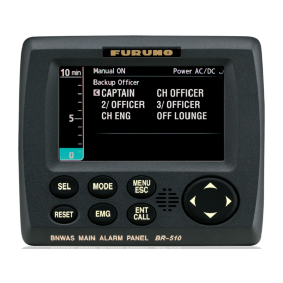
Page 12: Bnwas Display
The system status indicator rotates when the system is normal, and appears on all dis- plays. If the indicator is not rotating, there can be a problem with the system. Contact a FURUNO agent or dealer for information. Backup officer indication/selection You select the backup officer with the SEL key. -
Page 13: How To Adjust The Lcd Brilliance, Key Backlighting
1. MAIN ALARM PANEL Watch time interval countdown timer The length of the bar decreases as time progresses and the color of the bar changes with each stage. Dormant Period Prewarning 1st stage Watch time Watch time Watch time setting (min) setting (min) setting (min) Time remaining... -
Page 14: How To Select The Backup Officer
Mode The BR-500 has three main modes of operation: Manual OFF: The BNWAS is inactive. Use this mode when entering or just leaving harbor. No reset is necessary. Default setting. Manual ON: The BNWAS is active. Use this mode when the vessel is travelling on the open sea. -
Page 15: Watch Alarm Sequence
1. MAIN ALARM PANEL Watch Alarm Sequence The watch alarm checks for the presence of the OOW on the bridge. If equipment on the bridge (Main Alarm Panel, Timer Reset Panel, Backup Navigator, Autopilot, or Mo- tion Detector) is operated within the selected watch time interval, no alarm is given. If no equipment is operated within the selected watch time interval, the system contin- ues in the sequence shown below. - Page 16 1. MAIN ALARM PANEL 3. If the equipment connected to the system is not operated during the PREWARN- ING, the 1st stage begins: Power AC/DC WATCH ALARM(1st stage) Push any key. • Main Alarm Panel releases 15-second visual (in red) and audible alarms •...
- Page 17 1. MAIN ALARM PANEL Power AC/DC WATCH ALARM(3rd stage) Push [RESET] key to stop buzzer. • Main Alarm Panel continuously displays a visual alarm (in red) and sounds its buzzer until reset occurs • Timer Reset Panel continuously flashes its ALARM LED and sounds its buzzer until reset occurs •...
-
Page 18: Help Area
1. MAIN ALARM PANEL Equip- Dormant Pre- State ment color Period warning stage stage* stage Cabin DUTY LED Green Panel: ALARM LED public cabin Buzzer Flash Yellow Flashing Flashing Flashing* Flashing* Beacon *1 Captain selected as backup officer on Administrator menu. *2 Output if [2nd Stage] is set to ON in Administrator menu. -
Page 19: Operational Event Indications
1. MAIN ALARM PANEL 4) The message is erased when the reason for the alarm is removed. The table below shows the system failure messages. Indication Problem Color State Failure: Communication Communication failure Flashing between Processor Unit and Main Alarm Panel Failure: AC AC power failure Flashing... -
Page 20: How To Call A Navigation Officer
1. MAIN ALARM PANEL Manual ON Power AC/DC WATCH ALARM(2nd stage:Emergency Call) Push [RESET] key to stop buzzer. The system goes into the 2nd stage (or 3rd stage depending on system setting). In the 2nd stage, the following occurs: • Main Alarm Panel shows a 90-180-second visual alarm and sounds its buzzer 90- 180 seconds •... -
Page 21: Optional Equipment
OPTIONAL EQUIPMENT Timer Reset Panel BR-530, BR-550 The Timer Reset Panel BR-530 is installed on the bridge, and the WATERTIGHT Tim- er Reset Panel BR-550 is installed on the wing. A total of six can be installed. RESET ALARM (green) (yellow) RESET button... -
Page 22: Cabin Panel Br-540
2. OPTIONAL EQUIPMENT Cabin Panel BR-540 The Cabin Panel is installed in all navigation officers’ quarters and in public areas. The Cabin Panel releases audible and visual alarms if the OOW did not confirm presence on the bridge within the selected watch time interval. A total of 12 Cabin Panels can be installed. -
Page 23: Motion Detector Br-560
2. OPTIONAL EQUIPMENT Motion Detector BR-560 The Motion Detector BR-560 detects motion on the bridge. The maximum motion de- tection range is 5 m. The “motion” signal is output via the Processor Unit to tell the Main Alarm Panel to re- set the watch alarm. -
Page 24: Flash Beacon Br-570
2. OPTIONAL EQUIPMENT Flash Beacon BR-570 The Flash Beacon BR-570 flashes at the Prewarning phase and the 1st stage. It either flashes or is OFF at the 2nd and 3rd stages depending on the setting of segment #4 of DIP SW S1. See section 4.8. -
Page 25: Maintenance, Troubleshooting
MAINTENANCE, TROUBLESHOOTING This chapter provides maintenance and troubleshooting procedures for the user and serviceman. NOTICE WARNING o not apply paint, anti-corrosive ELECTRICAL SHOCK HAZARD Do not open the equipment. sealant or contact spray to plastic parts or equipment coating. This equipment uses high voltage that can cause Those items contain products that can electrical shock. -
Page 26: Fuse Replacement
3. MAINTENANCE, TROUBLESHOOTING Fuse Replacement The fuses on the PWR Board (24P0105) inside the Processor Unit protect the system from overvoltage and overcurrent. If the power is not on, have a technician check for blown fuse(s). If a fuse(s) has blown, replace the fuse(s) with one of the same rating. If the fuse(s) blows again, contact your dealer. -
Page 27: How To Check Connection Between Processor Unit/Cabin Panel/Timer Reset Panel
3. MAINTENANCE, TROUBLESHOOTING How to Check Connection Between Processor Unit/Cabin Panel/ Timer Reset Panel You can check the connection between the Processor Unit/Cabin Panel/Timer Reset Panel. The tested panel sends a test signal to the Processor Unit. The Processor Unit receives the test signal then commands that panel to light or flash its LEDs and sound its buzzer. -
Page 28: Life Expectancy Of Major Parts
3. MAINTENANCE, TROUBLESHOOTING Note 1: The watch timer is not reset during the test. Note 2: A Cabin Panel that is currently forwarding an alarm cannot be tested. Howev- er, you can test the Cabin Panels that are not forwarding an alarm. (For example, in the 2nd stage, a Cabin Panel other than the one in the back-up officer’s quarters can be tested.) Life Expectancy of Major Parts... -
Page 29: Installation
INSTALLATION Equipment Lists Standard supply Name Type Code No. Remarks Main Alarm Panel BR-510 Processor Unit BR-520 Installation Materials CP24-01701 001-117-860 For BR-510 CP24-01800 000-018-042 For BR-520, w/10 m cable CP24-01801 001-117-970 For BR-520, no cable Spare Parts SP24-00501 001-117-990 For BR-520, for V spec.* * Merchant vessel Optional supply... -
Page 30: Mounting Considerations
4. INSTALLATION Mounting Considerations Do the installation following the information in IEC 62616 Annex A and IMO MSC.128(75). • Locate the units away from exhaust pipes and vents. • Make sure the location has good ventilation. • Mount the units where shock and vibration are minimal. •... -
Page 31: Main Alarm Panel Br-510
4. INSTALLATION Main Alarm Panel BR-510 The Main Alarm Panel can be mounted on a desktop or flush mounted in a console, on the bridge. Follow the mounting considerations in section 4.2 Mounting Consider- ations to select a location. Additionally, the unit must be located on the bridge where a proper look out is provided. -
Page 32: Flush Mount
4. INSTALLATION 4.3.3 Shield film (option) If the screen is too bright with minimum bril- liance at nighttime, install the shield film to reduce the brilliance. 1. Clean the LCD with an LCD cleaning SHIELD FILM cloth. 2. Peel off the protective backing from the shield film. -
Page 33: Bulkhead Mount (Option)
4. INSTALLATION 4.5.2 Bulkhead mount (option) This mounting method requires the optional bulkhead mount kit (Type: OP24-20, Code No. 001-118-740-00), the contents of which are shown in the table below. The cable can be led into the unit from the bottom or rear of the unit. Name Type Code No. - Page 34 4. INSTALLATION 4. Fasten the cable to the Clamp with a cable tie (local supply). As shown in the fig- ure below, make the distance between the terminal and the cable tie 100 mm. 5. Fasten the Mount Base to the mounting location with four self-tapping screws (supplied).
- Page 35 4. INSTALLATION 2. Fasten the Mount Base/Clamp to the mounting location with four self-tapping screws (supplied). 3. Pass the signal cable through the Mount Case. 4. Connect the signal cable to the WAGO terminal block. See the interconnection di- agram. 5.
-
Page 36: Watertight Timer Reset Panel Br-550 (Option)
4. INSTALLATION 6. Fasten the Chassis to the Mount Case with binding screws (supplied) 7. Fasten the signal cable to the Clamp with a cable tie. Cable Tie Watertight Timer Reset Panel BR-550 (option) Follow the mounting considerations in section 4.2 Mounting Considerations when se- lecting a location. - Page 37 4. INSTALLATION 2. Connect the signal cable to the WAGO terminal block on the Chassis. See the in- terconnection diagram. 3. A gasket is fitted on the Chassis. Confirm that the gasket is correctly seated. If not correctly seated, re-seat the gasket, referring to the illustration below for the in- serting direction.
-
Page 38: Wiring
4. INSTALLATION Wiring 4.7.1 Processor Unit All cables are terminated at the Processor Unit. Remove the shield cover from the MAIN Board (24P0104). Connect the cables to their respective locations on those boards. Use the terminal opener (supplied) to open the terminals of the WAGO termi- nal blocks on the MAIN Board. -
Page 39: Wiring Information
4. INSTALLATION How to fabricate and fix cables to the Processor Unit 80 mm 80 mm Fix cables to post with cable tie Wrap wires with Wrap armor with vinyl tape. vinyl tape. How to fabricate cables for processor unit How to attach EMI core to power cable Attach supplied EMI core to the power cable. -
Page 40: Main Alarm Panel
4. INSTALLATION Item Description 40 m and the total length for all units is max. 150 m. For example, when Cable MPYC-7 (between BR-530/550 four BR-530 are installed: and BR-520) No.1 BR-530: 40 m No. 2 BR-530: 40 m No. 3 BR-530: 40 m No. -
Page 41: Timer Reset Panel, Cabin Panel, Motion Detector, Flash Beacon
4. INSTALLATION 4.7.4 Timer Reset Panel, Cabin Panel, Motion Detector, Flash Beacon The wiring procedure is common to all the above-mentioned units. Cable to use Description Cable MPYC-7 Timer Reset Panel (between respective Max. length of single cable: 40 m unit and BR-520) Max. -
Page 42: How To Fabricate Cables At External Equipment Side
4. INSTALLATION 4.7.5 How to fabricate cables at external equipment side Power cables for Processsor Unit (DPYC-1.5 (AC power), DPYC-2.5 (DC power)) L=Distance from cable clamp to terminal connection DPYC-1.5: φ = 11.7 mm Sheath Armor DPYC-2.5: φ = 12.8 mm Armor Sheath Cut the sheath. -
Page 43: Dip Switch, Rotary Switch Settings
4. INSTALLATION DIP Switch, Rotary Switch Settings A DIP switch and a Rotary switch are provided in the Processor Unit to adjust the equipment according to applicable regulations and ship’s requirements. Location of switches in the Processor Unit Rotary SW S2 SW position Frequency 4.2 kHz... -
Page 44: How To Adjust Led, Lamp Brilliance
The Administrator Menu has initial settings that set the system according to the requirements of your vessel. Only the Administrator of the system can enter the initial settings. 1. Press the MENU/ESC key. 2. You are asked to enter the password. See the FURUNO service technician for the password. Power AC/DC Intermittent2... - Page 45 4. INSTALLATION 3. Use the up or down arrow on the CursorPad to select a menu item then press the ENT/CALL key. An options window or spinner box appears depending on your selection. Intermittent1 Options window Spinner box (Buzzer Type) Intermittent2 (Watch Time Interval) 4.
- Page 46 4. INSTALLATION Menu Item Description Options Backup Change the name of navigation officers; add navigation Officer officers; set the function of the Cabin Panel in the quar- ters of the Captain. How to select the function of the Cabin Panel in the quarters of the Captain: 1) Select [1 CAPTAIN].
- Page 47 4. INSTALLATION Self TEST The self test checks the equipment for proper operation. 1. Use the CursorPad to select [Self TEST] from the Administrator menu then press the ENT/CALL key. Voltage (DC) Power AC/DC 11.9V BR-510/BR-520 No. of times Boot : 2450054-XX.XX CPU: 2450056-XX.XX ROM/RAM check, ROM, RAM...
-
Page 48: Service Menu
Only the Administrator of the sys- tem can open the Service menu. 1. Press the MENU/ESC key. 2. You are asked to enter the password. See the FURUNO service technician for the password. Note: If the BNWAS is active, the message shown right appears. - Page 49 4. INSTALLATION How to restore factory settings 1. Open the Service menu. 2. Use the CursorPad to select [Restore Factory Settings] then press the ENT/CALL key. 3. Use the CursorPad to select [ON] then press the ENT/CALL key. 4. Use the CursorPad to select "Yes" then press the ENT/CALL key. 5.
-
Page 50: I/O Sentence Information
4. INSTALLATION 4.11 I/O Sentence Information The BR-500 has no input sentences. Sentence Sentence construction $BNALR, hhmmss.ss,xxx,A,A,c- -c,*hh<CR><LF> - hhmmss.ss: This part may be left blank because BNWAS does not include UTC time information. - xxx: Designation of source of alarm or source of reset command. -
Page 51: Appendix 1 Menu Tree, Abbreviations, Jis Cable Guide
APPENDIX 1 MENU TREE, ABBREVIATIONS, JIS CABLE GUIDE Menu Tree (default settings in bold italic) Administrator menu Watch Time Interval (3-12 min, 10 min) MENU 2nd Stage Interval (90-180 s, 90 s) Captain Backup (OFF, ON) (Requires 2nd Stage (OFF, ON) password.) 1 Captain (Backup, Captain) Backup Officer... - Page 52 EX: DPYCYS - 1.5 MPYC - 5 TTYCS-4 Designation type Designation type # of cores Core Area (mm The following reference table lists gives the measurements of JIS cables commonly used with Furuno products: Core Cable Core Cable Diameter Diameter...
-
Page 53: Specifications
FURUNO BR-500 SPECIFICATIONS OF BRIDGE NAVIGATIONAL WATCH ALARM SYSTEM BR-500 MAIN ALARM PANEL (BR-510) Display 4.3-inch color LCD, 480 x 272 dots Brilliance 0.15 to 500 cd/m (w/o shield film) Status indication Dormant period, Alarm stage, Backup officer, Power status,... - Page 54 FURUNO BR-500 Resolution 0.8 m/s (minimum speed) Signal output Contact closure (normal open) FLASH BEACON (BR-570, OPTION) Previous visible alarm Watch alarm lamp (yellow) Dimmer External or inner volume POWER SOURCE 100-230 VAC: 0.6-0.4 A, 1 phase, 50/60 Hz 24 VDC: 1.0 A (back-up source)
- Page 63 Y.NISHIYAMA 9/Feb/2011...
- Page 70 D-10...
- Page 71 D-11...
- Page 72 D-12...
- Page 73 D-13...
- Page 74 D-14...
- Page 75 D-15...
- Page 77 CABIN PANEL: UP TO 12 SETS FOR OFFICER AND PUBLIC USE. TOTAL CABLE LENGTH: UP TO 300m IV-2sq. キャビンパネル CABIN PANEL BR-540 DUTY-LEDおよびTEST機能は使用不可 DUTY-LED AND TEST FUNCTIONS ARE DISABLE DRAWN TITLE 注記 NOTE BR-500 T.YAMASAKI 11/Mar/2011 *1)造船所手配。 *1: SHIPYARD SUPPLY. CHECKED 名称 船橋航海当直警報装置 H.MAKI *2)オプション。 *2: OPTION. 11/Mar/2011 APPROVED *3)キャビンパネルは最大3台まで接続可能。...
-
Page 78: Index
INDEX Numerics 2nd stage interval........4-17 RESET key..........1-1 Abbreviations ..........AP-1 SEL key..........1-1 Alarm sequence ........1-5 Software history ........... vi System failure ........... 1-8 Backlighting..........1-3 Backup officer ......... 4-18 Timer reset panel ........2-1 Backup officer selection ......1-4 Troubleshooting ........
Need help?
Do you have a question about the BR-500 and is the answer not in the manual?
Questions and answers