Table of Contents
Advertisement
Advertisement
Table of Contents

Related Manuals for Furuno IC-350


Summary of Contents for Furuno IC-350
- Page 1 OPERATOR'S MANUAL ALARM UNIT IC-350 Model www.furuno.com...
- Page 3 How to discard a used battery Some FURUNO products have a battery(ies). To see if your product has a battery, see the chapter on Maintenance. Follow the instructions below if a battery is used. Tape the + and - terminals of bat- tery before disposal to prevent fire, heat generation caused by short circuit.
- Page 4 Continued use of the equipment can cause Fire or electrical shock can result. fire or electrical shock. Consult a FURUNO agent or dealer for advice. Do not operate the equipment with wet hands.
- Page 5 SAFETY INSTRUCTIONS Precautions for the installer WARNING CAUTION Be sure the voltage at the ship's switch- Shut off the power at the switchboard board is compatible with the voltage before beginning the installation. rating of this equipment. Fire or electrical shock can result if the The rated voltage of this equipment is equipment is powered while it is being 24 VDC.
-
Page 6: Table Of Contents
TABLE OF CONTENTS FOREWORD ........................v SYSTEM CONFIGURATION ..................vi INSTALLATION ...................... 1 1.1 Equipment Lists......................1 1.2 How to Install the Alarm Unit..................1 1.3 Connections ........................ 2 1.3.1 Where to connect the cables ................2 1.3.2 Cable fabrications ....................3 1.4 Settings ........................ -
Page 7: Foreword
FOREWORD Congratulations on your choice of the FURUNO IC-350 Alarm Unit. We are confident you will see why the FURUNO name has become synonymous with quality and reliability. Since 1948, FURUNO Electric Company has enjoyed an enviable reputation for quality marine electronics equipment. -
Page 8: System Configuration
SYSTEM CONFIGURATION Standard configuration shown with solid lines. Radiotelephone External No.1 VHF Alarm Radiotelephone ALARM UNIT No. 2 VHF Alarm Unit IC-350 Radiotelephone IC-350 (No.1) (No.2) No. 1 Inmarsat-C MES No. 2 Incoming Inmarsat-C MES Indicator IC-303 NAVTEX Can be connected only... -
Page 9: Installation
INSTALLATION Equipment Lists Standard supply Name Type Code No. Remarks Alarm Unit IC-350 — Installation Materials CP05-11701 000-041-190 1 set Self-tapping screws (φ4×20, 4pcs) (000-158-850-10) Accessory FP05-06401 001-058-090 SPARE sticker Optional supply Name Type Remarks Rectifier PR-62 AC input, 24 VDC output... -
Page 10: Connections
TB #3 - 4 *1: Power must be supplied from a power source which is backed-up by radio battery. *2: IC-350 dual installation requires setting modification. *3: The IC-303 can be connected only when the SSB radiotelephone FS-1570/2570/5070 is connected. -
Page 11: Cable Fabrications
1. INSTALLATION 1.3.2 Cable fabrications This section shows the cable fabrications. The text between parentheses in the section titles are the names of Japan Industry Standard (JIS) cables. Use those cables or their equivalents. Power cable (DPYC-1.5) 8 to 9 8 to 9 Armor Sheath... - Page 12 1. INSTALLATION Cable for external alarm (DPYC-1.5) 8 to 9 8 to 9 Armor Sheath Core 30 30 Attach WAGO Vinyl tape connector Set this section in cable clamp How to fasten a WAGO connector Push Terminal opener (located inside the equipment) 1.
- Page 13 Not used Power Cable To External Alarm To SSB Radiotelephone To NAVTEX Receiver To No.2 Alarm unit (IC-350) To No. 2 Inmarsat C MES To No. 1 VHF Radiotelephone To No. 1 Inmarsat C MES To No. 2 VHF Radiotelephone...
-
Page 14: Settings
1. INSTALLATION Settings How to set the external equipment Set the DIP switch S101 on the PANEL Board (05P0820) according to equipment connected. All switches are in the OFF position in the factory setting. Set a switch in the ON position if the related equipment is not connected. - Page 15 1. INSTALLATION Short plug position and SSB radiotelephone FS-1570/2570/5070: Change the position of the short plug of pin headers J101, J203, J204, J205, J301, J302 as shown in the figure below.FS-1575/2575/5075: No adjustment is necessary; use the default positions. (All short plugs are between #2 & 3.) MAIN board 05P0819 J205...
- Page 16 • Set the dip switch #1 on S102 to ‘ON’ for No.1 IC-350. (#2 to #4: OFF) • Set the dip switch #1 and #2 on S102 to ‘ON’ for No.2 IC-350. (#3 and #4: OFF) Refer to the figure on page 4 for the location of S102.
-
Page 17: Operation
How to Set the Unit to Stand-by 1. Supply power from a power source which is backed-up by radio battery to turn on the IC-350. All buttons in the IC-350 illuminate. Run the IC-350 while underway. A DISTRESS button does not illuminate if the equipment name shown above the button is not connected. -
Page 18: When You Receive A Distress Signal
If YOUR ship is in distress, send a distress signal and do distress communications with a coast station by radiocommunications. The IC-350 has five distress buttons. Use the No.1 VHF button (leftmost DISTRESS button) to send a distress signal in normal use. -
Page 19: How To Operate The Dual Alarm Unit
2. OPERATION How to Operate the Dual Alarm Unit You can operate No.2 alarm unit from remote location by dual alarm unit installation. When the No.2 alarm unit is installed, do the operation as follows. Purpose Operation Turn the power on Both equipment can turn on first. -
Page 20: Maintenance
MAINTENANCE NOTICE Do not apply paint, anti-corrosive sealant or contact spray to coating or plastic parts of the equipment. Those items contain organic solvents that can damage coating and plastic parts, especially plastic connectors. Maintenance Check the points shown below once a month to help keep the equipment in good condition. Item Check point Cables... -
Page 21: Circuit Breaker
3. MAINTENANCE Circuit Breaker The circuit breaker inside the IC-350 activates for equipment problems or high voltage. The button on the breaker comes out when the breaker activates. Push the button to reset the breaker. If you cannot turn ON the power (from the ship’s switchboard), contact a FURUNO agent or dealer for instruction. -
Page 22: Specifications
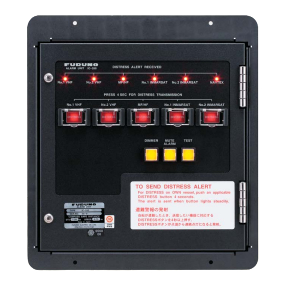
SPECIFICATIONS OF ALARM UNIT IC-350 IC-350 is a GMDSS Distress Alarm Panel that is normally installed at conning position. Pressing the button on the panel transmits the distress alert. When the incoming distress or urgency call is received, the panel generates audible and visible alarms. The buttons on panel are clearly and visibly identified. - Page 23 30/Sep/08 R.Esumi...
- Page 25 (title and/or number and date of issue of the standard(s) or other normative document(s)) For assessment, see • EMC Test Report FLI 12-08-024 Rev. A, June 11, 2008 prepared by Furuno Labotech International Co., Ltd. This declaration is issued according to the Directive 2014/30/EU of the European Parliament and of the Council of 26 February 2014 on the harmonisation of the laws of the Member States relating to electromagnetic compatibility.
- Page 28 ・FURUNO Authorized Distributor/Dealer 9-52 Ashihara-cho, Nishinomiya, 662-8580, JAPAN A : JUN 2008 Printed in Japan All rights reserved. D1 : AUG . 07, 2018 Pub. No. OME-56650-D1 ( ETMI ) IC-350 0 0 0 1 6 9 2 0 4 1 3...
Need help?
Do you have a question about the IC-350 and is the answer not in the manual?
Questions and answers