Table of Contents
Advertisement
Quick Links
Advertisement
Table of Contents

Related Manuals for AXIOMTEK MANO300 Series


Summary of Contents for AXIOMTEK MANO300 Series
- Page 1 MANO300 Series ® Intel Braswell SoC CPU Mini ITX Motherboard User’s Manual...
- Page 2 Axiomtek does not make any commitment to update the information in this manual. Axiomtek reserves the right to change or revise this document and/or product at any time without notice. No part of this document may be reproduced, stored in a retrieval system, or transmitted, in any form or by any means, electronic, mechanical, photocopying, recording, or otherwise, without the prior written permission of Axiomtek Co., Ltd.
-
Page 3: Esd Precautions
It discharges static electricity from your body. Wear a wrist-grounding strap, available from most electronic component stores, when handling boards and components. Trademarks Acknowledgments Axiomtek is a trademark of Axiomtek Co., Ltd. ® ® Intel and Celeron are trademarks of Intel Corporation. -
Page 4: Table Of Contents
Table of Contents Disclaimers ...................... ii ESD Precautions ..................... iii Chapter 1 Introduction ..........1 Features ....................1 Specifications ..................2 Utilities Supported ................. 3 Block Diagram ..................4 Chapter 2 Board and Pin Assignments ....5 Board Layout ..................5 Rear I/O .................... - Page 5 2.4.19 PCI-Express x1 Slot (CN27) ..............19 2.4.20 PCI-Express Mini Card Connector (CN28) ..........20 2.4.21 mSATA Slot (CN29) ................... 21 2.4.22 VGA Connector (CN30) ................21 2.4.23 HDMI Connector (CN31) ................22 2.4.24 Audio Jack (CN32) ..................22 2.4.25 Front Audio Header (CN33) ..............
- Page 6 This page is intentionally left blank.
-
Page 7: Chapter 1 Introduction
MANO300 Mini ITX Motherboard Chapter 1 Introduction ® ® The MANO300 is a Mini ITX board based on Intel Celeron N3160 processor. It delivers outstanding system performance through high-bandwidth interfaces, multiple I/O functions for interactive applications and various embedded computing solutions. There are two 204-pin DDR3L SO-DIMM for DDR3L 1600/1333MHz memory with maximum capacity up to 8GB. -
Page 8: Specifications
MANO300 Mini ITX Motherboard Specifications ® ® Intel Celeron quad core N3160 (up to 2.08GHz). BIOS AMI BIOS. System Memory Two 204-pin SO-DIMM sockets. The upper socket must be installed. Maximum up to 8GB DDR3L memory. ... -
Page 9: Utilities Supported
MANO300 Mini ITX Motherboard Power Input One ATX power input connector. One 12V only ATX power input connector. One 12VDC jack power input connector. Please plug only one of the three power input interfaces when power on. Note ... -
Page 10: Block Diagram
MANO300 Mini ITX Motherboard Block Diagram Introduction... -
Page 11: Board And Pin Assignments
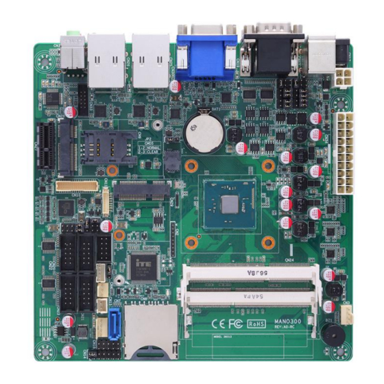
MANO300 Mini ITX Motherboard Chapter 2 Board and Pin Assignments Board Layout Board and Pin Assignments... -
Page 12: Rear I/O
MANO300 Mini ITX Motherboard Rear I/O Front Audio Header (CN33) SATA 3.0 Connector (CN7) LVDS Signal Header (CN10) SD Card Slot (CN8) LVDS Backlight Control Header (CN11) DDR3L SO-DIMM Sockets (CN24) LVDS VDD Select Jumper (JP4) ATX Power Input Connector (CN34) LVDS Backlight PWM/CCFL Select ATX 12V Only Power Input Connector (CN13) Jumper (JP5) -
Page 13: Jumper Settings
And remove jumper clip from 2 jumper pins to open. The following illustration shows how to set up jumper. Before applying power to MANO300 Series, please make sure all of the jumpers are in factory default position. Below you can find a summary table of all jumpers and onboard default settings. -
Page 14: Clear Cmos Select (Jp2)
MANO300 Mini ITX Motherboard Jumper Description Setting Clear CMOS 1-2 Close Default: Normal AT/ATX Power Mode Select 1-2 Close Default: ATX Mode LVDS Backlight PWM/CCFL Select 1-2 Close Default: PWM LVDS VDD Select 1-2 Close Default: +3.3V 1-2 Close COM1 RS-232/422/485 Mode Select 3-5, 4-6 Close Default: RS-232 3-5, 4-6 Close... -
Page 15: Lvds Backlight Pwm/Ccfl Select (Jp5)
MANO300 Mini ITX Motherboard 2.3.3 LVDS Backlight PWM/CCFL Select (JP5) This 3x1-pin p=2.54mm jumper enables you to select PWM or voltage control mode for LVDS backlight control header (CN11). These two control modes are for adjusting the brightness of LVDS panel. Function Setting Controlled by PWM (Default) -
Page 16: Com2 Rs-232/422/485 Mode Select (Jp10, Jp11, Jp12)
MANO300 Mini ITX Motherboard 2.3.6 COM2 RS-232/422/485 Mode Select (JP10, JP11, JP12) Use these jumpers (3x2-pin p=2.54mm) to set COM2 port to operate as RS-232, RS-422 or RS-485 communication mode. Function Setting JP10 JP11 JP12 JP10 1-2 close RS-232 mode JP11 3-5, 4-6 close (Default) JP12 3-5, 4-6 close... -
Page 17: Connectors
MANO300 Mini ITX Motherboard Connectors Signals go to other parts of the system through connectors. Loose or improper connection might cause problems, please make sure all connectors are properly and firmly connected. Here is a summary table showing connectors on the hardware. Connector Description CPU Fan Connector... -
Page 18: Fan Connectors (Cn3 And Cn4)
MANO300 Mini ITX Motherboard 2.4.1 Fan Connectors (CN3 and CN4) This motherboard has two fan connectors. You can find fan speed option(s) at BIOS Setup Utility. For further information, see BIOS Setup Utility: Advanced\HW Monitor\PC Health Status. The CN3 (4x1-pin p=2.54mm) is for CPU fan interface. Signal +12V FAN Speed Detection... -
Page 19: Sata 3.0 Connector (Cn7)
MANO300 Mini ITX Motherboard 2.4.4 SATA 3.0 Connector (CN7) This Serial Advanced Technology Attachment (Serial ATA or SATA) connector is for SATA 3.0 interface allowing up to 6.0Gb/s data transfer rate. It is a computer bus interface for connecting to devices such as hard disk drive. Signal SATA_TX+ SATA_TX-... -
Page 20: Lvds Signal Header (Cn10)
MANO300 Mini ITX Motherboard 2.4.7 LVDS Signal Header (CN10) This motherboard has a 20x2-pin p=1.00mm header for LVDS panel interface. Signal Signal [**] GND(Detect) LVDS_B_DATA3- LVDS_B_DATA0- LVDS_B_DATA3+ LVDS_B_DATA0+ LVDS_B_CLK- LVDS_B_DATA1- LVDS_B_ CLK + LVDS_B_DATA1+ LVDS_A_DATA0- LVDS_B_DATA2- LVDS_A_DATA0+ LVDS_B_DATA2+ LVDS_A_DATA1- LVDS_A_DATA3- LVDS_A_DATA1+ LVDS_A_DATA3+ LVDS_PRSNT#... -
Page 21: 12Vdc Jack Power Input Connector (Cn12)
MANO300 Mini ITX Motherboard 2.4.9 12VDC Jack Power Input Connector (CN12) Firmly insert power adapter into this connector. Loose connection may cause system instability and make sure all components/devices are properly installed before connecting. 2.4.10 ATX 12V Only Power Input Connector (CN13) This is a 4-pin connector for DC +12V power input. -
Page 22: Power Status Header (Cn15)
MANO300 Mini ITX Motherboard 2.4.12 Power Status Header (CN15) This is power button header (2x1-pin p=2.54mm), let customer know the power status of this board. Signal PWR+ PWR- 2.4.13 DC12V/5V Power Output Connector (CN16) This is a 4x1-pin p=2.54mm connector for DC +12V and +5V power output. Signal +12V 2.4.14... -
Page 23: Gpio Header (Cn18)
MANO300 Mini ITX Motherboard 2.4.15 GPIO Header (CN18) This header (5x2-pin p=2.54mm) is for digital I/O interface. Signal Signal SIO_GPO74 SIO_GPI70 (0xA06, Bit4, H) (0xA06, Bit0) SIO_GPO75 SIO_GPI71 (0xA06, Bit5, H) (0xA06, Bit1) SIO_GPO76 SIO_GPI72 (0xA06, Bit6, H) (0xA06, Bit2) SIO_GPO77 SIO_GPI73 (0xA06, Bit7, H) -
Page 24: Com Headers (Cn20~Cn23)
MANO300 Mini ITX Motherboard 2.4.17 COM Headers (CN20~CN23) The motherboard comes with 5x2-pin p=2.54mm headers for COM3~COM6 serial port interfaces. Only COM3 comes with power capability on DCD# and RI# pins by setting JP13 (see section 2.3.7). Signal Signal DCD# DSR# CN22 CN20 (COM3) -
Page 25: Pci-Express X1 Slot (Cn27)
MANO300 Mini ITX Motherboard 2.4.19 PCI-Express x1 Slot (CN27) This motherboard has one PCI-Express x1 slot. Signal Signal +12V PRSNT1# +12V +12V RSVD +12V SMCLK SMDAT +3.3V +3.3V 3.3Vaux +3.3V WAKE# PERST# REFCLK+ HSOP0 REFCLK- HSON0 HSIP0 HSIN0 Board and Pin Assignments... -
Page 26: Pci-Express Mini Card Connector (Cn28)
MANO300 Mini ITX Motherboard 2.4.20 PCI-Express Mini Card Connector (CN28) This is a PCI-Express Mini Card connector applying to PCI-Express or USB 2.0. It also complies with PCI-Express Mini Card Spec. V1.2. Signal Signal WAKE# +3.3VAUX RSVD1 RSVD2 +1.5V CLKREQ# UIM_PWR UIM_DAT REFCLK-... -
Page 27: Msata Slot (Cn29)
MANO300 Mini ITX Motherboard 2.4.21 mSATA Slot (CN29) Signal Signal WAKE# +3.3VAUX RSVD1 RSVD2 +1.5V CLKREQ# UIM_PWR UIM_DAT REFCLK- UIM_CLK REFCLK+ UIM_REST UIM_VPP RSVD3 RSVD4 W_DISABLE# PERST# PERN0 +3.3VAUX PERP0 +1.5V SMB_CLK PETN0 SMB_DATA PETP0 USB_D- USB_D+ +3.3VAUX +3.3VAUX RVD5 RVD6 +1.5V RVD7... -
Page 28: Hdmi Connector (Cn31)
MANO300 Mini ITX Motherboard 2.4.23 HDMI Connector (CN31) The HDMI (High-Definition Multimedia Interface) is a compact digital interface which is capable of transmitting high-definition video and high-resolution audio over a single cable. Signal Signal HDMI OUT_DATA2+ HDMI OUT_DATA2- HDMI OUT_DATA1+ HDMI OUT_DATA1- HDMI OUT_DATA0+ HDMI OUT_DATA0-... -
Page 29: Atx Power Input Connector (Cn34)
MANO300 Mini ITX Motherboard 2.4.26 ATX Power Input Connector (CN34) Steady and sufficient power can be supplied to all components on the board by connecting power connector. Please make sure all components and devices are properly installed before connecting the power connector. External power supply plug fits into this connector in only one orientation. - Page 30 MANO300 Mini ITX Motherboard This page is intentionally left blank. Board and Pin Assignments...
-
Page 31: Chapter 3 Hardware Description
Make sure all correct settings are arranged for your installed microprocessor to prevent the CPU from damages. BIOS The MANO300 Series uses AMI Plug and Play BIOS with a single SPI Flash. System Memory The MANO300 supports two 204-pin DDR3L SO-DIMM sockets for maximum memory capacity up to 8GB DDR3L SDRAMs. - Page 32 MANO300 Mini ITX Motherboard This page is intentionally left blank. Hardware Description...
-
Page 33: Ami Bios Setup Utility
MANO300 Mini ITX Motherboard Chapter 4 AMI BIOS Setup Utility The AMI UEFI BIOS provides users with a built-in setup program to modify basic system configuration. All configured parameters are stored in a flash chip to save the setup information whenever the power is turned off. - Page 34 MANO300 Mini ITX Motherboard Hot Keys Description Left/Right The Left and Right <Arrow> keys allow you to select a setup screen. The Up and Down <Arrow> keys allow you to select a setup screen or sub Up/Down screen. The <Enter>...
-
Page 35: Main Menu
MANO300 Mini ITX Motherboard Main Menu When you first enter the setup utility, you will enter the Main setup screen. You can always return to the Main setup screen by selecting the Main tab. System Time/Date can be set up as described below. -
Page 36: Advanced Menu
MANO300 Mini ITX Motherboard Advanced Menu The Advanced menu also allows users to set configuration of the CPU and other system devices. You can select any of the items in the left frame of the screen to go to the sub menus: ►... - Page 37 MANO300 Mini ITX Motherboard Super IO Configuration You can use this screen to select options for the Super IO Configuration, and change the value of the selected option. A description of the selected item appears on the right side of the screen.
- Page 38 MANO300 Mini ITX Motherboard Hardware Monitor This screen monitors hardware health status. This screen displays the temperature of system and CPU, cooling fans speed in RPM and system voltages (VCC_CPU, VCC_DDR, +12V, +5V, +3.3V and VBAT). AMI BIOS Setup Utility...
- Page 39 MANO300 Mini ITX Motherboard Smart Fan Function This screen allows you to select CPU fan mode. CPU_Fan1 Mode This item allows you to select CPU fan mode, which can be set to Full on, Manual, Auto PWM or Auto RPM Mode. AMI BIOS Setup Utility...
- Page 40 MANO300 Mini ITX Motherboard S5 RTC Wake Settings Wake system from S5 Enable or disable system wake on alarm event. It allows you to wake up the system in a certain time. Select Fixed Time to set the system to wake on the specified time. Use <> <>...
- Page 41 MANO300 Mini ITX Motherboard Utility Configuration BIOS Flash Utility BIOS flash utility configuration. For more detailed information, please refer to Appendix A. AMI BIOS Setup Utility...
- Page 42 MANO300 Mini ITX Motherboard ACPI Settings You can use this screen to select options for the ACPI configuration, and change the value of the selected option. A description of the selected item appears on the right side of the screen.
- Page 43 MANO300 Mini ITX Motherboard CPU Configuration This screen shows the CPU information, and you can change the value of the selected option. AMI BIOS Setup Utility...
- Page 44 MANO300 Mini ITX Motherboard SATA Configuration During system boot up, the BIOS automatically detects the presence of SATA devices. In the SATA Configuration menu, you can see the currently installed hardware in the SATA ports. SATA Controller Enable or disable the SATA controller feature. Port 0~1 Enable or disable the onboard SATA port 0~1.
- Page 45 MANO300 Mini ITX Motherboard USB Configuration USB Devices Display all detected USB devices. Legacy USB Support Use this item to enable or disable legacy support for USB devices. The default setting is Enabled. Auto option disables legacy support if no USB devices are connected. Disable option will keep USB devices available only for EFI applications.
-
Page 46: Chipset Menu
MANO300 Mini ITX Motherboard Chipset Menu The Chipset menu allows users to change the advanced chipset settings. You can select any of the items in the left frame of the screen to go to the sub menus: ► North Bridge ►... - Page 47 MANO300 Mini ITX Motherboard North Bridge This screen allows users to configure parameters of North Bridge chipset. Primary IGFX Boot Display Select the video device which will be activated during POST (Power-On Self Test). The default is LVDS. LVDS Panel Type Select LVDS panel resolution.
- Page 48 MANO300 Mini ITX Motherboard South Bridge This screen allows users to configure parameters of South Bridge chipset. XHCI Mode Select operation mode of XHCI controller. Audio Controller Control detection of the audio device. - Disabled: Audio device will be unconditionally disabled. - Enabled: Audio device will be unconditionally enabled.
-
Page 49: Security Menu
MANO300 Mini ITX Motherboard Security Menu The Security menu allows users to change the security settings for the system. Administrator Password This item indicates whether an administrator password has been set (installed or uninstalled). User Password This item indicates whether a user password has been set (installed or uninstalled). AMI BIOS Setup Utility... -
Page 50: Boot Menu
MANO300 Mini ITX Motherboard Boot Menu The Boot menu allows users to change boot options of the system. Bootup NumLock State Use this item to select the power-on state for the keyboard NumLock. Quiet Boot Select to display either POST output messages or a splash screen during boot-up. ... -
Page 51: Save & Exit Menu
MANO300 Mini ITX Motherboard Save & Exit Menu The Save & Exit menu allows users to load your system configuration with optimal or fail-safe default values. Save Changes and Exit When you have completed the system configuration changes, select this option to leave Setup and return to Main Menu. - Page 52 MANO300 Mini ITX Motherboard Discard Changes Select this option to quit Setup without making any permanent changes to the system configuration. Select Discard Changes from the Save & Exit menu and press <Enter>. Select Yes to discard changes. Restore Defaults It automatically sets all Setup options to a complete set of default settings when you select this option.
-
Page 53: Appendix Abios Flash Utility
Please read and follow the instructions below carefully. In your USB flash drive, create a new folder and name it “Axiomtek”, see figure below. Copy BIOS ROM file (e.g. MANO300.005) to “Axiomtek” folder. - Page 54 Select the USB drive containing BIOS ROM file you want to update using the <> or <> key. Then press <Enter> to get into “Axiomtek” folder. Now you can see the BIOS ROM file on the screen, press <Enter> to select.
- Page 55 MANO300 Mini ITX Motherboard Please wait while BIOS completes the entire flash update process: erase data, write new data and verify data. 10. When you see the following figure, press <Enter> to finish the update process. After that the system will shut down and restart immediately. BIOS Flash Utility...
Need help?
Do you have a question about the MANO300 Series and is the answer not in the manual?
Questions and answers